
 ACES' preference for rapid, efficient prototyping (thereby leading to increased productivity) continues to inspire the development of an extraordinary inventoryof custom printed circuit boards (PCBs). These assets are intended for use as standalone components or either inserted perpendicular (Appliances) or parallel (Shields) into the Arduino UNO or the Dolgin Development Board (DDB) based on the ATtiny24/44/84.
 Although there are few experiences as satisfying as receiving your first PCB, it comes with a heavy cost. Not in dollars, but in time. Not every ACE is willing to make this substantial investment in their skill development, but those that do, ascend to the next level where their PCB Design Skills can be married to their 2D/3D Design Skills. This puts them miles ahead of their secondary peers and opens the doors of opportunity after graduation. So, to flatten out your EAGLE PCB learning curve, here are my recommendations for beginners.
Users wishing to add to our device inventory are encouraged to install one or both of our two custom EAGLE Parts Libraries: THT, SMT as many of the common components have been collected and adapted for the particular needs of ACES and the DES.
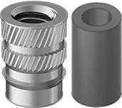
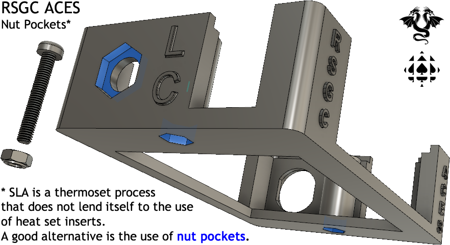
| The marriage of PCBs with 3D printed (thermoplastic) cases is facilitated through the use of heat-set insets as depicted in the image to the right. Our ACES program sources the M3×0.5 mm brass versions with an installed depth of 6.4 mm from McMaster-Carr. PCB designs should create mounting holes with a diameter of 3.2 mm to accommodate these insets. Click on the image to the right for a drawing. |
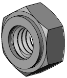
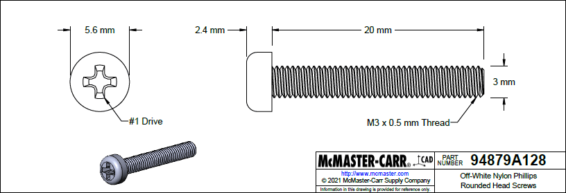
ACES preferred fasteners are M3 nylon and we usually stock screws, nuts, and hex standoffs of various lengths. 3D thermoset printing (as is done with resin by JLCPCB) does not lend itself to the use of heat-set insets. ACES' preferred PCB/Case mounting alternative is to use nut pockets. |
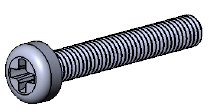
McMaster-Carr offers a wide variety of screws and fastenars of all sorts. Delivery is overnight. The DES maintains an inventory of M3 Nylon screws, with Phillips heads, in various lengths, between 5 mm and 20 mm. We typically have both off-white and black. |
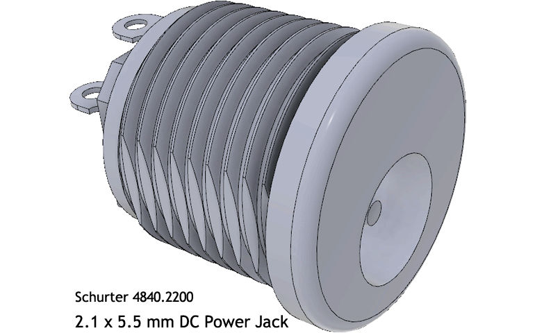
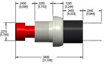
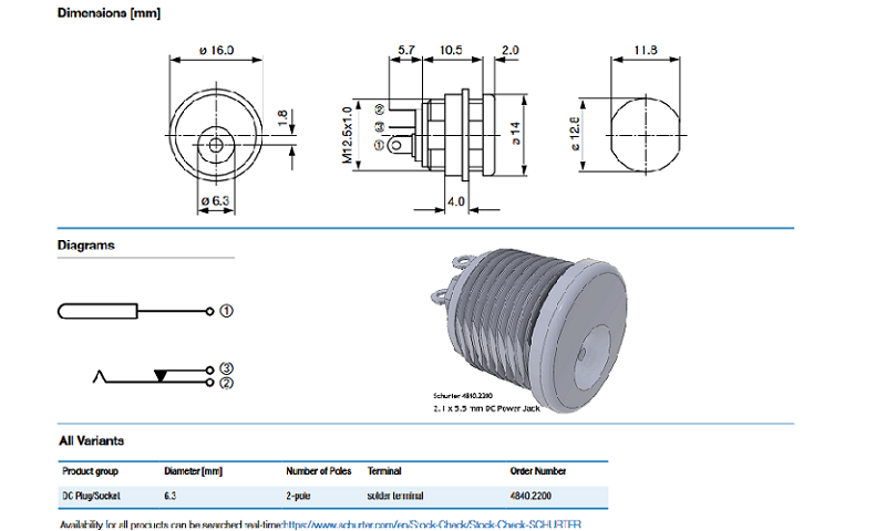
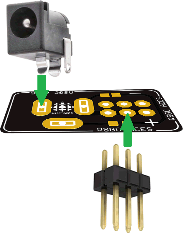
There are numerous options available for a female barrel jconnector. I prefer the panel mount, Schurter 4840_2200 device for side mounted access in our cases. The black, all-plastic housing is esthetically and electrically neutral.
Furthermore, unlike some of the inexpensive metal ones on Amazon, the fit is consistent, as are the polarity (+/-) of the solder lugs. |
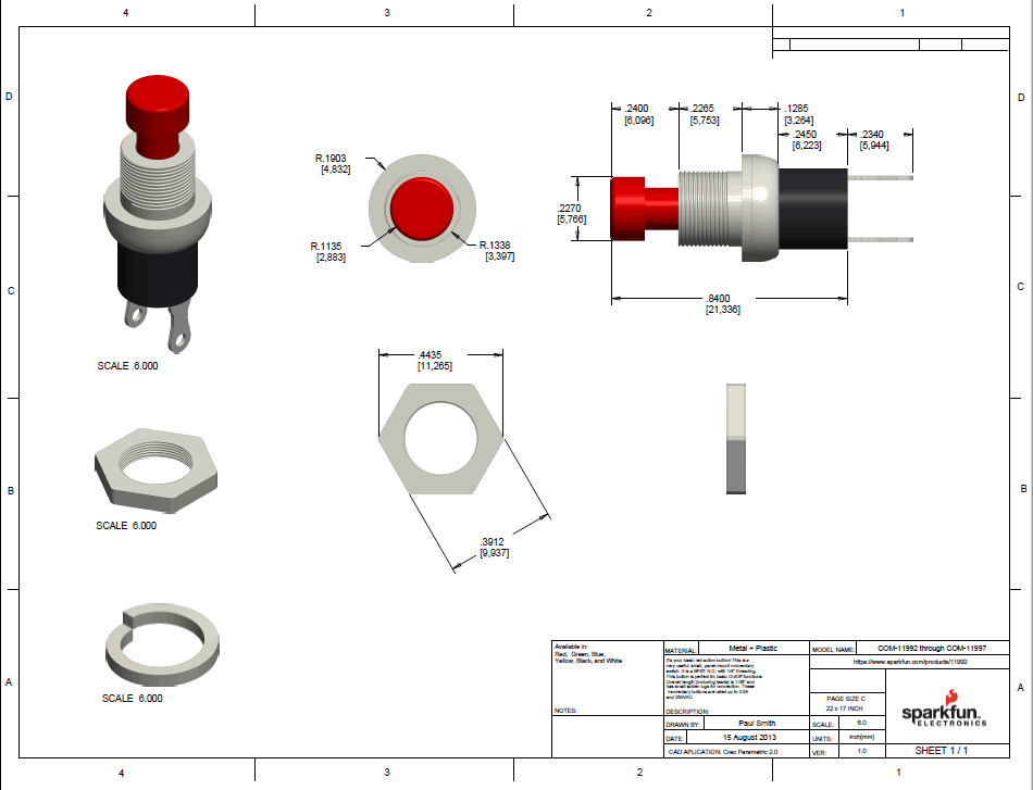
Panel mount devices such as momentary push buttons, toggle switches, and potentiometers come in a variety of dimensions. One such device is pictured below. This SPST NO Push Button is used as a reset switch in the ACES' Perma-Proto Kit. The key to its simple fastening within the resin-printed case is the nut pocket that permits simple thumb tightening. |
 |
 |
 |
 |
 |
Inventory
- (THT) Adder/Subtractor (June 2026)
- (SMT Breadboard Appliance) Double Dabble Display (March 2026)
- (THT) Minute Minder (March 2026)
- (THT/SMT Breadboard Appliance) Adder Stick (November 2025)
- (THT/SMT) 4-Way Traffic Light (October 2025)
- (SMT Breadboard Appliance) Pierce Oscillator (October 2025)
- (SMT) USB CharlieClock (September 2025)
- (THT/SMT) ICSP Adapter (September 2025)
- (SMT) USB CharlieClock (September 2025)
- (THT) Inductor Visualizer (August 2025)
- (THT Breadboard Appliance) nRF24L01 Nano-Compatible Breakout Board (March 2025)
- (THT) RPN Calculator Backplane (January 2025)
- (THT) Keypad Voltmeter (January 2025)
- (THT/SMT) One-Wire Keypads (January 2025)
- (Training Device) ATmega328p SMT Trainer (October 2024)
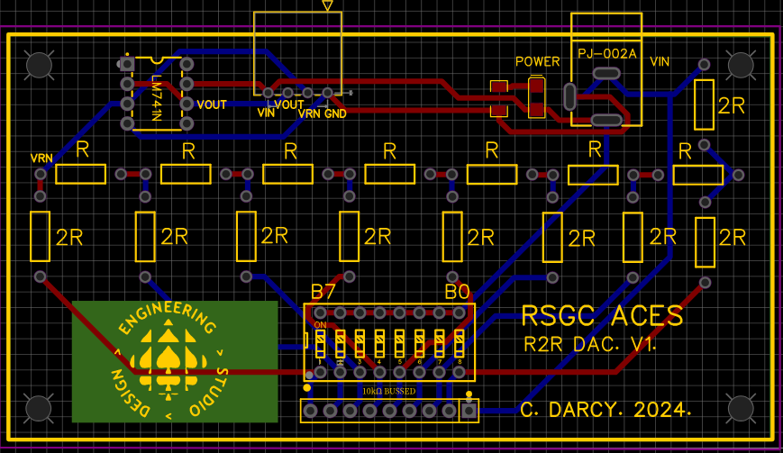
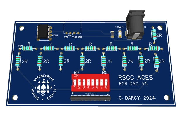
- (THT) R/2R DAC (September 2024)
- (THT Protoboard) ACES Full-Size Perma-Proto (June 2024)
- (Training Device/Breadboard Appliance) Davidge ATtiny414 Development Board (May 2024)
- (SMT) CharlieClock (April 2024)
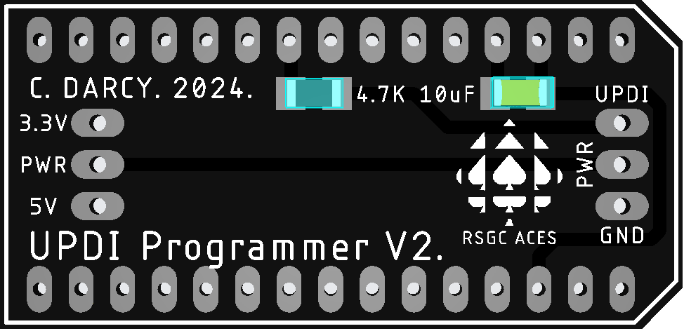
- (Programmer) UPDI (Unified Program and Debug interface) (March 2024)
- (THT Breadboard Appliance) CR1220 Coin Cell Retainer (January 2024)
- (SMT) ATtiny85 Clock (December 2023)
- (THT) ATtiny84 Clock(December 2023)
- (THT Breadboard Appliance) DIP Switch Bank (November 2023)
- (THT) Wien-Bridge Oscillator V1 (June 2023)
- (THT) ACES LED Tester (February 2023)
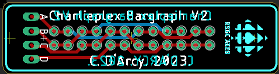
- (THT) ACES Morland Bargraph V4 (January 2023)
- (THT) ACES ATtiny85 ISP BoB (January 2023)
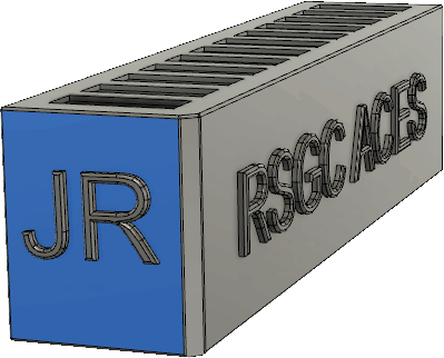
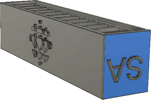
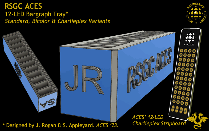
- (Design) ACES 12-LED Bargraph Holder (January 2023)
- (THT) Joule Thief (January 2023)
- (THT/SMT) ISP Breakout Board V3 (January 2023, JLCPCBs, 50 pcs)
- (THT/SMT) ACES Xmas Tree (January 2023, JLCPCBs, 5 pcs)
- (THT with enhanced SMT) ACES 2-Bit Adder v1 (December 2022, JLCPCBs, 50 pcs)
- (Design) Nut Pockets (April 2022, JLCPCBs)
- (Training Device/Breadboard Appliance) ACES Nano Coding Companion (April 2022, JLCPCBs)
- (THT with enhanced SMT) ACES 1-Bit Magnitude Comparator (March 2022, JLCPCBs, 100 pcs)
- (THT with enhanced SMT) ACES '328P Proto (ISP) V2 (February 2022, JLCPCBs, 50 pcs)
- (THT with a touch of SMT) Perma-Proto Half Size System (January 2022, JLCPCBs, 50 pcs)
- (SMT/THT Breadboard Appliance) ACES ATmega328P ISP Breakout Board (January 2022, JLCPCBs)
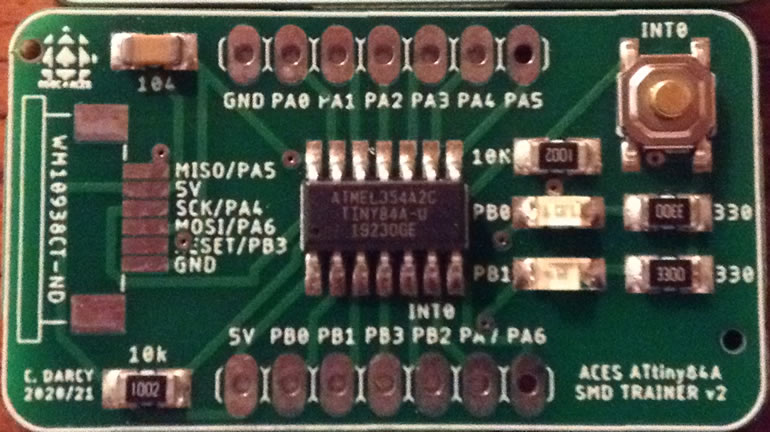
- (Training Device/Breadboard Appliance) ACES ATtiny84A SMD Trainer V3. (November 2021, JLCPCBs)
- (SMT/THT Breadboard Appliance) 4511 Viewer (April 2021, JLCPCBs, 5 pcs)
- Charlieplex Equalizer/Messager (March 2021)
- (SMT Breadboard Appliance) Benson Breadboard Adapter SMT V1 (March 2021)
- Dolgin Development Board V7 (January 2021, JLCPCBs, 5 pcs)
- ATtiny85 Function Generator (January 2021, JLCPCBs, 5 pcs)
- (SMT Breadboard Appliance) Rotary Encoder (January 2021, JLCPCBs, 30 pcs)
- (SMT Breadboard Appliance) Goldman 555 (January 2021, JLCPCBs, 5 pcs)
- (THT Breakout Board) DS1307 RTC (November 2020, JLCPCBs, 200 pcs)
- (SMT Breadboard Appliance) Truth Be Told (October 2020, JLCPCBs, 30 pcs)
- (SMT Breadboard Appliance) BB Power Adapter V4 (September 2020, JLCPCBs)
- (UNO Appliance) Morland Bargraph SMT V4 (SPI-compatible) (August 2020)
- (Training Device/Breadboard Appliance) ACES ATtiny84A SMD Trainer. (August 2020, JLCPCBs)
- (DDP Shield) Universal Shield V2 (USv2) DDP Shield for exploration ATtiny84-based features and appliances using DIP devices (August 2020, JLCPCBs)
- (UNO and DDP Appliance) SMT Assembled CharlieStick V3. (July 2020, JLCPCBs)
- (Breakout Board) Button Debouncer V2 (June-September 2020, JLCPCBs)
- Dolgin Development Board V6 (DDBv6) (March 2020)
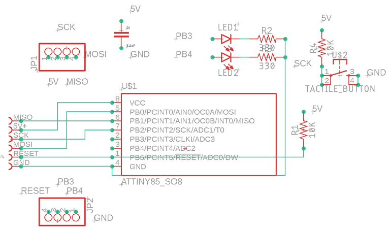
- (Training Device) ACES ATtiny85 SMD Trainer (March 2020, JLCPCBs)
- (DDP Shield) Universal Shield V1 (USv1) DDP Shield for flexible exploration ATtiny84-based features and appliances (March 2020, JLCPCBs)
- (Breakout Board) SMT Test Clip Breakout Board for in-place programming of SMT AVRs (January 2020, JLCPCBs)
- (Breadboard Appliance) Audio Spectrum Docking System (January 2020, JLCPCBs, 50 pcs)
- (Breadboard Appliance) Analog-to-Digital Conversion (January 2020, JLCPCBs)
- Line in Audio Jack Breakout Board (January 2020, JLCPCBs, 50 pcs)
- (UNO Shield) ACES CHUMP 74LS181 Explorer (January 2020, JLCPCBs)
- (UNO Shield) ACES CHUMP AT28C16 EEPROM Burner (January 2020, JLCPCBs)
- Altoids Arduino VU Meter (January 2020, JLCPCBs)
- (UNO Appliance) Serial Mastermind V3 (January 2020, JLCPCBs)
- Automatic Knight Light v2. (November 2019)
- (Appliance) SMT Charlieplex Matrix (November 2019)
- MSGEQ7 Breakout Board (October 2019)
- DES Day Counter/Equalizer October 2019 (based on earlier work of ACES' 18's D. Dadyburjor and E. Peterson)
- (UNO and DDP Appliance) SMT CharlieStick (September 2019)
- (Training Device) Binary Challenge (Summer 2019)
- Matrix Equalizer Stick V3 (June 2019)
- ISP Breakout Board V2 (June 2019, JLCPCBs, 50 pcs)
- LED Segment Tester v1 (June 2019)
- (DDP Shield) Intersection Shield for the Dolgin Development Board (June 2019)
- 2019 DC Fan (May 2019)
- (DDP Shield) Analog to Digital Conversion Shield for the Dolgin Development Board (May 2019)
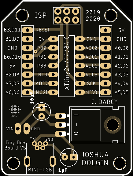
- J. Dolgin's ATtiny24/44/84 Development Board V5 (May-Sep 2019)
- (Breadboard Appliance) Benson Breadboard Adapter (April 2019)
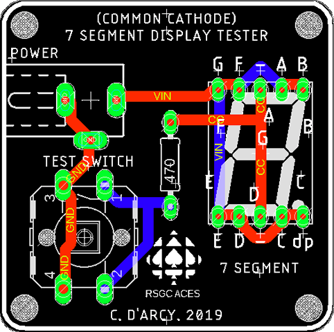
- 7-Segment Display Tester (April 2019)
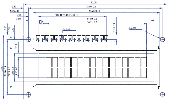
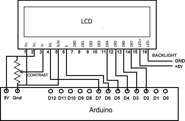
- (UNO Appliance) 16×2 Character LCD Carrier (March 2019)
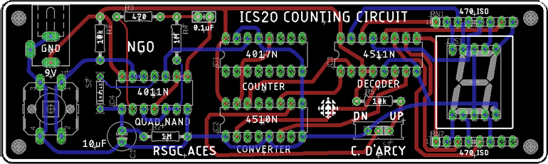
- Counting Circuit (March 2019)
- Joule Thief V0a (March 2019)
- Joule Thief V0 (February 2019)
- (UNO Appliance) Morland Bargraph SMT V2A (SPI-compatible) (February 2019)
- (UNO Appliance) UART/SoftwareSerial/SPI Communication Stick. (February 2019)
- (UNO Appliance) Morland Bargraph THT V3 (SPI-compatible) (February 2019)
- (UNO Appliance) Morland Bargraph SMT V1 (January 2019)
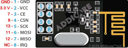
- (UNO Appliance) O. Logush's nRF24L01 Breakout Board v2. (January 2019)
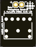
- E. McAuliffe's Photophone Transmitter and Receiver (January 2019)
- (UNO Appliance) ACES 1.8" TFT Backpack (January 2019)
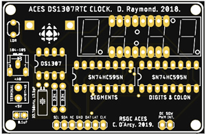
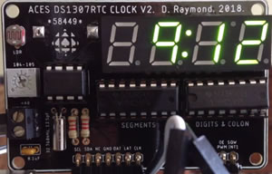
- (UNO Appliance) D. Raymond's RTC Clock (January 2019)
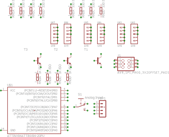
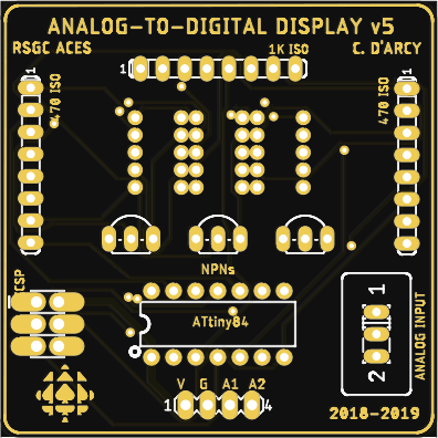
- Analog to Digital Converter (October 2018)
- Capacitor Visualizer (September 2018)
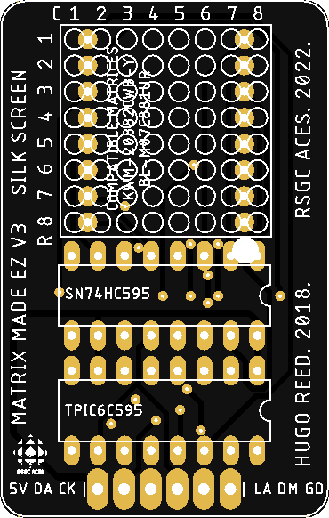
- H. Reed's MatrixMadeEZ (May 2018)
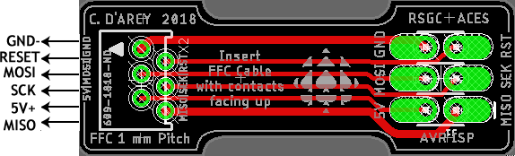
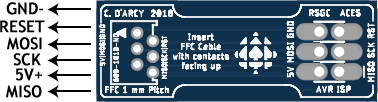
- AdapterISPFFC V2 (April 2018)
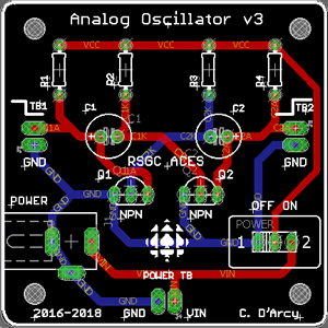
- Astable Multivibrator v2 (April 2018)
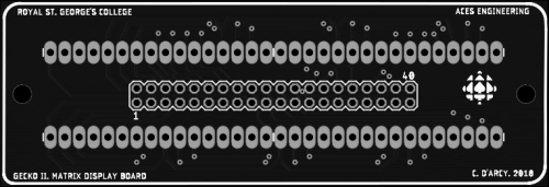
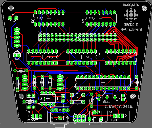
- Gecko II (April 2018)
- Matrix Equalizer Stick v1 (February 2018)
- (Training Device) Grade 5. Fergus Fidget Logic Trainer (November 2017-May 2018)
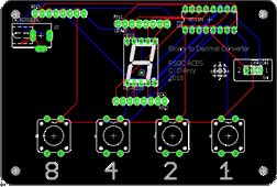
- (Training Device) Grade 5 Binary to Decimal Decoder (November 2017)
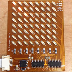
- O. Logush's Flex PCB: SMT Matrix (May 2017)
- Automatic Night Light (February 2017)
- (UNO Appliance) T. Morland's Bargraph THT V1 (February 2017)
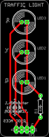
- (UNO Appliance) J. Schaffer's Traffic Light (February 2017)
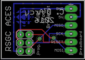
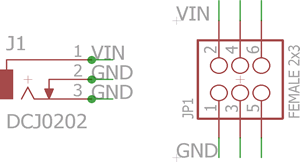
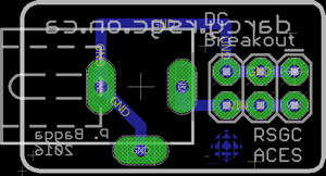
- (Breadboard Appliance) P. Bagga's Breadboard Breakout Power Adapter V3 (February 2017, January 2020)
- (UNO Appliance) Pulse Counter (January 2017)
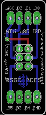
- BB ATtiny85 ISP (November 2016)
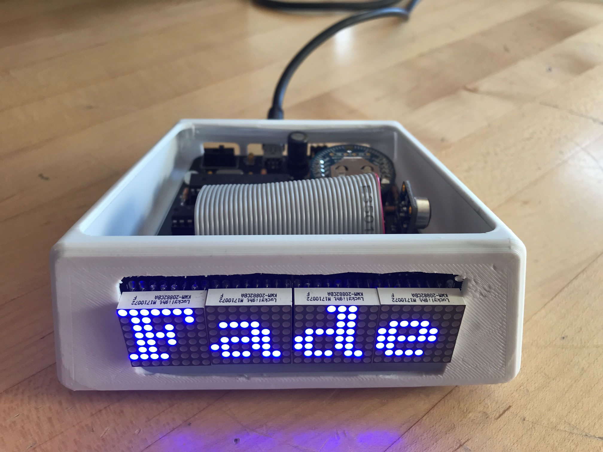
- Scrolling Message Board (March 2016. Updated March 2020)
- BB In-System Programmer (January 2016)
- BB Power Adapter (December 2015)
- Astable Multivibrator (October 2015)
- 2015 Anniversary Clock (May 2015)
- Gecko (May 2015)
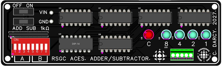
Adder/Subtractor. The third candidate for the Grade 10 Culminating Project (after the Counting Circuit and Minute Minder) is the (ambitious) Adder/Subtractor project. Adders have been a staple in the Grade 10 program for many years and its time subtraction received its due. For the capable and motivated Jr. ACE an introduction to how negative numbers are best represented opens the door to subtraction. This project will be offered for the first time in the Spring of 2027.
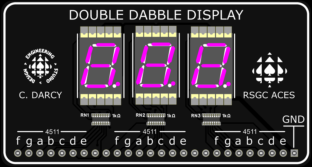 Double Dabble Display. Inspired by the 2026 revisiting of the 2019 Desktop Fan Project a breadboard appliance was created to assist Sr. ACES in their assembly language exploration of the Double Dabble (Shift-Add 3) algorithm.
The students' breadboard prototype requires three CD4511s to receive BCD input from the Nano's ports. The output of the CD4511 decoders provide the input to this PCB appliance. A common ground pin from the PCB completes the connection.
An order for 25 units was placed on March 28, 2026. To keep it neat and tidy, JLCPCB soldered everything (three SMD 7-segment displays, three 1 kΩ SMD 8-resistor arrays and a 25-pin THT male header).
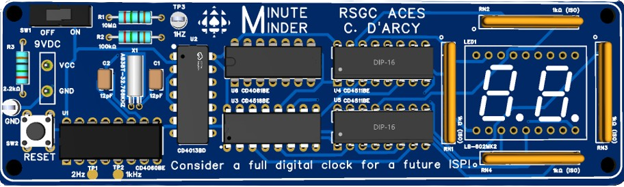
Minute Minder. A long-awaited alternative to the Grade 10 Counting Circuit project is the Minute Minder device. Inspired by an H:M:S Clock kit from Amazon this PCB stripped it down to just the seconds. The hope is that Grade 11 ACES might extend this base to create their own FULL clock as a possible ISP. Essentially this is a more accurate counting circuit driven by a 32.768 kHz tuning fork crystal (as the oscillator) divided down to 1 Hz for one second increments. The dual 7-segment display counts from 00 to 59 continuously. A reset button can restart the counting at 0. After a number of iterayions the final design for 75 pieces was submitted to JLCPCB on April 25, 2026.
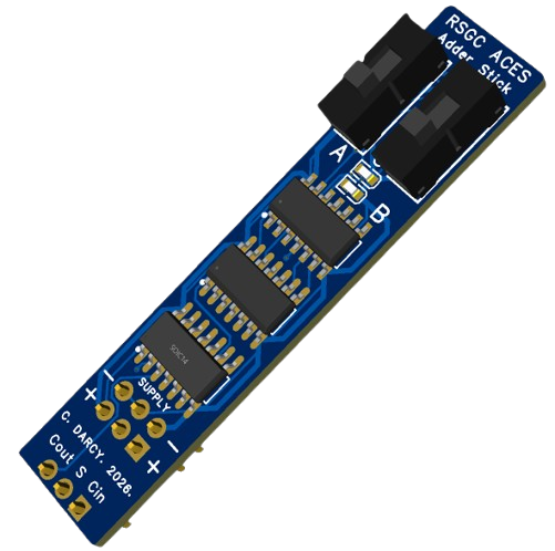
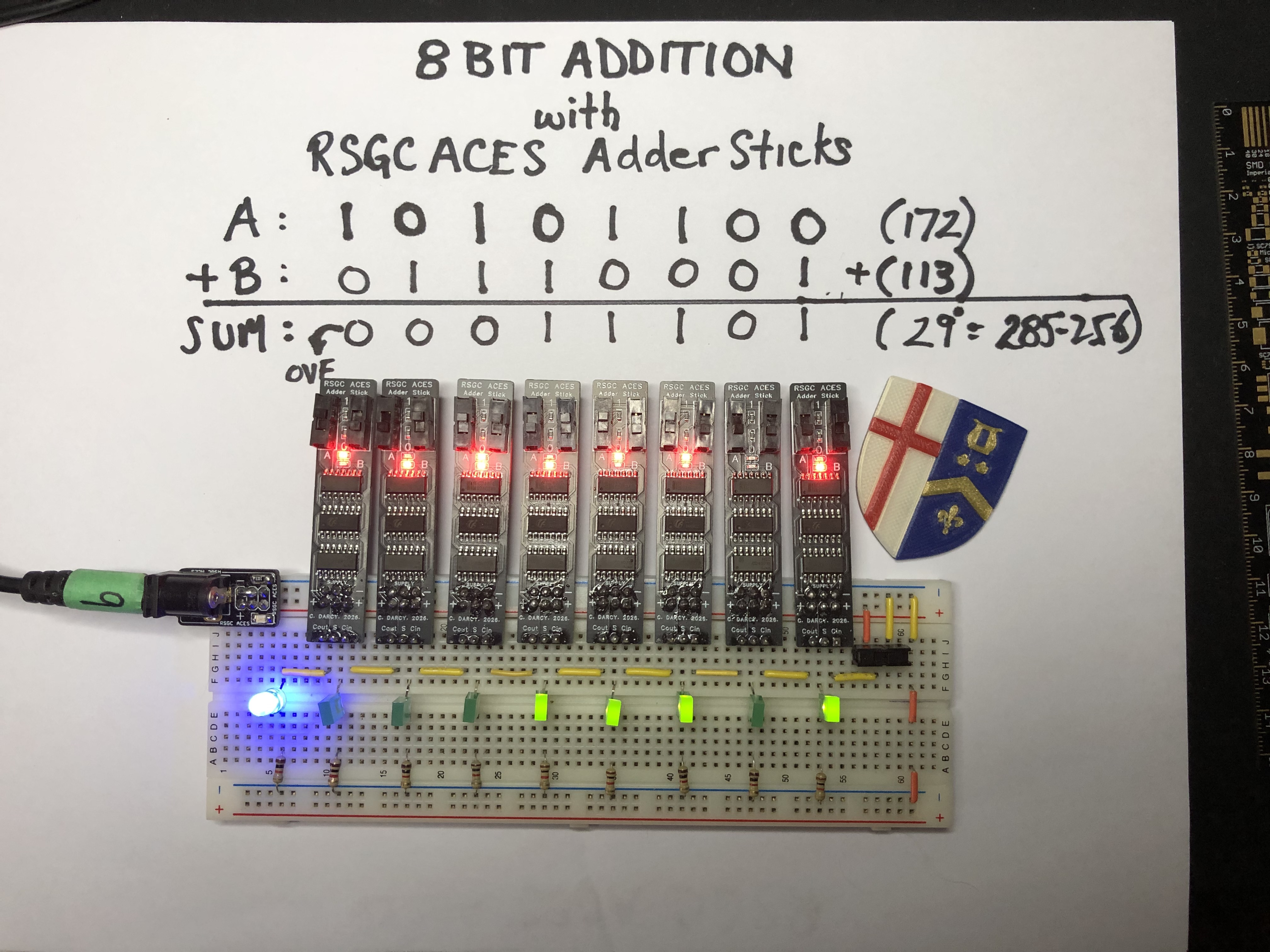
Adder Stick. A breadboard-compatible Half Adder/Full Adder device was imagined and developed expressly for Grade 10 ACES to accompany their introduction to digital logic circuits and their applications. The form factor of this device enables breadboard prototyping of both single and multiple chainable units to condition students to the concept of 4, 8, and even 16 bit register storage/memory units.
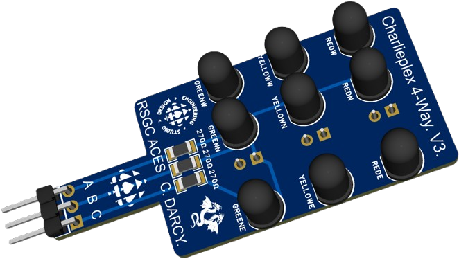
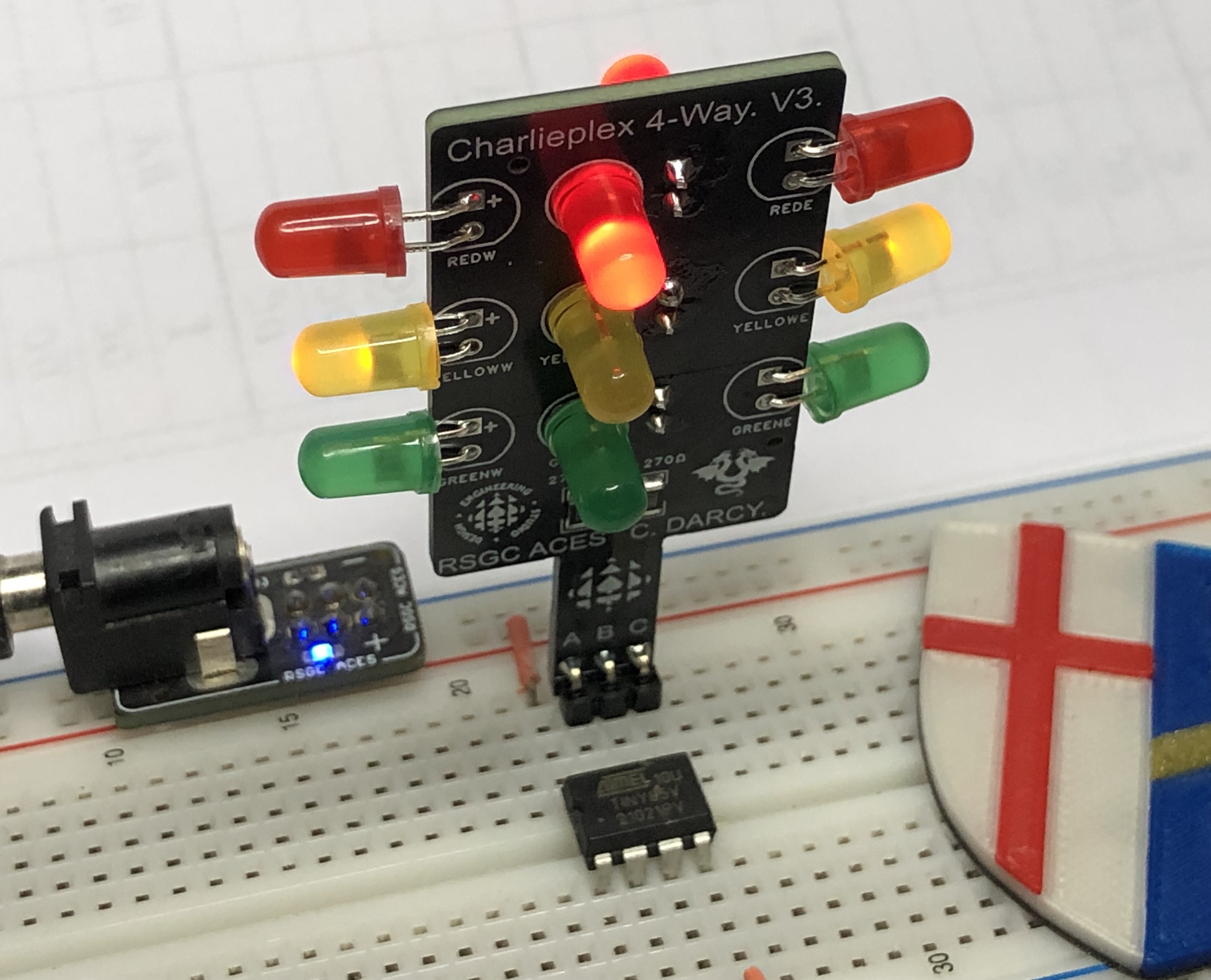
4-Way Charliexplex Traffic Light. A 4-way traffic light was developed to condition ACES to optimizing both hardware (3 pins) and software (Charlieplexed). Click here for a 30s video of the device in action. This introduction to Charlieplexing will, hopefully, inspire a Grade 12 ACE to take on the Charliexplexed Clock as an ISP.
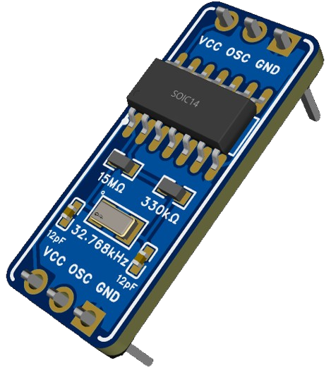
Pierce Oscillator. A 32.768 kHz crystal is the perfect foundation for our clocks. To condition ACES to handling timekeeping activities a Pierce Oscillator breakout board was developed for use in the DES.
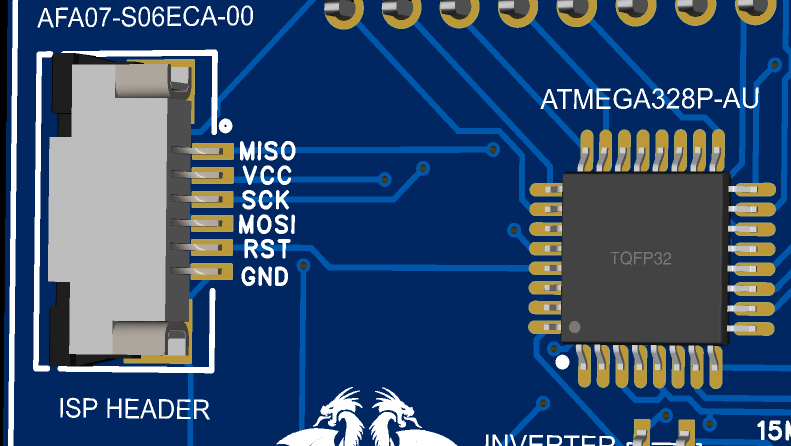
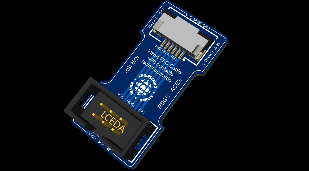
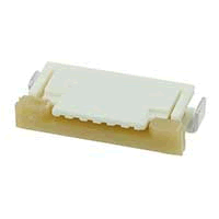
ICSP Adapter. To facilitate In-Circuit System Programming (ICSP) of the ATmega328p (all AVRS) an updated version of our previous adapter was undertaken. The standard 6-pin THT ISP header provides the input connection from Sparkfun's Pocket Programmer. The 6-position SMT connector provides the output through a flat flex cable (FFC) to a similar connector on the target PCB. 50 pieces were ordered in September 2025.
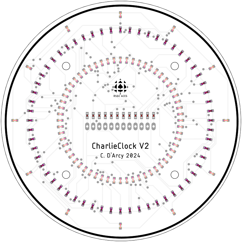
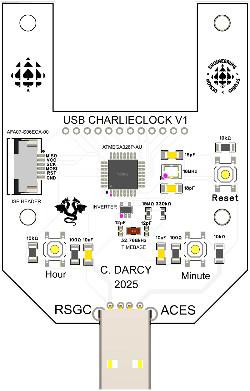
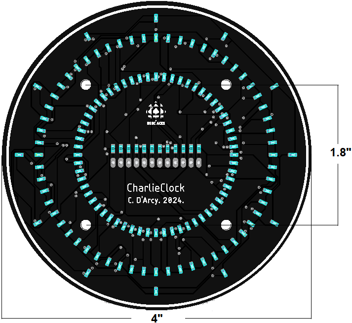
USB CharlieClock. Inspired by ACES second turn of the ICS4U-E Charlieplex Clock Project 10 pieces of the CharlieClock PCB were ordered in white. To match the face a USB-powered ALL-SMT driver board was designed and manufactured. Acrylic back and front face plates allowing students to see the circuitry up close, complete the design.
ICSP Adapter. To facilitate In-Circuit System Programming (ICSP) of the ATmega328p (all AVRS) an updated version of our previous adapter was undertaken. The standard 6-pin THT ISP header provides the input connection from Sparkfun's Pocket Programmer. The 6-position SMT connector provides the output through a flat flex cable (FFC) to a similar connector on the target PCB. 50 pieces were ordered in September 2025.
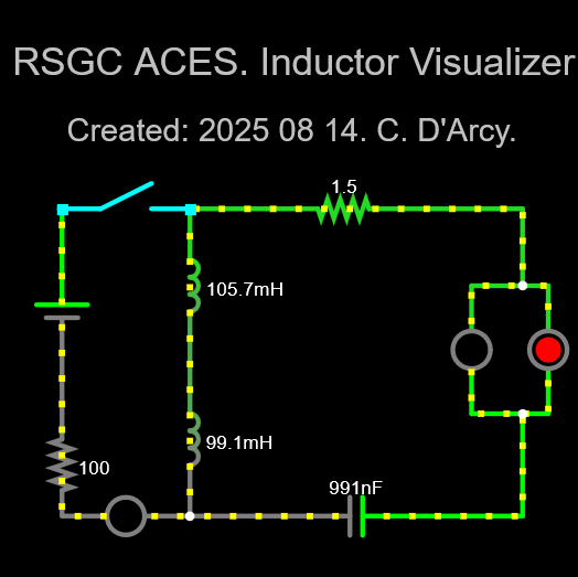
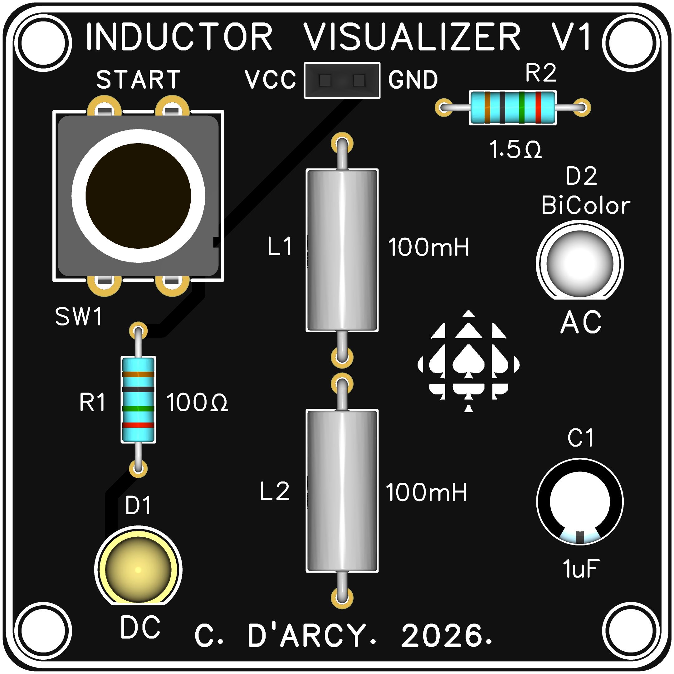
Inductor Visualizer. Together with resistors and capacitors, inductors form a set of components known as passives. Passive components can receive, dissipate, store, or release electrical energy, but cannot amplify signals or generate new ones. Based on an inductor's opposition to changing current, this component has the ability to generate voltage in the opposite direction. As such they play a crucial role in AC power circuits among others. This PCB was developed as a means for Grade 10 students to visualize the alternating current behaviour of a small signal inductor. Click on the Falstad simulation graphic below left to explore the intended action of the circuit.
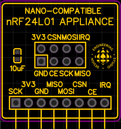
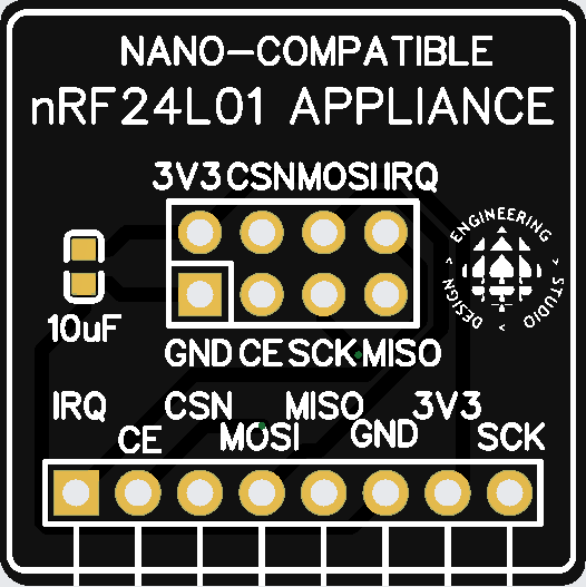
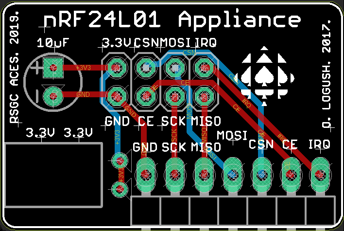
nRF24L01 Nano-Compatible Breakout Board. In preparation for the 2024-2025 ICS3U-E introduction to the wireless nRF24L01 module the previous UNO-compatible breakout board developed by O. Logush (ACES 2018, Queen's Eng. 2023) was given a Nano upgrade. Two versions of this new board were manufactured; one inward-facing and one outward-facing.
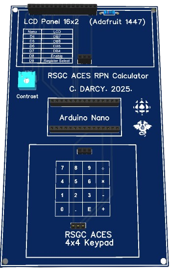
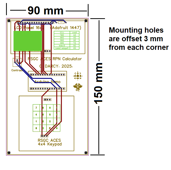
RPN Calculator Backplane. Support for the ICS3U RPN (Reverse Polish Notation) Calculator project comes in the form of a backplane into which ACES can simply insert their ACES' one-wire keypad, Nano and LCD panel. A contrast potentiometer completes the assembly. Nothing could be simpler from a rapid prototyping perspective, leaving students to focus on the interesing string and stack manipulation required to accept discrete keypad input and dynamacally evaluate the RPN expressions.
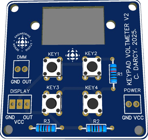
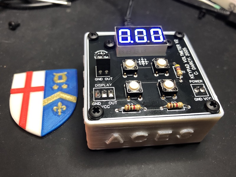
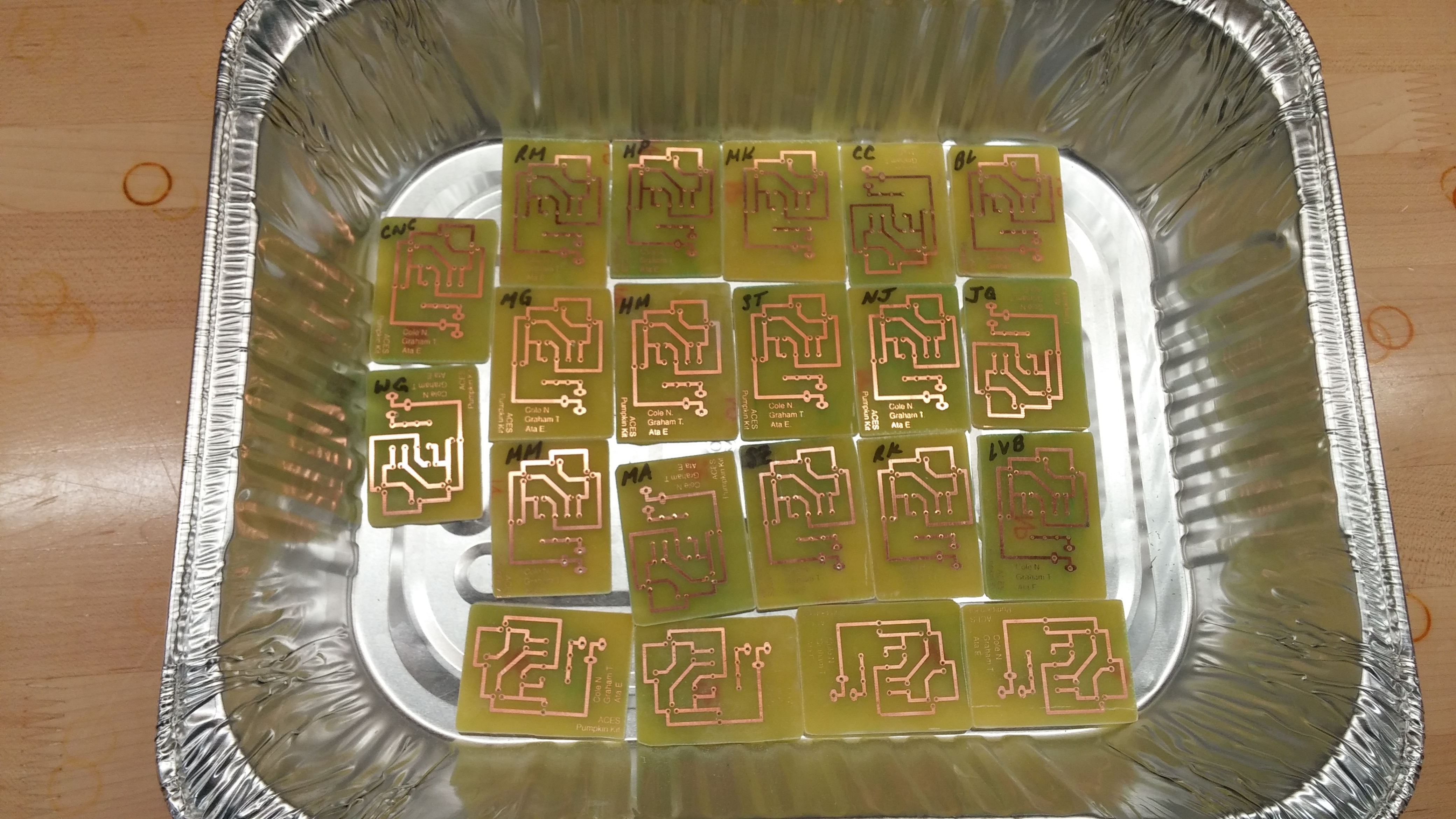
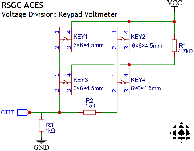
Keypad Voltmeter. A new spin on the ICD2O Voltage Division project is a 4-Button version that prepares Jr. ACES for the full 16-button calculator project in ICS3U-E. Here is the EasyEDA schematic. Relatively inexpensive voltmeters from Amazon serve to provide additional DMM support for their soldered PCBs.
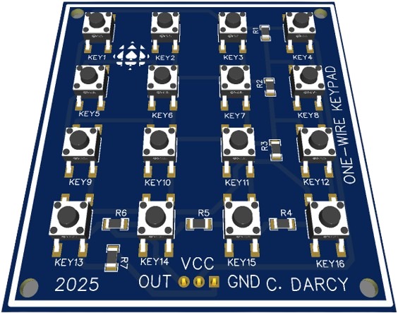
One-Wire Keypads. Whereas capacitive and mechanical keypads are readily available, the kinds of applications ACES imagine extend beyond their design and construction. To facilitate a wider range of possible projects both through hole and surface mount versions of one-wire 4x4 keypads were developed. The rationale for one-wire keypads was to reduce the demand on the MCU pins and code (library or otherwise). The development of an ACES RPN calculator for ICS3U is a distinct possibility as is an infix scientific calculator for ICS4U. We shall see....
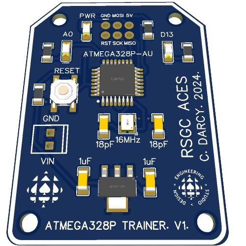
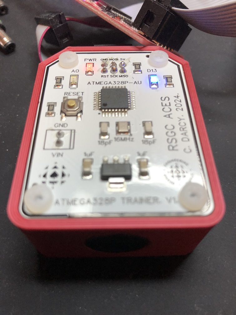
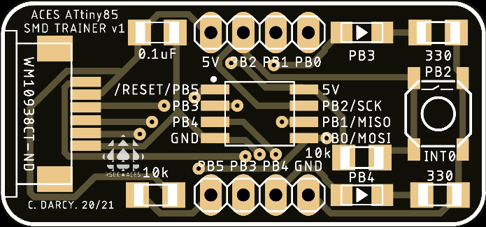
(ATmega328p SMT Trainer). By their 3rd year, ACES are ready for embedded devices with full Surface Mount Technology (SMT) features. They can arrange to have JLCPCB populate their designs or use the DES' Reflow oven. By way of a guide an ATmega328p training device was designed before handing it off to JLCPCB for manufacturing of 5 units in October 2024. Features include the TQFP-32 ATmega328p, pullup Reset button, 16 MHz crystal with 18 pF capacitors, a red power LED, a blue LED wired to digital pin 13, a green LED wired to A0, a SOT-23 5V linear regulator with smoothing capacitors, an undermounted ISP interface for ICSP programming and an undermounted power input terminal block. Where possible, the 1206 package footprints were chosen for the components in case ACES wish to do the soldering themselves. The versatile Dolgin Development PCB board outline was chosen to make use of the case design we have used on a number of previous projects. Somewhat surprisingly, Version 1 worked as expected.
(THT). With Autodesk's EAGLE scheduled for retirement in 2026 it did not make sense to introduce this Design tool to the 24/25 ICS3U-E class. Autodesk's Electronics Design replacement for EAGLE offers some tempting advantages (integration with Fusion 360) but, overall, the seamless integration of EasyEDA with JLCPCB's manufacturing backend was a combination that is hard to resist. In prepartion for the 24/25 I undertook EasyEDA's Design and Manufacturing process, ordering 5 units in early September 2024. I'll use this experience to introduce the Grade 11s to the sequence early in the course so they can incorporate the skill into their ISP.Long.
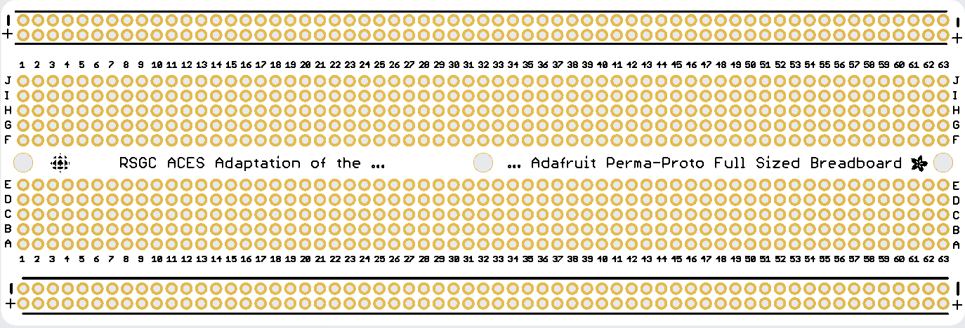
(THT Protoboard). Adafruit's full-size Perma-Proto board is a strong candidate for early ACES to transfer their breadboard prototypes to a more permanent mounting, not to mention strengthening their soldering and debugging skills. Adafruit's full-size Perma-proto is a good protoyping option but it has a number of deficiencies that needed to be corrected. The first issue is the distance between the prototyping area in the center and the nearest power rail. The breadboard gap is 0.3" which is the orange jumper in DES use. The second is the number of columns of prototyping area. The breadboard offers 63, whereas Adafruit's offers 60. The third issue is the position of the mounting holes that do not align with the holes on their half-size boards, denying the possibility of stacking boards with standoffs. The final issue is price. At 15$CAN ish, Adafruit's full-size perma-proto is simply too expensive. Our ACES version of Adafruit's board is shown below with these shortcomings addressed. An order for 100 ($2/pc) was placed in May 2024 and ready for use in the Fall of 2024.
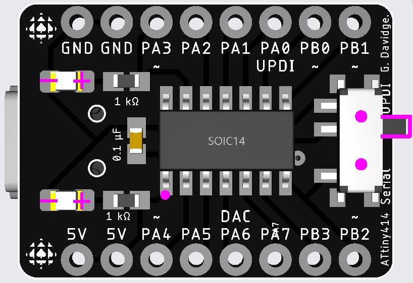
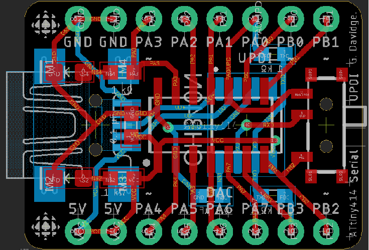 (Training Device/Breadboard Appliance) Davidge ATtiny414 Development Board. The latest instalment of an ACES Development Board is the product of G. Davidge's (ACES' 24) third ICS4U-E ISP. This breadboard-compatible board features the ATtiny414, a member of Microchip's relatively new series of ATtiny MCUs. This line of devices feature a surprisingly rich selection of built-in peripherals at a very attractive price of under $2.. The primary drawback for ACES is that this new line of MCUs is only available in SMD packages, hence the need for this mounted development asset.
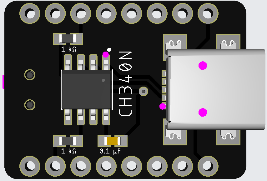
Davidge's board features a double-sided SMT design with the CH340N USB-to-Serial IC mounted on the bottom. This permits ACES developers the luxury of working within the Arduino IDE whiles retaining access to the Serial Monitor and Plotter. Two 8-pin male headers complete the Nano-esque style form factor.
Additional features include an onboard switch enableing the option of either (2-wire) Serial or (1-wire) UPDI programming. A power LED and an onboard LED attached to PA3 round out the assets.
Mac Driver: https://www.wch-ic.com/downloads/CH341SER_MAC_ZIP.html
Windows Driver:
https://www.wch-ic.com/downloads/CH341SER_ZIP.html
Charlieplex Clock. ACES enjoy a rich history with Charlie Allen's discovery back in 2001. Charlieplexing offers both a practical and creative use of your MCU's tri-state digital pins and ACES have developed a number of devices that exploit its features (ie. CharlieStick, CharlieplexEqualizer). The 2022/2023 ICS4U-E ACES had the notion late in their year to develop a clock based on the principle and, although they scrambled at the end of the year to realize it, the course ran out and it was off to summer and univeristy without crossing the finish line.
With a final three-hour class imposed upon the 2023/2024 ICS3U-E class, it was decided that an LED Charlieplex Clock was too irresistable to let sit on the drawing board for much longer. Mr. D. developed the PCB in late April and had JLC manufacture and populate 20 PCBs with 132 0603 LEDs (60 Red/Seconds, 60 Green/Minutes) and 12 Blue/Hours) in time for the final class of the year. Imagine, 132 LEDs driven by 12 tri-state digital pins. So good! Four mounting holes offers the motivated ACE the chance to develop and mount a driver circuit on the back or the front, over the summer. Hmmm.... come to think of it, digital date information would be a terrific complement to the analog time display. Furthermore, a stepper motor could rotate the day of the week into view, as do the Rolex. Finally, a Fusion360 designed case would be a natural design enhancement. We'll see what my 2024/2025 ICS4U-E ACES show up with in September. They seldom disappoint :)
(Programmer) Unified Program and Debug Interface. The newest geenration of ATtiny MCUs from Microchip have dispensed with ICSP programming in favour of a 1 wire proprietary strategy referred to as the Unified Program and Debug Interface, or UPDI for short. Commercial UPDI programmers are available (eg. UPDI Friend) but ACES' need our own. 5 units were ordered from JLCPCB on March 12, 2024. More information on this project can be found here.
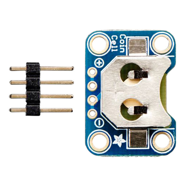
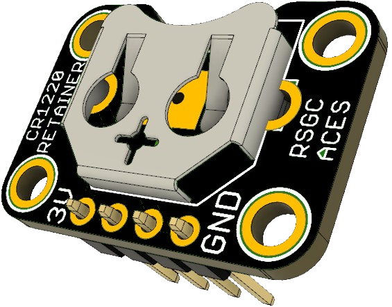
(THT) CR1220 Coin Cell Retainer. In preparation Term 2 of the 23/24 ICS3U-E iteration's Tiny Clock project a small, breadboard-compatible THT CR1220 coin cell retainer was adapted from Adafruit's 1868 design.
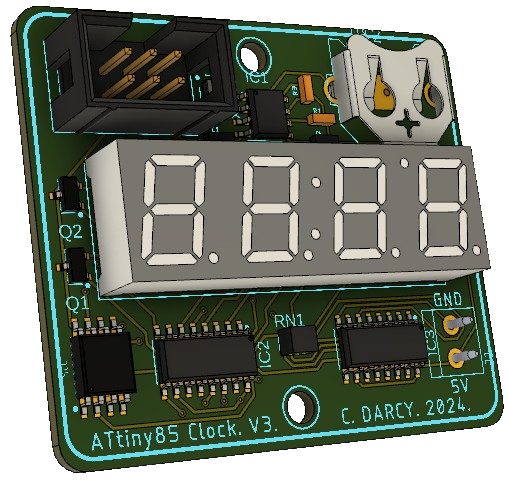
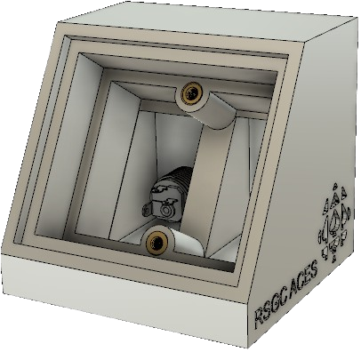
(SMT) ATtiny85 Clock. In preparation Term 2 of the 23/24 ICS3U-E iteration a small SMT ATtiny85-based clock was developed and confirmed over the Christmas holidays. Students have the 4-digit 7-segment COM-09481 CA display in their kits which pairs nicely with their THT ATtiny85 and THT DS1307 RTC ICs. The PCB was sized to match Adafruit's quarter-size perma-proto board to allow for easy mounting on the Fusion360 designed ACES' Display (below, right).
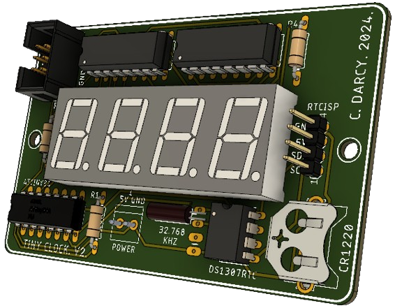
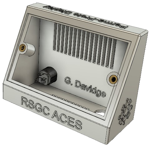
(THT) ATtiny84 Clock. In preparation Term 2 of the 23/24 ICS3U-E iteration a THT ATtiny84-based clock was developed and confirmed over the Christmas holidays. The PCB was sized to match Adafruit's half-size perma-proto board to allow for easy mounting on our Fusion360 designed ACES' Display.
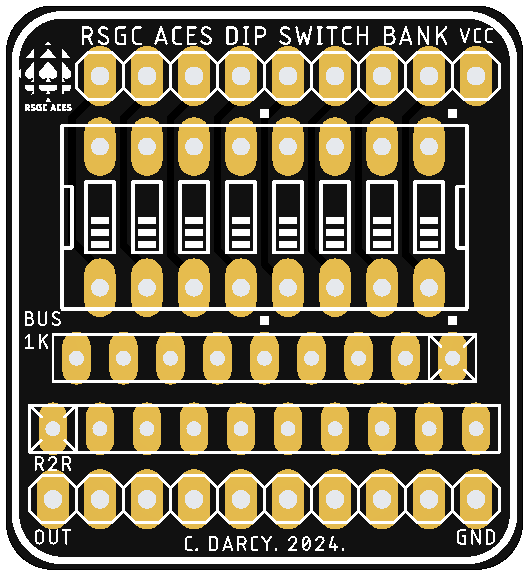
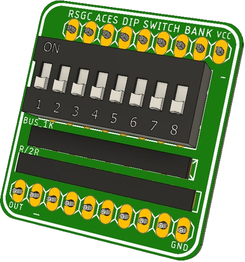
(THT Breadboard Appliance) DIP Switch Bank. This dual purpose device offers 8 convenient DIP rocker switches in an pull down (Open) configuration designed to support breadboard prototyping, An onboard R/2R network ladder can also be exploited for applications requiring an 8-bit DAC input.
Received 2023 11 13. Soldered, tested and confirmed. Here's a photo of the device wired up: http://darcy.rsgc.on.ca/ACES/TEI3M/Photos/DIPSwitchBankPCB.jpg
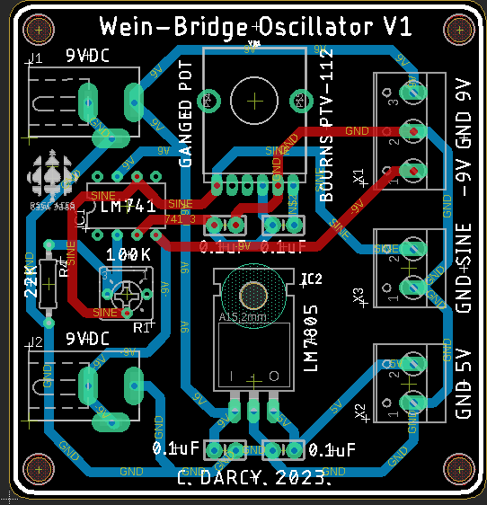
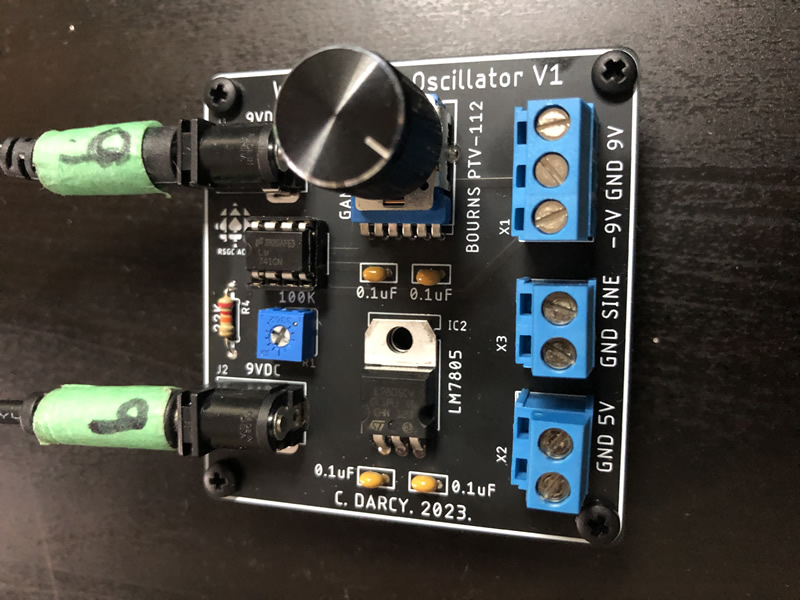
(THT) Wien-Bridge Oscillator V1. ACES' increased use of Operational Amplifiers (Op Amps) in our upper years drove the need to develop an accessible supply source for both +9V and -9V. The solution was to employ two 9V AC/DC Wall adapters by tying the negative terminal of the first to the positive terminal of the second, creating a common reference voltage (GND) for the remaining terminals (one a positive potential difference and the other a negative PD). The first project to exploit the new asset is the SAR ADC project described here at Hackaday: https://hackaday.io/project/181826-homemade-successive-approximation-register-adc
In addition to simply supplying +/-9V and a reference GND, It was decided to place an Op Amp application on the PCB as well. The Wien-Bridge Oscillator generates a sinusoidal wave form that is also a handy asset for ACES project ends. Here is a good video on the WBO:  Wien-Bridge Oscillator
Finally, adding a 5V regulator to the PCB complements the supply levels as many projects combine multiple supply levels.
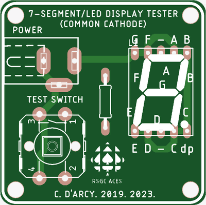
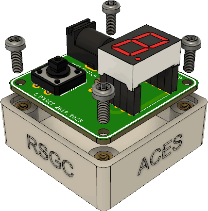
(THT) ACES LED Tester. After years of using an commercial LED Tester from Velleman and a custom device from S. Appleyard in 2022, it was decided to create a simple LED Tester that we could reproduce and Grade 10 students could solder with relative ease. The result is the ACES LED Tester that can confirm discrete through hole LEDs and common cathode (CC) 7-Segment display.
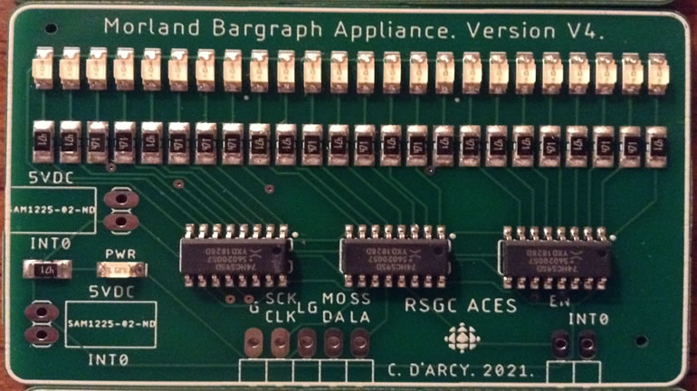
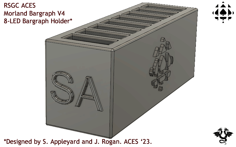
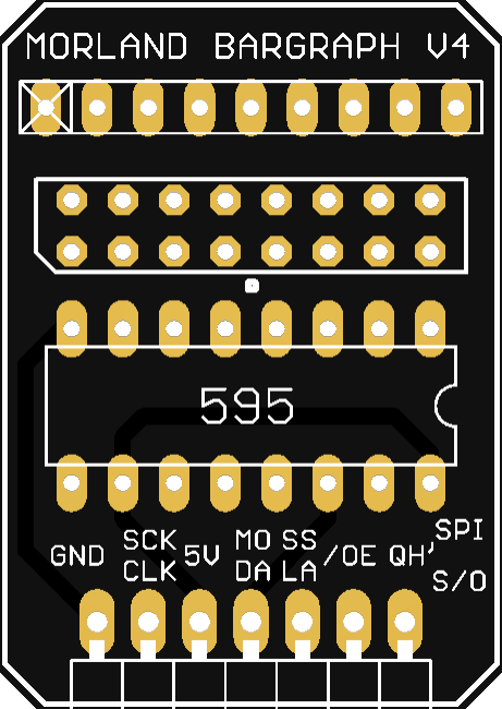
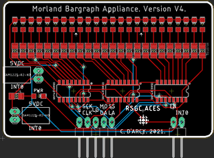
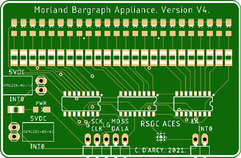
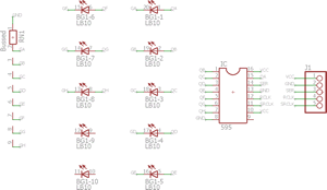
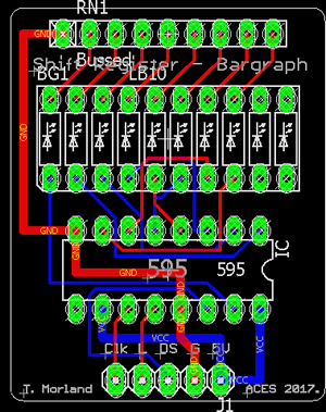
(THT) Morland Bargraph V4. This is a long overdue and significant update of the 2019 version of our Morland Bargraph. It has been a long-held DES dream to design and implement our own bargraphs and, finally, the ACES' 2023 design team of S. Appleyard and J. Rogan achieved just that. An RSGC ACES 8-LED shorter bargraph device version eliminates the hotdog/bun inequity of 595/10-LED bargraphs for all time! In addition, the MBV4 breaks out the 595's Carryout pin to allow for the chaining of multiple MBV4s.
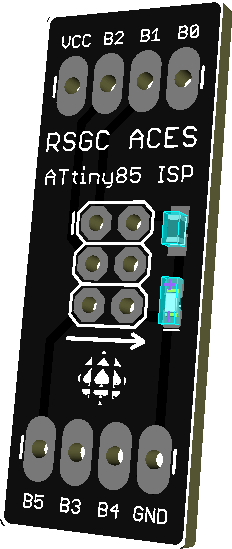
ATtiny85 ISP BoB V2. This is an update of the 2016 version that includes onboard SMT Power LED and resistor. 30 units were ordered from JLCPCB on 2023 01 04 ans 100 more on 2023 12 26. To alleviate the hassle of wiring our earlier ISP breakout board, this device is conveniently-placed over top of the ATtiny85. P. Bagga suggested the use of female stackable header pins to make subsequent prototyping even faster. Good call, unfortunately, 4-pin stackable headers were hard to find but, in the end, a slow boat from Taiwan delivered 200 units :) 2023 01 04: ABRA now stocks them, too!
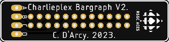
ACES 12-LED Bargraph Holder. A request went out over the 2022 Christmas Break to our ACES '23 Fusion360 Team (J. Rogan and S. Appleyard) to design a 12-LED holder for rectangular LEDs. Within 48h the design was complete and JLCPCBs were printing 15 units. These 'trays' can be used to create standard, bicolor, or Charlieplex variants for metering applications. Slot dimensions are 5.1 × 2.1 × 7.5 mm designed for Lite-On's LTL-433G, LTL-433G, and LTL-433HR LEDs, as well as Kingbright's WP117EGWT Bicolor LEDs. 500 units of each were ordered from Mouser on 2023 01 03.
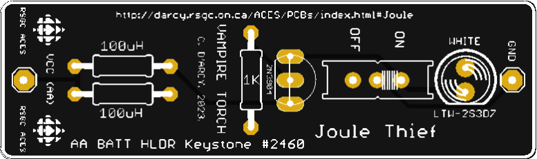
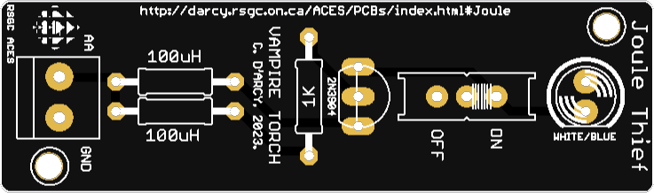
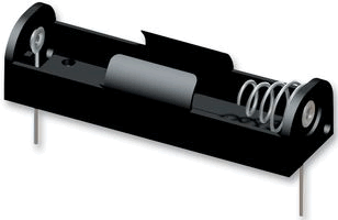
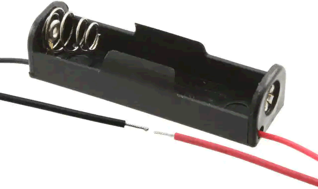
Joule Thief. A redesign of an earlier attempt of the Joule Thief in 2019 was undertaken in January 2023. Two versions were ordered from JLC to accommodate different variations in the Keystone battery holders as shown below.
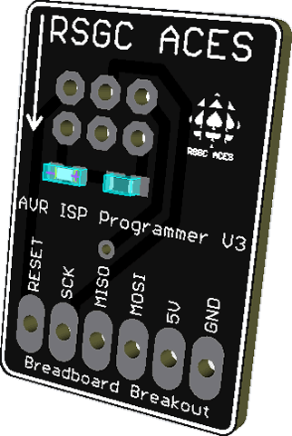
ISP Breakout Board V3. A small upgrade of the V2 version sees a blue 0603 power LED light up to confirm the correct orientation of the SAPP cable.
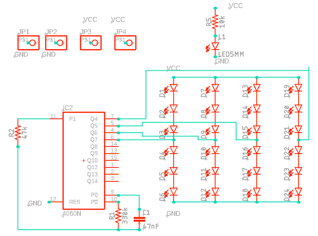
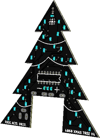
ACES XMAS Tree and Stand (January 2023). After years of enjoying Velleman's 3D Christmas Tree, it was time a custom ACES tree was developed. Five units of V1 were ordered and worked as designed. A V2 was developed but never ordered before it was decided to increase the number of LEDs in each string to four from three. Rather than using an astable multivibrator as the base for oscillation, the 4060 ripple counter IC was employed as suggested by this tutorial. A mixture of THT and SMT components are incorporated. For the top ornament the 5mm diffused RGB LED from Adafruit was adopted. S. Appleyard (ACES '23) has offered to design a custom 9V battery holder/stand that we will have CNC milled by M. Elia (ACES '15) of Argon Prototypes. Perhaps a 3D resin-printed diffused star to fit over the LED might eventually top off the project?
|
|
 |
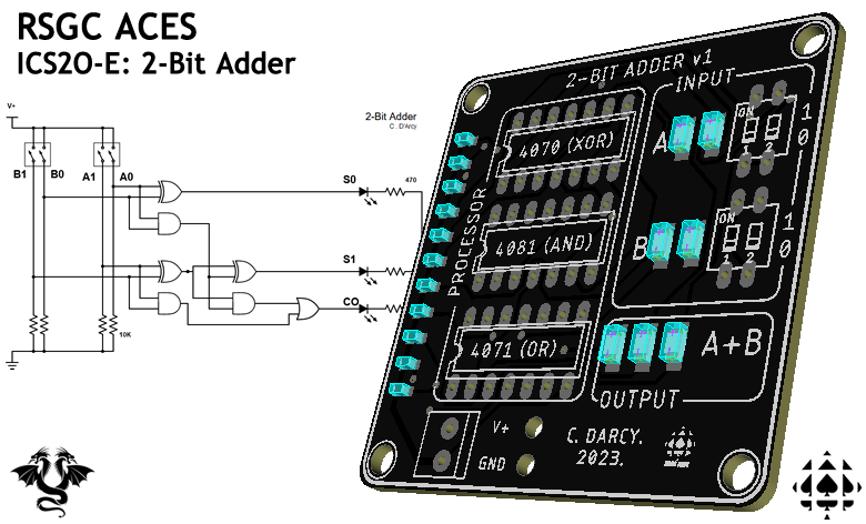
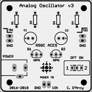
2-Bit Adder (December 2022). Logic circuits are the backbone of digital computation. This important combinational logic circuit introduces 1st-year ACES to itits application to digital arithmetic. The PCB implements a half-adder and full adder to enable the user to emulate the addition of a pair od 2-bit operands. In addition to one of their first exposures to digital logic principles, the insights into broader computer engineering concepts it affords young ACES is inspiring for them. Furthermore, the Grade 10s revisit and strengthen their soldering skill set. THe 2-bit adder joins an increasing number of 2" × 2" PCB designs, purposely dimensioned to fit our generic ACES case originally designed for both the Capacitor Visualizer and Analog Oscillator PCBs.
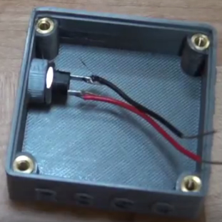
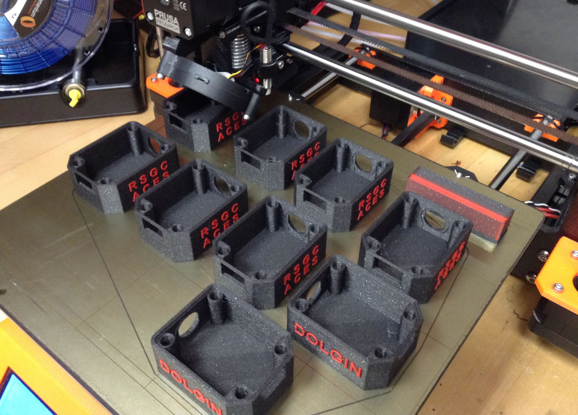
Nut Pockets. The compelling use of JLCPCB's relatively inexpensive 3D printing service has resulted in a modified design for fastening PCBs to our enclosures. Since SLA (resin-based thermoset) plastic does not lend itself to our preferred use of heat set inserts, an alternative strategy was called for. Nut pockets as shown below were designed into our RSGC ACES Perma-proto stand to accommodate both the M3 screw/hex nut combination as well as the hex nut for the panel mount PBNO Reset switch. A further advantage is the elimination of the heat set installation. An order for 5 of the stand design below was placed with JLCPCB in March 2022. We shall see if this design decision results in what we set out to achieve...
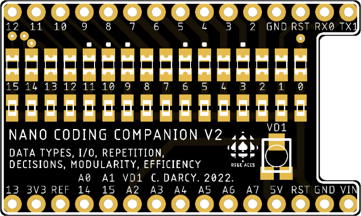
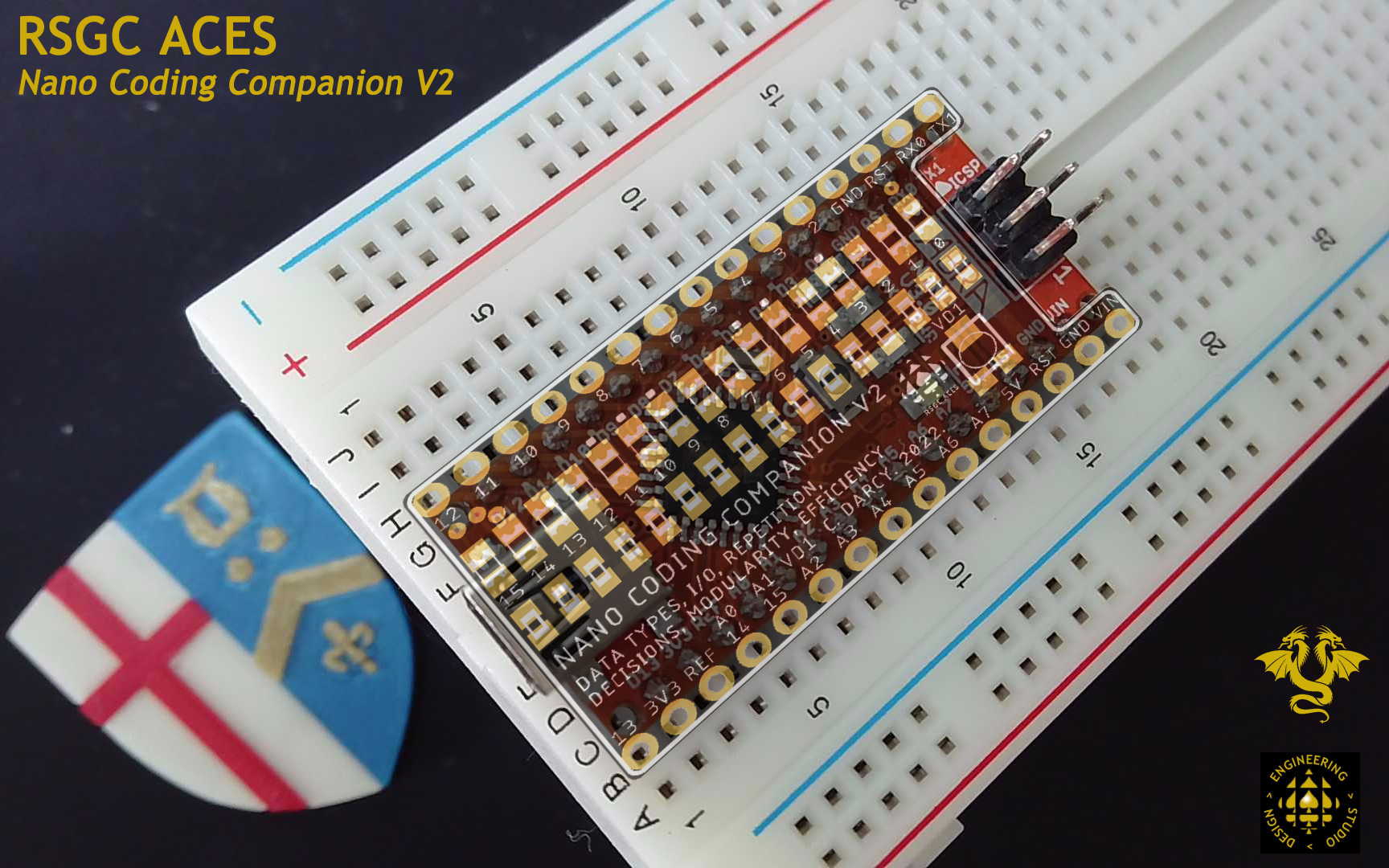
ACES Nano Coding Companion. Despite this province's efforts to promote coding as an esseantial skill throughout Grades 3-9, the current coding skill level of students entering ICS3U is not where it needs to be to successfully engage the hardware expectations of Grade 11. My active solution to the problem in early 2022 was to developed a breadboard appliance PCB intended for immediate introduction at the start of the 2022/2023 ICS3U course. As a 'breadboard appliance' no supporting wiring is required to immediately condition ACES to the findamental coding concepts of data types, input/output, loops, decisions, modularity, efficiency and documentation. The Nano Coding Companion fits over their Nano and programmed with their Sparkfun AVR Pocket Programmer. On the output side, the NCC breaks out 16 of the ATmega328P's digital pins (0-15) to Blue SMT 0805 LEDs. For input, a Bourns SMT 5 kΩ Trimpot (JLCPCB Part #C124626) provides variable voltage into A2.
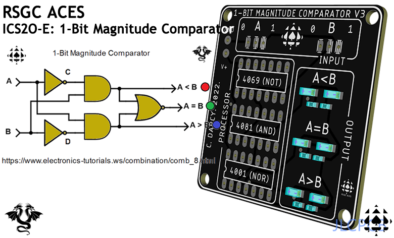
1-Bit Magnitude Comparator (April 2022). Logic circuits are the backbone of digital processing. This interesting combinational logic circuit compares the relative magnitude (rank) of the two single binary inputs. In addition to their first exposure to digital logic principles, the insights into broader computer engineering concepts it affords young ACES is inspiring for them. Furthermore, the Grade 10s revisit and strengthen their soldering skill set. This 1-Bit Digital Comparator circuit is modelled after this tutorial. An RGB LED output indicator was required in the prototype project, reflecting the relative rank of single bit binary inputs. In this PCB implementation, three bicolor LEDs serve as separate outputs. The 2" × 2" PCB was purposely dimensioned to fit our generic ACES case designed for both the Capacitor Visualizer and Analog Oscillator PCBs.
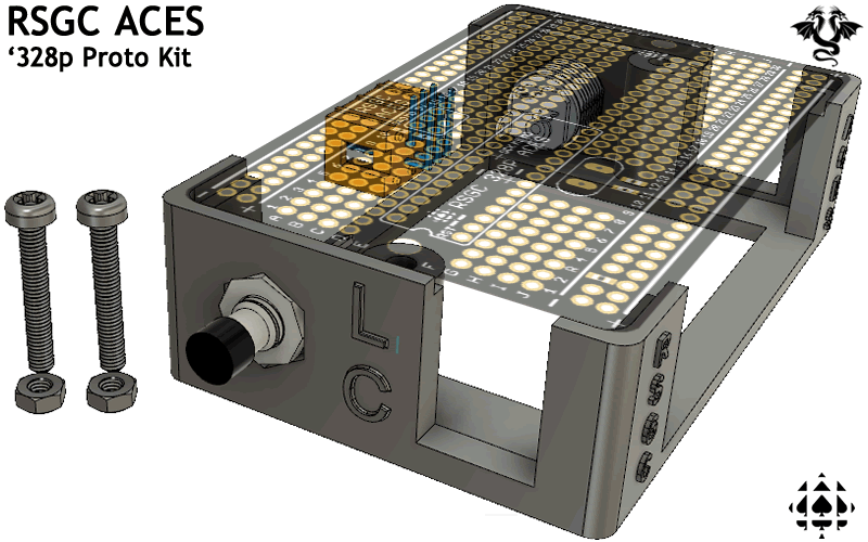
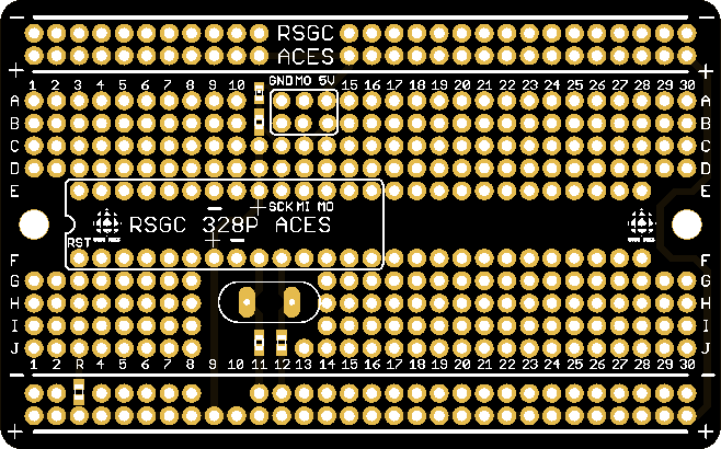
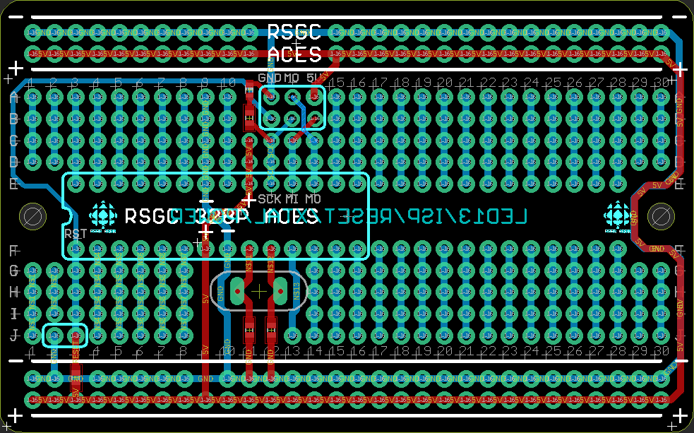 ACES '328P Perma Proto Kit: Half-Size PCB V2 (ISP/Reset/LED13/Caps) with Augmented Stand (February 2022, JLCPCBs). The relative success of the 2021/2022 ICS3U-E Perma-Proto project inspired continued development. On the PCB side, attempting a right balance between support for the ATmega328P and the students' latitude for their project parts' placements, additional practical and aesthetic PCB assets were introduced. The onboard LED is mapped to Pin 13 (as per the UNO and Nano) but can be adapted for any other purpose. Support (traces) for the undermounted Wurth Shrouded ISP header is added. An onboard 10 kΩ pullup resistor on the Reset (Pin 1) is included. Pads for the soldering of an HC-49S 16 MHz crystal were added. A pair of onboard 0603 20 ρF crystal capacitors were added. Power rail pairs have been connected (additional wires are recommended for higher current draws). Vias in the vicinity of the mounting holes were removed for improved assembly.
On the Stand side, apertures for the Schurter 2.1 mm Power Jack and a standard SPST PBNO Momentary switch were added. More significantly, nut pockets were introduced as a substitute for the use of heat set inserts (HSIs). The reason for this is the compelling case for having JLCPCBs produce class sets of these stands. Their resin-based thermoset technique does not lend itself to the post-production application of HSIs. On top of that, ACES should no longer rely on TAs to support the design ambitions of younger ACES, but the cost of printer maintenance and supplies, in terms of time and money, is becoming a challenge.
| ACES '328P Perma-Proto Half-Size V2 (ISP/Reset/LED13/Caps) |
ACES '328P Proto Kit (Half-Size V2 on Equipped Stand) |
|
 |
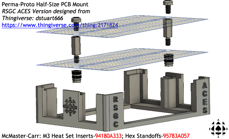
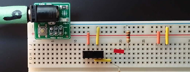
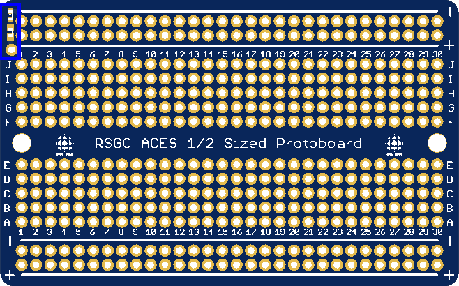
ACES Perma-Proto Half Size V1 (January 2022, JLCPCBs). Over the extended Covid (Omicron) Christmas break of 2021 preparations were undertaken for the Spring session of ICS3U that includes an encased ATmega328P embedded project. To facilitate completion of the project, assets shown below were developed from available open source designs. A less expensive ACES version of the popular Adafruit half size perma-proto board was developed that features a SMT 0603 LED/Resistor pair for optional use by students. Fifty SMT assembled units from JLCPCB were ordered in December 2021 (I was informed they felt gold was the way to go with so many holes but they couldn't do Black so I opted for Blue). In addition, yet another run at design success using Fusion 360 was undertaken as well that yielded a variation of a similar versatile design found on Thingiverse. With the help of our 21/22 3D printing TAs, units of the latter will be ready for use in February 2022. To increase overall board area spacers can be used to stack perma-protos. Male headers can be soldered to link signals between the PCBs.
| JLC Rendering (click to enlarge) |
Perma-Proto Half Size Mount |
|
 |
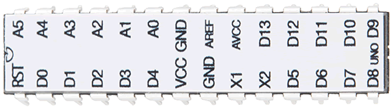
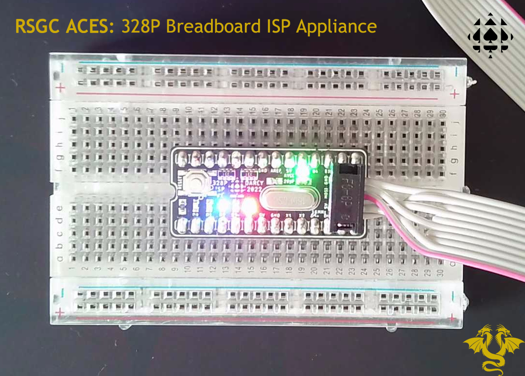
ACES ATmega328P ISP Breakout Board (January 2022, JLCPCBs). In the style of previous overlaid appliances designed to expose an IC's capabilities with minimal supporting breadboard componentry (Truth Be Told, 4511 Viewer) this latest device facilitates an ICS3U introduction to a standalone MCU prototype in the simplest possible manner. A mixture of SMT and THT headers (JLCPCB is currently out of stock of 16 MHZ SMD crystals) combine to enable the developer to flash code using their Sparkfun Pocket Programmer. A handful of onboard 1206 LEDs can be used to confirm code validity.
2021 12 22: 5 units arrived from JLCPCBs today. Soldered 'em up and they perfom as designed. Whew :).
Confirmation. Arduino Test Sketch: BlinkonUNOAVRProgrammer.ino
2022 09 10: Reordered 25 units (V2: 16 MHz) from JLCPCB
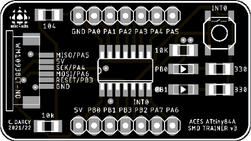
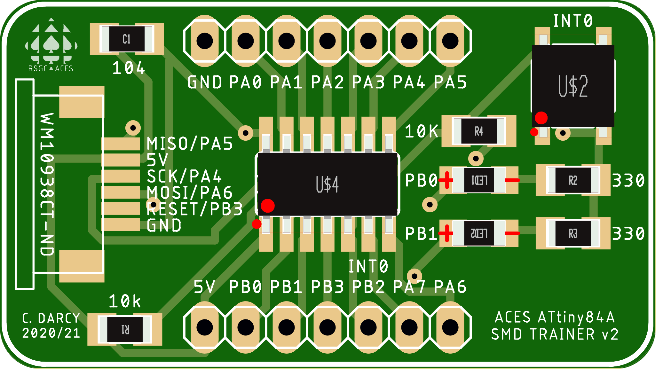
ATtiny84A SMD Trainer V3. A correction to the Reset Line prompted the reordering of V3 of this board. Upon receipt X. Chin (ACES '22) baked three samples in the DES reflow oven (created by A. Hodgson ACES '19). Subequent testing revealed it is good to go for student training efforts.
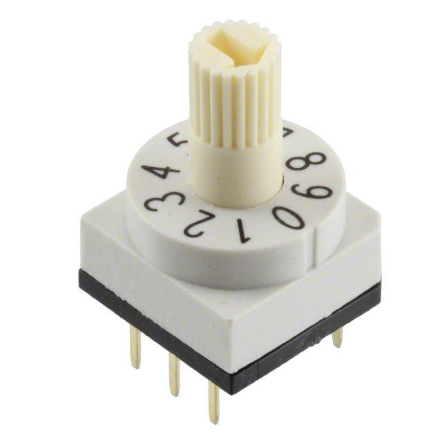
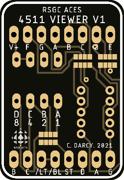
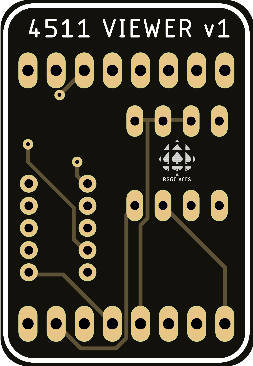
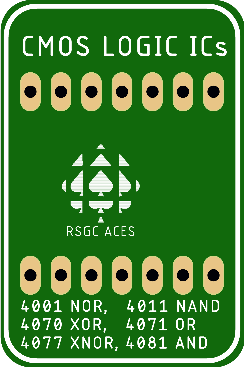
4511 Viewer. Just as the Truth Be Told breadboard appliance offered the Grade 10 ACE visual confirmation of the truth table for a number of 4000 series of CMOS Logic ICs so, too, does the 4511 Viewer offer similar savings when exploring this BCD to 7-segment display driver IC. After an interesting conversation with a Grade 10 student the idea for the PCB becamse obvious. A 4-position SPST DIP Rocker switch would permit the operator to simulate BCD input, which the 4511 will decode and present on the ROHM LA-301 7-segment display. SMT DIP resistor networks support the small form factor of this PCB. Should this PCB function as expected, JLCPCB would handle the soldering of the DIP switch from their own THT inventory ( Something like this)
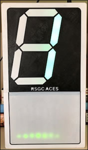
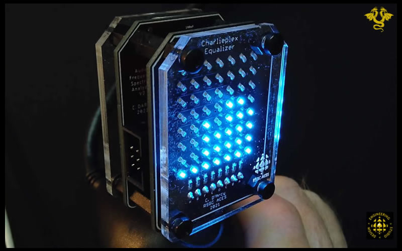
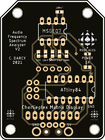
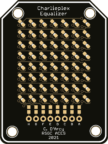
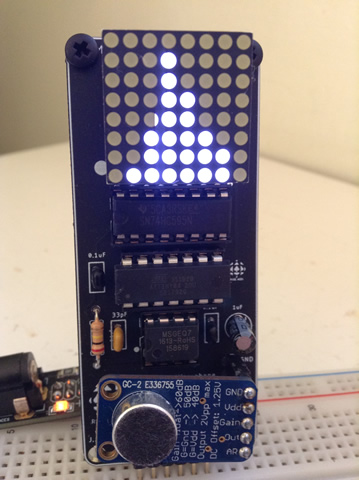
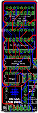
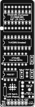
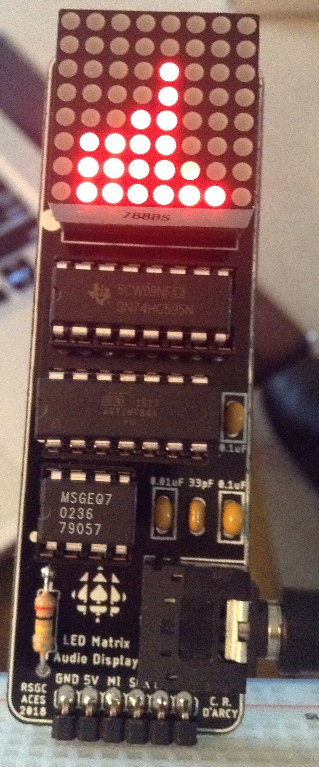
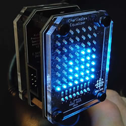 Charlieplex Equalizer/Messager. (March 2021). It has become a fact of life within the ACES program that every two years or so, developments and opportunities have evolved so much that a new device is required to crystallize the accumulation of achievements. The outsourcing of SMT assembly services has made possible the current iteration in the form of a compact unit that acquires ambient sound, passes it through a 7-band frequency analyzer, and presents the spectrum, dynamically, on a 8×7 Charlieplex matrix. ACES' preference for the ATtiny84 (as a balance between size and capability) provides the coordination of the MAX9814 AGC MIC, MSGEQ7, and display matrix. The library-free, register-level software employs interrupts to switch between the audio responsive display and a scrolling message from our sponsors every 10 minutes :) Here's a short video clip.
Benson Breadboard Adapter SMT V1. (March 2021). A long overdue upgrade to Graydon Benson's (ACES '19, Calgary '24) uniquely popular through hole version was enabled by JLCPCBs' sensibly-priced SMT Assembly services. Aside from our preferred THT DC Jack and two male headers, the balance of the components was sourced exclusively from JLC's inventory. A test run of 5 confirmed the devices' functionality. The single modification in the subsequent order for 50 (JLC's maximum for SMT Assembly) was a 22 kΩ power LED resistor to replace the 1 kΩ (it was too bright). Very handy little appliance. Click image to enlarge. Thanks, Graydon!
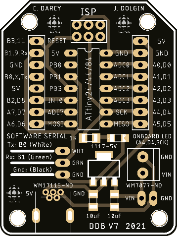
Dolgin Development Board V7. Designing increased utility into the DDB's familiar form factor is an ongoing pursuit. To free up INT0 on D8 (PB2) the onboard SMT LED was moved to D4 (PA4/SCK) with 1 KΩ series resistor (similar to UNO). SMT voltage regulation replaced the larger THT LM7805 TO-220 which yielded space for a power access terminal block.
 . |
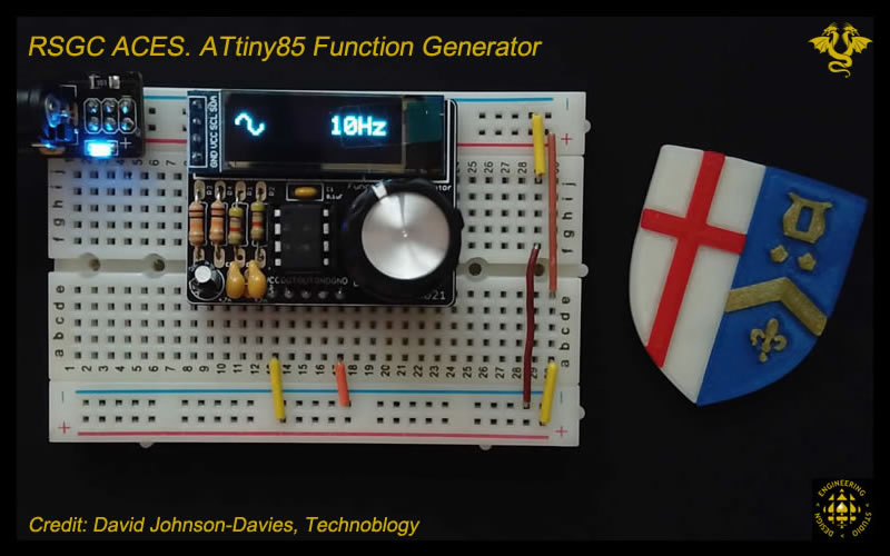
Function Generator. After reviewing the compelling Function Generator project from David Johnson-Davies of Technoblogy, a modified design from his EAGLE files was created and a small order of 5 pcs from JLCPCB was commissioned in January 2021. Upon receipt of the PCB, the device was assembled and tested. The results were captured on our scope and assembled in a Frame Player.
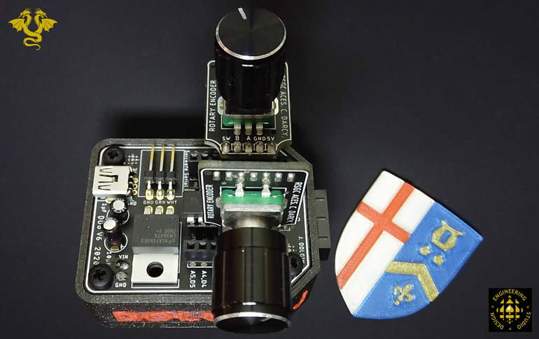
Rotary Encoder. A Rotary Encoder appliance debounced on a breakout board using SMT components is an ideal device to explore Pin Change Interrupts on the DDB. In January 2021 an order for 30 was placed with JLCPCB. The result was successful and will be put to the test in Session 5.2 of COVID-19.2.
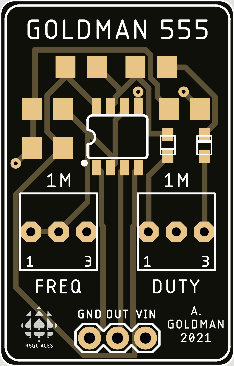
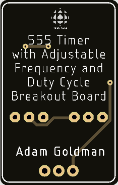
Goldman 555. The third of three boards A. Goldman (ACES '21) produced for his ICS4U Short ISP was an SMT 555 breakout board that offered users square wave output with adjustable frequency and duty cycle controls. A sample run of 5 SMT assembled units were ordered in early January, 2021, and await testing. Update 2022 05 14: Confirmed Adjustable Frequency and Duty Cycle characteristics with Logic Analyzer.
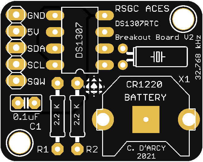
DS1307 RTC Breakout Board. A healthy supply of an RSGC ACES version of Adafruit's original DS1307 RTC THT breakout board was obtained from JLCPCBs in November 2020. A second order of 50 of a modified V3 (shown below) was placed on November 15, 2021. Both are good.
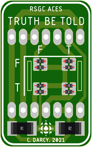
Truth Be Told. This clever addition to our inventory was designed to produce a bicolor truth table (False:Red, True:Green) by inserting the device over a supplied CMOS Logic IC within the family of six silk-screened entries listed on the bottom of the board (below, left). Bicolor LEDs are preferred for V2 if JLCPCB's inventory offers them. A 3D printed diffused hood anchored into the milled vents will produce a better visual. I"ll ask our ACES 3D Print Team for assistance with this.
Breadboard Power Adapter V4. The latest iteration of the ACES Breadboard Power adaptor (affectionately referred to as the PB Machine). The onboard LED supply indicator is useful but is a drain on batteries. With inexpensive SMT assembly services from JLCPCBs, version 4 offers a momentary button to confirm power supply access. A requirement that SMT Assembled PCBs have minimum dimensions of 2cm dictated the enlarged form.
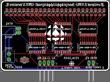
(Appliance) Morland Bargraph SMT Assembled (SPI-compatible). The fourth iteration of the Morland Bargraph was a redesign suitable for JLCPCB's SMT assembly service. Preferred compact resistor networks were not in their inventory so they were broken out into 24 discrete resistor units. 595 shift registers were available, as were the 1206 Blue LEDs. Hand soldering of the RA supply and male headers remain.
A couple of weeks later, five assembled units arrived,
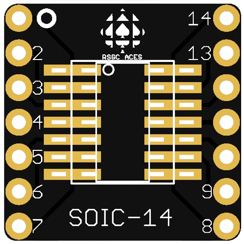
ATtiny84A SMD Trainer. Like its ATtiny85 predecessor, this board is designed to provide Sr. ACES with a smooth transition from THT to SMT components. Designed as a breadboard appliance, the MCU is flashed using the onboard Flat-Flex Cable (FFC) connector and the ACES ISP FFC V2 Adapter.
Attempts to have JLCPCBs produce the original ATtiny85 SMD Trainer continues to be stalled by their perpetual lack of inventory of the ATtiny85 (SOIC-8). They did however have sufficient stock in the ATtiny84A (SOIC-14) so the board was redesigned and an (almost) complete SMT Assembly of 15 units were ordered in August 2020. JLCPCBs SMT Assembly capabilities do not include the FFC Connector, so ACES are required to complete that soldering themselves. Hand soldering of the FFC connector and male headers remain.
A couple of weeks later, here's the assembled result. I had ordered 15 but they admitted they messed up, sent 5 assembled, 10 unassembled pieces and provided a $30 coupon/credit for the next order...
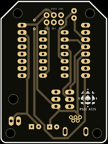
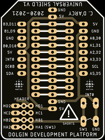
(DDP Shield) Universal Shield V2 (USv2). Dedicated DDP shields (ADC, Intersection, USv1) are tremendously useful for building AVR assembly language knowledge and confidence. Whereas the headers of USv1 allows for the insertion of SIP components, USv2 was developed to allow for DIP devices (bargraphs, ICs, etc.) with a width of 0.3".
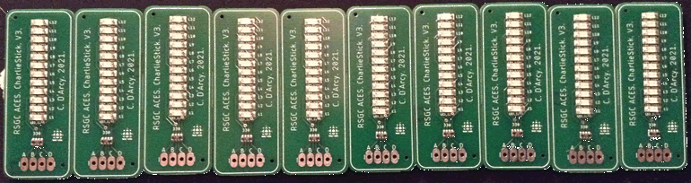
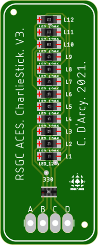
 SMT Assembled CharlieStick. ACES Alumni play a significant role in maintaining our leading edge curriculum. Conversations in the summer of 2020 with E. Peterson (ACES '18, Queen's '22) inspired me to test out JLCPCBs SMT Assembly capabilities. To keep things simple, I adapted our current SMT CharleStick Appliance to fit with their minimum specifications and placed an order for 10. Their rendering appears below, right (click to enlarge). Upon its return, after soldering the right-angled headers, I'll test it out. If it works, I'll distribute them to the 9 2021 Senior ACES. V4. An order for 25 pieces of a modified V3 was placed and received in January 2023.
A couple of weeks later, here's the final order, as delivered,
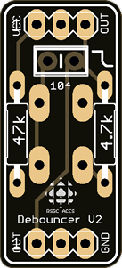
Button Debouncer Breakout Board V2. Mechanical button bounce can be an annoying issue when reading its signal from an MCU GPIO pin. Since bounce is a hardware-generated problem, ACES' preference is to address the problem through hardware. This small breadboard-compatible breakbout board is designed to be a handy timesaver when developing prototypes requiring user button input. Based on this schematic, the PCB can be entirely populated using components from your ACES toolkit. Pin headers are spaced strategically to allow convenient access to the breadboard's power distribution rails. The middle pin of each 3-pin header can be removed prior to soldering. The OUT pins are connected for access to either side of the Nano, for example.
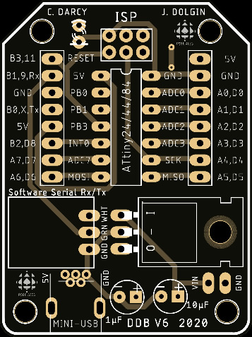
Dolgin Development Board V6 (DDBv6). The opportunity to add Serial IO support to the DDP presented itself when it was determined that Adafruit's USB to TTL Serial cable worked. A redesign of DDBv5 was undertaken in March 2020, yielding the result below. Evidence of DDBv6 and Version 1 of the Universal Shield functioning can be seen in this short clip.
(Training Device) ACES ATtiny85 SMT Trainer. Becoming proficient at developing SMT solutions takes a lot of practice. For this reason, this PCB was developed to condition ACES to the process. Designed as a breadboard shield, the user will use the stencil to apply the solder paste before hand-soldering or baking on its 10 SMT components.
(DDP Shield) Universal Shield V1 (USv1). Dedicated DDP shields (ADC, Intersection) are tremendously useful for building AVR assembly language knowledge and confidence. However, a more versatile, 'universal' shield for the DDP was designed and manufactured in the Spring of 2020 to allow ICS4U students to explore assembly language coding for the ATtiny84's wider feature capabilities and to provide a receptable for SIP devices that can be wired in a more flexible fashion. Once such device is the ACES' SMT Charlieplex Matrix which the DDP alone does not have a convenient footprint for.
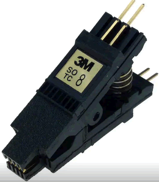
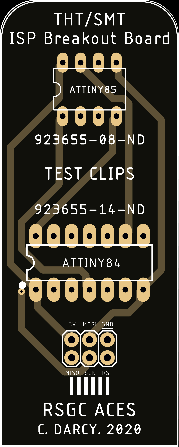
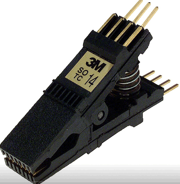
(Breakout Board) SMT Test Clip Breakout Board. In preparation for the 2019/2020 ICS4U Medium ISP requirements for the development of SMT circuitry, an enhancement of our RSGC ACES ISP Breakout Board V2 was deemed convenient. Assembly of the PCB requires a 2x3 male header (connects to Sparkfun's AVR Pocket Programmer) and either female headers or IC Sockets (preferred ?) for the DIP8 (ATtiny85) and DIP14 (ATtiny 84) pads. If all 8 or 14 male-to-female jumper wires connect the PCB to the respective Text Clips users need not necessarily have concern for which 6 are ISP-related.
|
 |
|
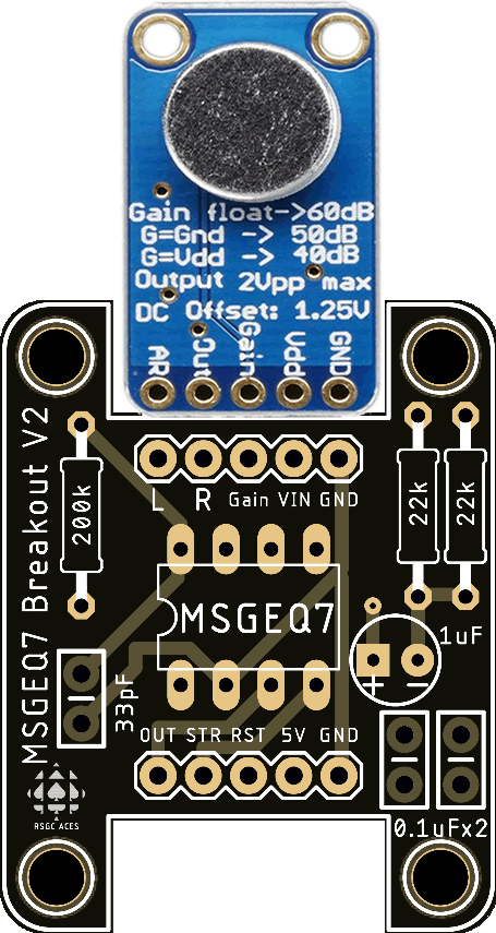
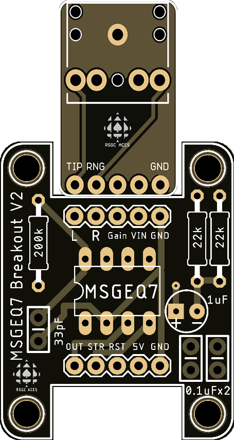
(Breadboard Appliance) Audio Spectrum Docking System. The evolution of RSGC ACES PCB strategies has led to the development of a unique breadboard-based docking system focused on the audio spectrum analysis capabilities of the MSGEQ7. The base station breaks out the pins of the MSGEQ7 in such a manner as to allow ACES' developers to easily dock two input devices (jack & mic) from the top and the control & supply pins from the bottom. Quite convenient.
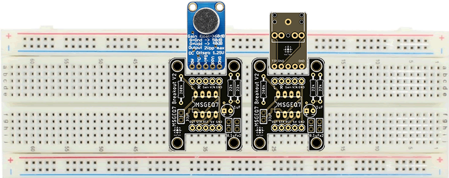
The top header is configured to provide convenient docking with both Adafruit's MAX9814 AGC Microphone and ACES Line In Audio Jack breakout board.
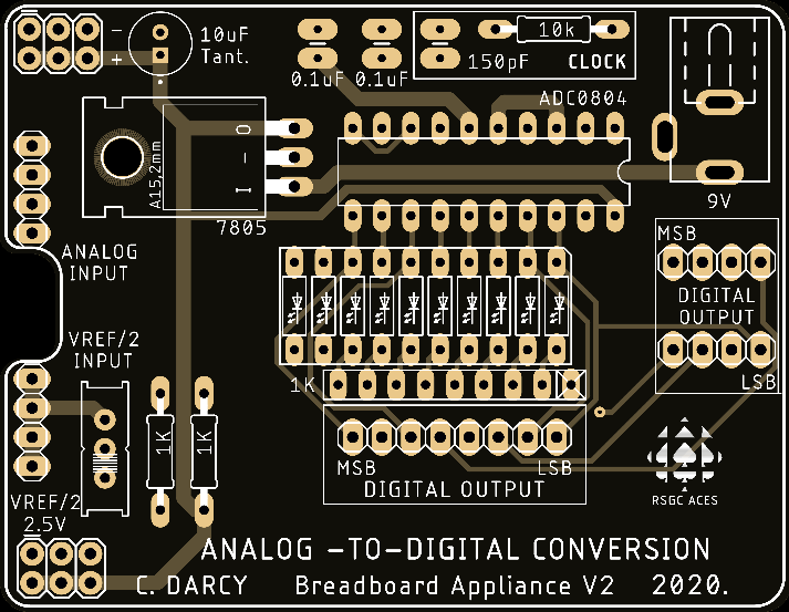
(Breadboard Appliance) Analog-to-Digital Conversion v2. To assist Grade 10s with their transition from analog to digital fundamentals,a PCB in the form of a versatile breadboard appliance has been developed. The appliance offers a 2.1mm jack into which users supply 9VDC. An onboard 7805 regulator puts 5VDC into BOTH pairs of breadboard supply rails thereby eliminating the need for either PB or GB power appliances, for this purpose. Users supply analog voltage levels from 0-5V in the top breadboard hole exposed in the left edge recess of the PCB. Through the use of the onboard ADC0804 IC, free-running analog input voltage levels are converted to digital 8-bit binary values. These values are presented on the onboard LED bargraph. The 8-bit (byte) binary values are also available for additional processing either to the right (as two nibbles), or to a companion breadboard below as a full byte.
For the ADC0804 to perform the conversions it needs a half voltage reference (REF/2), typically this will be 2.5VDC but for increased resolution for narrower ranges, users can supply their own value for REF/2 through the lower hole in the left side recess. A slide switch is provided for user selection with the bottom position selecting the default, onboard 2.5VDC option.
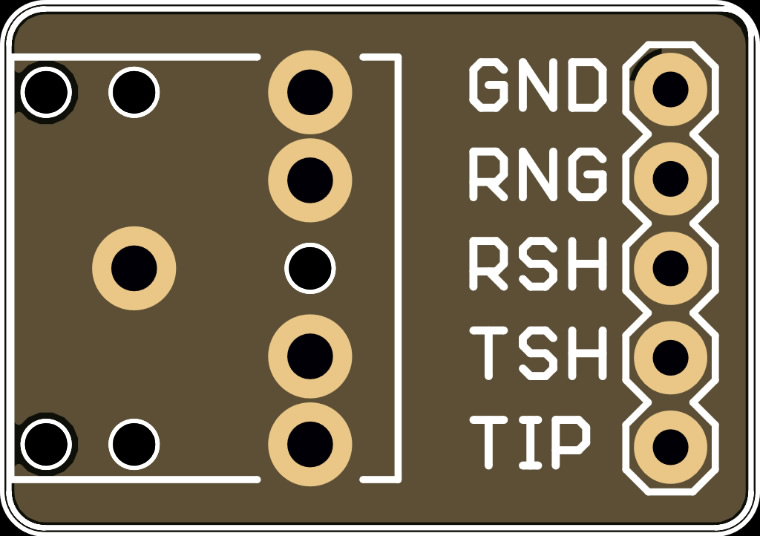
Line In Audio Jack Breakout Board. Although developed in June 2019, the ACES version of the common Line In Audio Jack Breakout Board was not ordered until January 2020, but just in time for use in the ICS3U program. The Ring and Tip Shunt pins support optional interrupt response handling.
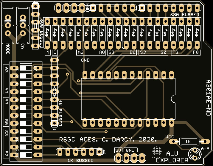
(UNO Shield) ACES CHUMP 74LS181 ALU Explorer. A byproduct of the 2019/2020 ICS4U CHUMP marathon was the development of 74LS181 ALU Explorer Shield for the UNO. The form for the PCB was based on the open source Rev 3 prototyping Shield. A 24 pin ZIF Socket was incorporated into the design to allow for easy manipulation of the increasingly scarce 74LS181 IC. Uses can toggle the bits in the two input operands (A and B) as well as the 4 Select bits, the Mode and Cn bits. Input is echoed on the 20-pin bargraph along with the Function Output bits. The status of the A=B output pin is shown on a separate 3mm LED.
(UNO Shield) ACES CHUMP AT28C16 EEPROM Burner. Another byproduct of the 2019/2020 ICS4U CHUMP marathon was the development of AT28C16 Burner Shield for the UNO. The form for the PCB was based on the open source Rev 3 prototyping Shield. A 24 pin ZIF Socket was incorporated into the design to allow for easy manipulation of the increasingly scarce AT28C16 IC. Additional capabilities of this shield allow for mapping a second set of codes through the use of a PAGE bit (pin 13) and an onboard read back confirmation of burning through the use of a shift register/bargraph tandem.  EEPROM Burner Code
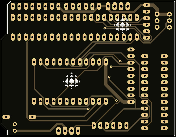
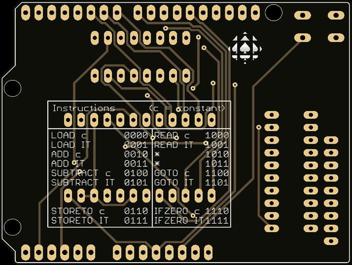
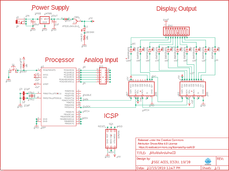
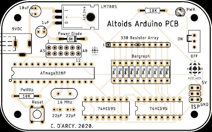
Altoids Arduino VU Meter. In support of the 2019/2020 ICS3U introduction to EAGLE, the decision was made to build on a previous project of theirs that required them to solder their application to Adafruit's generic mint tin PCB and install the assembly in an Altoids tin adapted for required openings. Taking the dimensions from Adafruit's public domain EAGLE design files, an investment of 4 classes prior to Christmas produced a similar-sized custom PCB that future ACES could exploit as a VU Metering device. On receipt of Version 1 of these boards, J. Shibley (ACES '21) offered to solder up one, after which code was developed that confirmed everything worked as expected (shocking for V1).
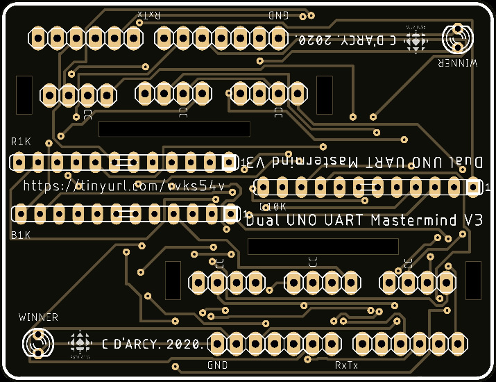
Serial Mastermind V3. Hardware and Software Serial Communication exploiting the AVR's UART capability converge in this UNO R3 PCB appliance developed initially for the 2019/2020 ICS3U ACES. Used in conjunction with the custom ACES library, SerialMastermindV3, two players attempt to expose their opponents secret three-colour code, hidden in behind a custom 3D printed hood courtesy of J. Dolgin (ACES' 20). The winner will be declared by lighting his red Winner LED :). Update: Tested successfully in class on 2020 02 25!
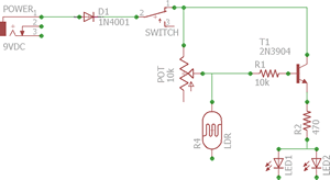
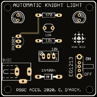
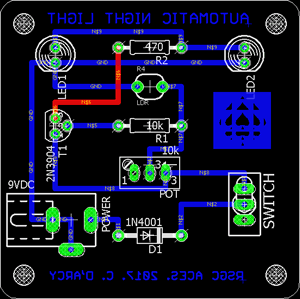
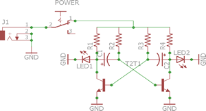
Automatic Knight Light. Modifications to the earlier version of the classic ACES' Night Light included enlargment of many pads for easier soldering by Grade 6 students, replacement of the On/Off switch to a side actuator, linear arrangement of transistor pads and updated silk screening. 2019/2020 Grade 6 students will undertake this project.
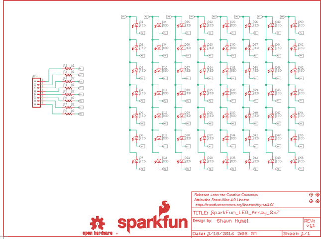
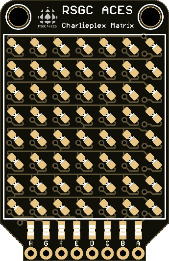
SMT Charlieplex Matrix. An unexpected level of interest by the 2019/2020 ICS4U class in the SMT soldering and coding of the RSGC ACES' (Linear) CharlieStick inspired the adaptation of the open source Sparkfun Charlieplex Matrix. Fearless ACES will use the stencil to apply the solder paste before populating the PCB with 56 0603 LEDs and 8 82Ω fixed resistors and baking the assembly in our Hodgson Reflow Oven. Right angle headers turn this device into an ultraslim Appliance to be used with either the UNO, the Dolgin Development Board, or general breadboard use. At 8×7, this is an ideal board to be used with the MSGEQ7 7-Frequency Audio Spectrum Analyzer IC. For the extremely motivated, can a DDB Shield be far away? Hmmm...could this possibly open the door to my long-anticipated RSGC ACES Desktop Equalizer???
|
|
 |
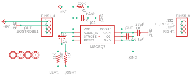
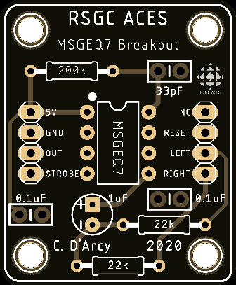
MSGEQ7 Breakout Board. Patterned after the ChronoDot and other such boards, the ACES' MSGEQ7 Breakout board allows users to smoothly incorporate 7-band frequency spectrum analysis into their own projects. Two 4-pin standard pitch headers spaced 0.9" apart, break out MSI's THT DIP-8 MSGEQ7 IC. Four M3 corner holes allow for further mounting stability.
 DES Day Counter/Equalizer. One of the many highlights to emerge from the 2017/2018 ICS4U ACES iteration was the DES Day Counter/Equalizer that hangs proudly to at the front of the DES. This was a terrifc design/electrical collaboration between D. Dadyburjor and E. Peterson. As is often the case, the year ends before the assembly can be locked down tight and polsihed to the point a device can withstand use for ywars after is realization. In the Fall of 2019 the unit underwent much-needed maintenance.
To Be Continued...
NeoPixel Library Reference
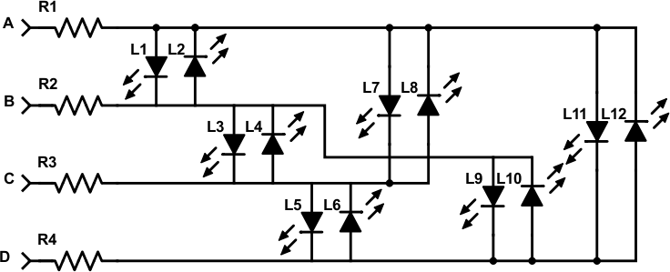
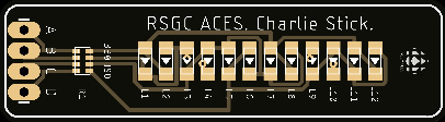
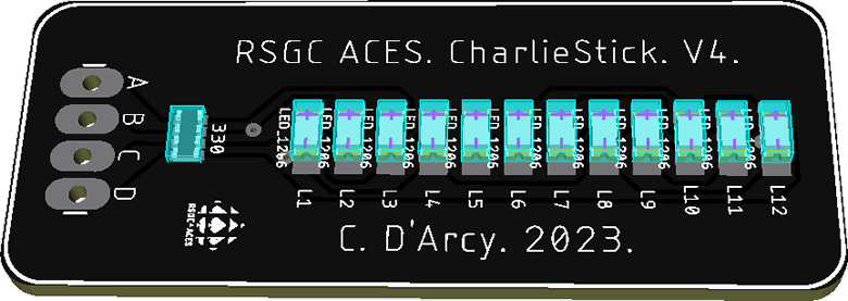
SMT CharlieStick. In preparation for furthering the 2019-2020 ICS4U DDP and SMT soldering experience, Simon Peterson baked a class set of these appliances for both Arduino and Dolgin Development Platform experiences. As can be seen below, four tri-state MCU pins drive 12 LEDs through the application of a strategy known as Charlieplexing. Our 'Charlie Stick' employs an SMT 8-pin Isolated Resistor Array from Digikey. The package is identified as CAY16 and I was able to find a suitable footprint in the EAGLE Resistor_Capacitor Library identified as CAY16-221J4LF although the 330 Ω version was employed. LEDs are 1206 and 4 green, 4 amber, and 4 red were used in the first prototype.
|
 |
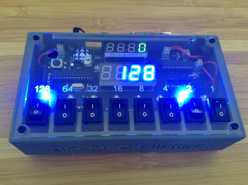
Binary Challenge. As of mid-June 2019 the V1 prototype is functioning. Power and noise inconsistencies require V2, likely ready for testing in late August. Ongoing work on the project can be followed from the development page. 2019 08 30. Thirty units were assembled into KF-A's cases, flashed and the 6 binary challenges tested over the Labour Day weekend (phew!) so they'd be ready for the start of the school year. 2019 09 25. The ICS3U and ICS4U students are enjoying the 5 minutes challenges that are used at the start of class to get them 'into the mood' :)
|
 |
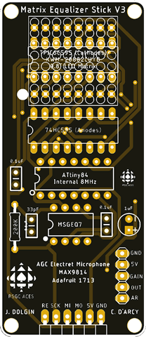
Matrix Equalizer Stick V3. J. Dolgin (ACES '20) replaced the Line In Jack of the Matrix Equalizer Stick (February 2018) with Adafruit's AGC Electret Microphone (Adafruit 1713) as the input device. Further changes to this 5V device, sees the existing obsolete matrix replaced with the more common pin layout compatible with the KWM-20882CUYB 0.8" (20mmx20mm) miniature matrix from Adafruit that is available in a variety of colours. ISP breakout pins have been rearragned in Version 3 for compatibility with V2 of the ACES ISP Breakout Board. The mic, together with the addition of four M3 corner holes for encasement, required a slight increase in the width. Programming of the ATtiny84 can be accomplished with the ACES' ISP breakout board V2 , together with your Sparkfun Pocket Programmer (USBTiny).
|
 |
|
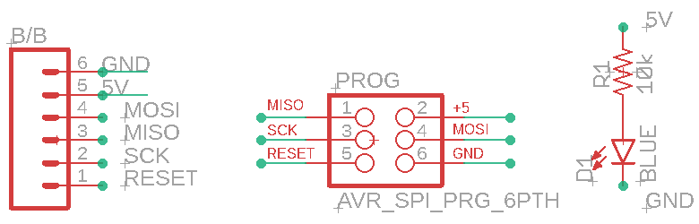
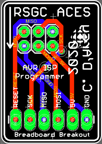
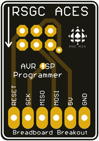
ISP Breakout Board V2. This ISP board is used to flash standalone AVR microcontrollers on a breadboard using your Sparkfun Pocket programmer. An edit of our original ISP Breakout Board has two improvements. The 2×3 input header has been rotated 180° so the ISP cable does not cover the board and the new sequence of signals on the 1×6 output header more closely aligns with the ISP pins of ATmega328P (SCK, MISO, and MOSI). Incidentally, the pins line up perfectly with the ATtiny84-driven Matrix Equalizer Stick V3 (above). For your own ATtiny84-driven device designs, you are strongly urged to follow this ISP breakout sequence.
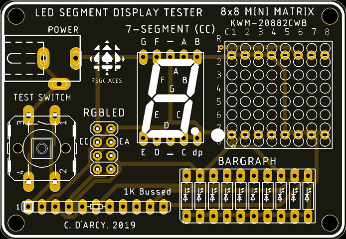
LED Segment Tester v1. An enhancement of the earlier 7-Segment Tester was developed in May 2019 to include a variety of optical display devices used within the ACES program. In addition to the common cathode 7-segment display, users can conform their bargraphs, mini matrices and both common cathode and common anode 4-pin RGBLEDs.
|
ICS3U Competition set for Winter 2020 |
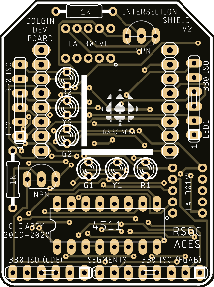
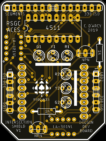
(DDP Shield) Intersection Shield for the Dolgin Development Platform (June 2019). This PCB adds a second entry in our ACES' inventory of shields for the Dolgin Development Board. Maximum use of the ATtiny84's 11 digital pins provides support for two 7-segment countdown displays (one for each direction: B0:B2,A6:A7) and six LEDs (three per direction: A0:A5). 2019 09 30. After soldering up Version 2 and seating it in Version 5 of the Dolgin Development Board everything is functioning as expected.
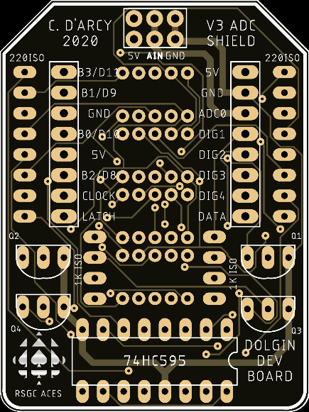
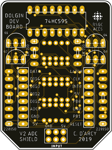
(DDP Shield) Analog to Digital Conversion Shield for the Dolgin Development Platform (May 2019). The first of a number of Appliances and Shields for the Dolgin Development Platform. This Shield exploits the AVR's 10-bit Analog-to-Digital Conversion peripheral. Creative use of the ATtiny84's limited set of 10 digital pins resulted a bank of four small (0.3") 7 segment displays (ROHM: LA-301VL) driven through POV to present the AD conversion to a value from 0-1023.
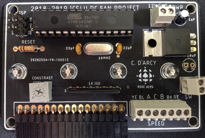
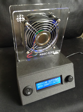
2019 DC Fan Project. (May 2019). At a point in the third term in the Spring of 2019 it was determined that a fitting tribute to the intense AVR Assembly software investigations of the common 4-wire DC cooling fan would be best served by creating an attractive housing for students to enjoy in their dorm rooms in the Fall. K. Fiset-Algarvio, Mr. Elia, and I secretly partnered to develop 10 units of the device that appears below, right. A custom PCB, in-house 3D printed case, and a pair of 2D custom acrylic panels were brought together to create an an attractive device that is driven the very code the students developed together over their final ACES term.
On the last day of classes Mr. Elia was presented with this unexpected device at the very moment a tour of prospective families appeared at our door od the DES, making the moment even more special. Funny how good things somtimes turn out even better than one could have imagined...
Dolgin Development Board V5. (May-Sep 2019). Every year Grade 11 ACES are tasked with imagining and creating a PCB that they think would have faciliated their own skill development had it been available. Out of each year's collection there are typically a few gems that find their way into general use within our program. J. Dolgin (ACES '20) created this small device that breaks out the pins of the AVR ATtiny24/44/84. Pin arrangement reflected compatibility with existing assets, such as the Morland Bargraph v3. The device provides on-board 5V regulation, as well as an ISP header. To complete the package, J. Dolgin designed and printed a custom case enabling side entry Power Jack and an ISP shrouded header.
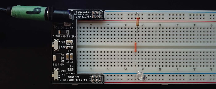
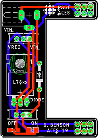
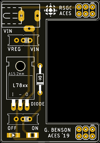
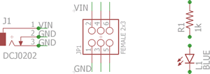
Benson Breadboard Adapter. (April 2019). G. Benson (ACES '19) left his legacy on our program through the implementation of a device that all ACES can benefit from at the very beginning of their prototyping pursuits. A standard 2.1mm power jack accepts power and delivers it to both supply rails on the longer sides of the breadboard, eliminating the need for the hardwiring of the busses. An On/Off switch eliminates the need to disconnect the power from the breadboard while rewiring. Surface mount LED and resistor pads allow for the optional installation of the On/Off indicator. Finally, an onboard 7805 regulator with diode protection allows users to choose between voltage in (VIN) and 5V,
7-Segment Display Tester. (April 2019). The precursor to the LED Segment Tester is this little number that can be used to confirm the status of a common cathode 7-segment display.
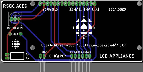
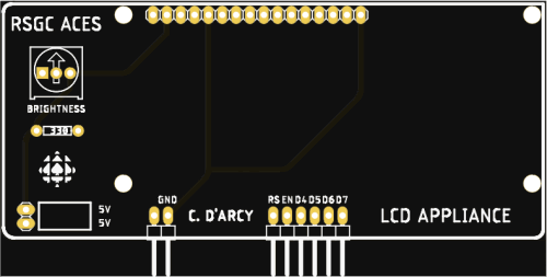
16×2 Character LCD Carrier. (March 2019). Since the wiring of this useful device is a less-than-desirable undertaking, O/C* coverage of Adafruit's ubiquitous 16×2 Character LCD in the Spring of 2019 necessitated the creation of an ACES Appliance. Standard pinheader and hole placement dimensions were readily available online. After a quick solder and attachment to the appliance the LCD panel should be ready for exercise with the software application developed for the demonstration.
|
|
 |
 |
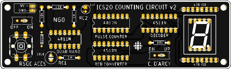
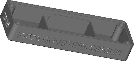
ICS2O Counting Circuit. (March 2019). As dynamic as the ACES curriculum is from year to year, the classic Grade 10 Counting Circuit is a right of passage for ACES. Over the 2019 March Break a custom PCB was designed and manufactured for those ACES that can demonstrate a working breadboard prototype in plenty of time before their DER is due. As he kindly did for the ACES Capacitor Visualizer (see below), J. Dolgin (ACES' '20) graciously designed a custom case for this PCB. The 9V battery resides in an internal well, centered within the case for balance. At 4h a print, only those ACES that successfully solder their PCBs are in line to receive a case to mount their device! Good luck.
Joule Thief V0a. (Planned-March 2019). A tighter design possibility would be to screw a Joule Thief PCB directly to a AA battery holder. Using the dimensions of the holder, a PCB was developed that just might work. We'll see...
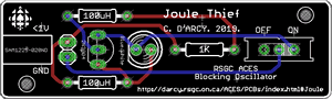
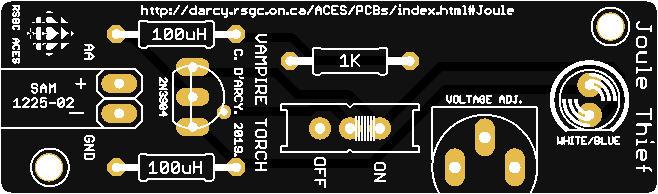
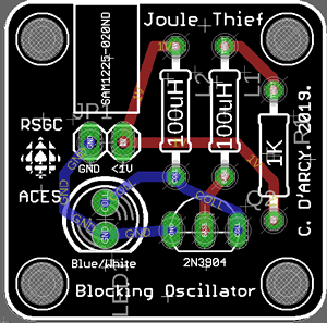
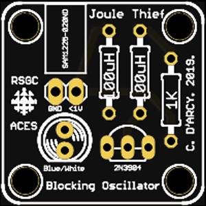
Joule Thief V0. Also known as the Blocking Oscillator, this wonderful little circuit has a charming history and introduces students to the interplay between electricity and magnetism as well as the Persistence of Vision (POV) concept. It is at the heart of the ubiquitous solar garden light in that it can boost the voltage of an all but dead 1.5V AA battery to the point that it can drive the higher voltage (~3V) blue and white LEDs. Prepared for ACES use for the first time in the Spring 2019 ICS2O session, I challenge readers to explore the many variations of this fascinating circuit. This particular minimalist variation uses a pair of 100μH fixed inductors in place of a toroid ring and is described in Wikipedia article. The first ACES project to incorporate this circuit board was assigned in the 2019 Spring session of ICS2O (formerly TEL3M).
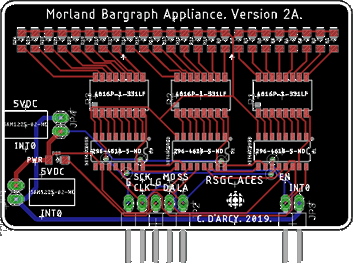
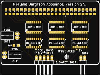
(Appliance) Morland Bargraph SMT V2A (SPI-compatible). SMT V1 worked as expected but but after realization that the AVR's SPI peripheral (on dedicated pins 10-13) can provide the hardware equivalent of the (relatively slower) software shiftOut function a simple, but significant, SMT V1 update was made to accommodate either transfer strategy. I've order 25, just enough for a class set of these that we'll bake in the Hodgson Reflow Oven in early March 2019.
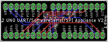
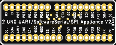
(Appliance) UART/SoftwareSerial/SPI Communication Stick. Wired communication between two Arduinos would make for an interesting gaming experience. An appliance designed to be inserted into two UNOS, avoiding wires altogether would get the game underway faster and leave more time for the competition! This nifty little appliance supports the UNO's hardware UART on pins 0 and 1, Software Serial in pins 8 and 9 and SPI on pins 10-13. A common ground is onboard and stackable female headers allow for other devices to capitalize on the remaining unused pins. I challenge software-leaning ACES to write some games (Tic-Tac Toe, Battleship, MasterMind or whatever...)
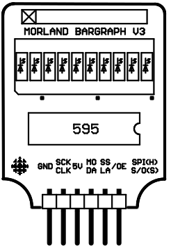
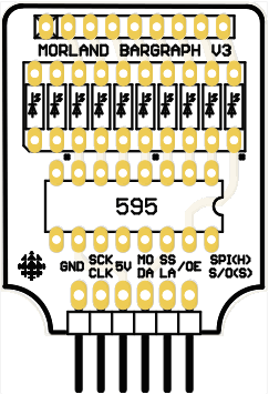
(Appliance) Morland Bargraph V3 (SPI-compatible). Realization that the AVR's SPI peripheral (on dedicated pins 13-10) can provide the hardware equivalence of the (slower) software shiftOut function inspired a simple but significant V1 update to accommodate either strategy. Another subtle redesign consideration was to limit the increased number of pins from 5 to 6, providing the flexibility to implement the device in any of three Arduino (ATmega328p) ports (PORTB, PORTC, or PORTD) to minimize competition for pins with other ACES appliances. Sourcing power from digital pin 12 (MISO is not required for this appliance) is not ideal, but still an esthetically-preferable solution than running a wire to the 5V pin. As 8-LED bargraphs (that match the 595's 8 outputs) are not readily available, the bargraph's two leftmost LEDs (MSBs) remain unconnected. The active 8 LEDs have been changed to right-alignment and small dots added to assist interpretation of the LEDs/bits. The symmetric scalloped corners are cosmetic. White was chosen to enable quick distinction from its V1 counterpart.
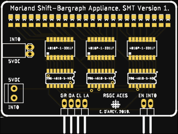
(Appliance) Morland Bargraph SMT Version 1. An SMT version of the essential Morland Bargraph was designed and produced for the 2018/19 ICS4U class. The device worked as expected but a design oversight did not allow for faster hardware SPI transfers. SMT Version 2 will correct this issue to make it SPI-compatible. If you have a functional version of this device, download this code and take it for a test drive.
nRF24L01 Appliance. To prepare for the 2019 ICS3U introduction to radio frequency communication a reworking of an earlier 2017 design by O. Logush was undertaken and converted into a UNO Appliance. The board breaks out the incompatible UNO pin arrangement of the standard nRF24L01 to a wireless (pardon the pun) configuration.
Photophone. One of most remarkable projects from the 2017-2018 Sr. ACES project lineup was E. McAuliffe's (MacGyver-inspired) Photophone. It is both perplexing and inspiring in its simplicity. Ethan took a break from his Engineering studies at McMaster over the holidays to whip up a convenient transmitter and receiver for current ACES to explore and enjoy. Feel free to explore more of Ethan's projects by browsing through his blog.
Development Page
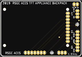
(Appliance) ACES 1.8" TFT Appliance Backpack. In preparation for a 10th Anniversary Reunion with the 2009 Showcase Fair Project in the Spring of 2019 an appliance was designed in January 2019 to mount the 1.8" TFT Backpack from Adafruit. The 2018-2019 ICS4U class will use this device to explore the mathematics of the Mandelbrot and Julia Sets, using fixed point mathematics to accelerate the rendering. (this project may change everything...)
(Appliance) D. Raymond's RTC Clock. D. Raymond's 2018 legacy PCB was a handy little RTC and display that is used to introduce Grade 11s to the I2C communication protocol. A tweaked version in January 2019 of the PCB was converted to an Arduino appliance.
Analog to Digital Converter. A utility board that could be used by Grade 10s to yield a digital display of 10-bit analog voltage conversion levels levels should prove to be quite useful.
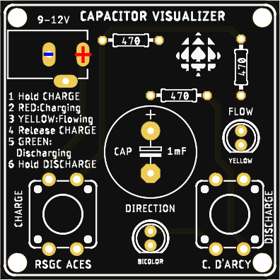
Capacitor Visualizer. A truly marvelous little circuit employing a bicolor LED is of great use in demonstrating the direction of current in a charging and discharging capacitor. The PCB was used the for first time in the Fall of the Grade 10 course and a month later in the Grade 6 Science unit. J. Dolgin (ACES '20) designed and fabricated a set of cases for the Grade 6 implementation to give the prototype a finished appeal. L. Cassano (ACES '22) modified the design in a number of ways.
H. Reed's MatrixMadeEZ. While in Grade 11, inspired by T. Morland's Shift-Bargraph v1, H. Reed (ACES '19) designed a PCB to make short work of coding matrix displays and animations. A year later, J. Dolgin (ACES '20) put the device to great use as a responsive display device for voice-activation, creating a nifty 3D case as well. A short Neil Young clip sealed the deal :) 2022 10 03: V3 created as shown.
Adapter ISP FFC V2. True surface mount devices are flashed through the use of a Flat Flex Cable (FFC) and connector. Either your Pocket AVR Programmer (Arduino IDE) or your ATMEL ICE (Atmel Studio) cables will connect to the 6-pin male ISP header on the board (right). Great care must be taken in designing your EAGLE files to ensure the 6 signals are in the correct arrangement as shown.
Astable Multivibrator v3. Having finished the first batch of 100, replacement order to Dirty PCBs for 300 slightly modified units was placed in April, 2018. Terminal blocks replaced the two previous LED positions to allow for access to the square wave output.
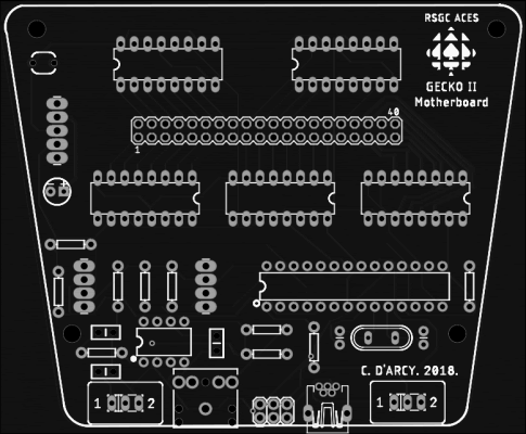
Gecko II. A 2018 upgrade of the classic 2014 model.
| EAGLE Board |
Dirty PCBs (Rendered Image @ Order) |
Soldered & Functioning Device |
|
 |
|
| EAGLE Board |
Dirty PCBs (Rendered Image @ Order) |
Soldered & Functioning Device |
|
 |
|
(Appliance) Matrix Equalizer Stick. DirtyPCBs was called on to manufacture the boards for the Matrix Equalizer Stick PCBs (developed in January 2018) intended for use for the first time in the 2018-2019 Grade 11 course.
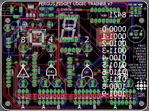
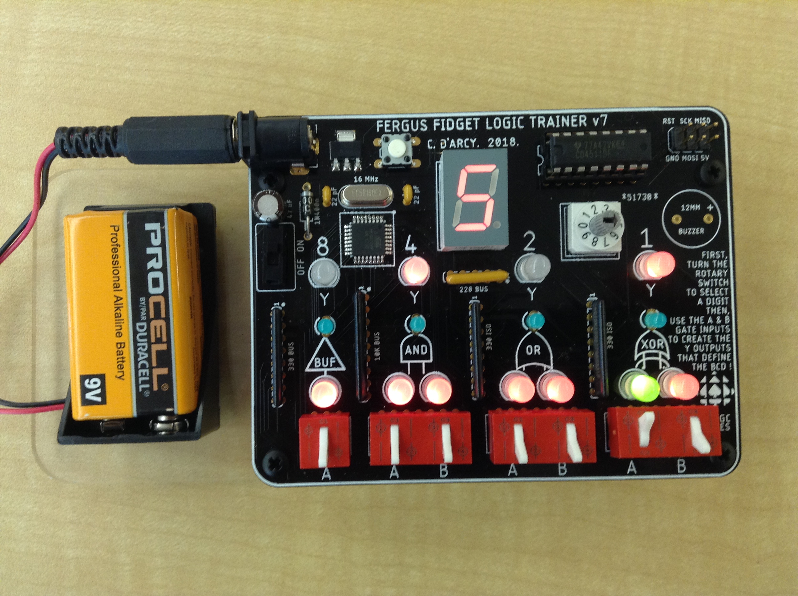
 Grade 5&10. Fergus Fidget Logic Trainer.
A class set of custom designed digital logic training boards intended for use by Grade 5s and 10s hit the ACES round table in the fall of 2018. It took 7 board revisions to get the board to where I wanted it to be. Nick Woollcombe invested dozens of hours soldering SMT components, assembling, and debugging over 30 units. This is a one-of-a-kind RSGC ACES labour of passion, that those who understand, can fully appreciate.
Grade 5&10. Fergus Fidget Logic Trainer.
A class set of custom designed digital logic training boards intended for use by Grade 5s and 10s hit the ACES round table in the fall of 2018. It took 7 board revisions to get the board to where I wanted it to be. Nick Woollcombe invested dozens of hours soldering SMT components, assembling, and debugging over 30 units. This is a one-of-a-kind RSGC ACES labour of passion, that those who understand, can fully appreciate.
Rotary DIP Switch Encoder - Wurth Electronik
Grade 5 BCD Decoder. In preparation for the session with the Grade 5s in November 2017, we set out to develop a device that the students could use to associate binary input with decimal output. E. Peterson arranged to have the boards manufactured through Dirty PCBs.
Breadboard Power Adapter V3. A revision of the earlier DC Jack adapter by P. Bagga in February 2017 included a 1206 surface mount LED and resistor for power indication. Update January 2020: Due to popular demand we've had to replenish our inventory of this essential device. A few minor adjustments justifies referring to this as Version 3. Slight repositioning of the SMT components was made in 2022. I'll call this Version 4.
2022 08 31: Reordered 50 units (V4) )from JLCPCB. Fall 2022: For the first time Grade 10s will solder the DC Jack and 6-position male connection header onto the PCB.
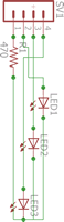
(Appliance) J. Schaffer's Traffic Light. The result of J. Schaffer's introduction to EAGLE in February 2017 yielded this simple, but effective, traffic light circuit board.
(Appliance) T. Morland's Shift Register-Bargraph v1. The result of T. Morland's introduction to EAGLE in February 2017 yielded a circuit board that can be used to develop students' facility in the use of shift registers and as a visualization device for a wide range of sensor projects.
Automatic Night Light. An ACES' version of the Automatic Night Light circuit board was created in February 2017 to support both the Grade 6 and Grade 10 coursework
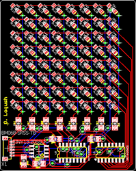
Flex PCB. SMT Matrix. O. Logush (ACES' 18) went all in and designed, ordered, and assembled this 64 LED Matrix flex circuit board. Components were soldered using the DES' Aoyue 968A Hot Air Rework Station. Here's the Flex Matrix in action.
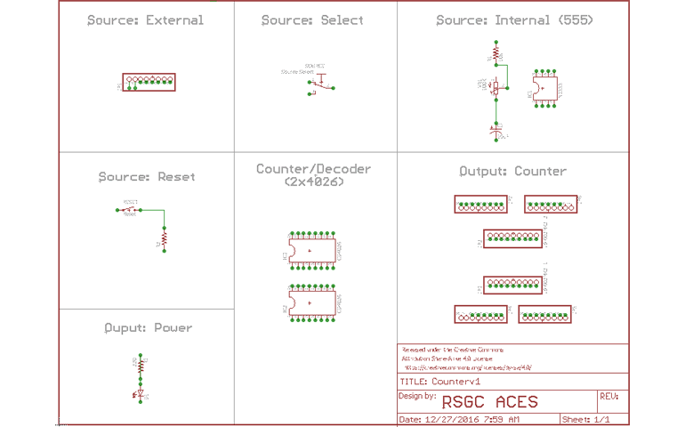
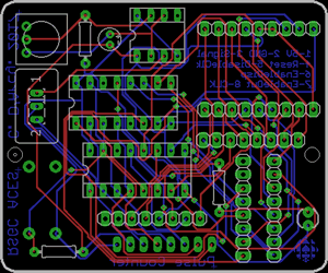
Pulse Counter v1. (Dec-Jan 2016-17) Inspired by a need to count pulses from Timer1 Compare Timer Match Mode in Assembly over the 2016-17 Christmas break, I designed the board below. Two switch-selectable sources (external and on-board 555) provide digital pulses to a pair of 4026 counter/decoders. For numeric output, the LB-602MK2 dual 7-segment display block was employed.
Design Decisions. The precise dimensions (and hole placement) of the Gecko was retained, in case a front plate was desired for the device. Right angle pin headers in the external source will allow the board to stand upright on a breadboard.
Breadboard ATtiny85 ISP. To alleviate the hassle of wiring our earlier ISP breakout board, this device is conveniently-placed over top of the ATtiny85. P. Bagga suggested the use of female stackable header pins to make prototyping even faster. Good call, unfortunately, 4-pin stackable headers were hard to find but, in the end, a slow boat from Taiwan delivered 200 units :)
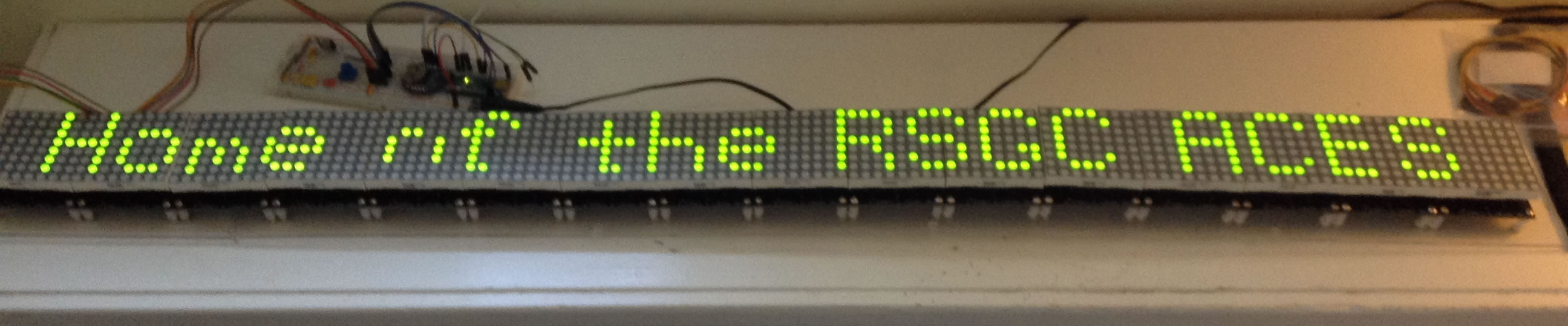
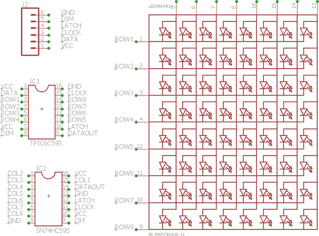
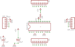
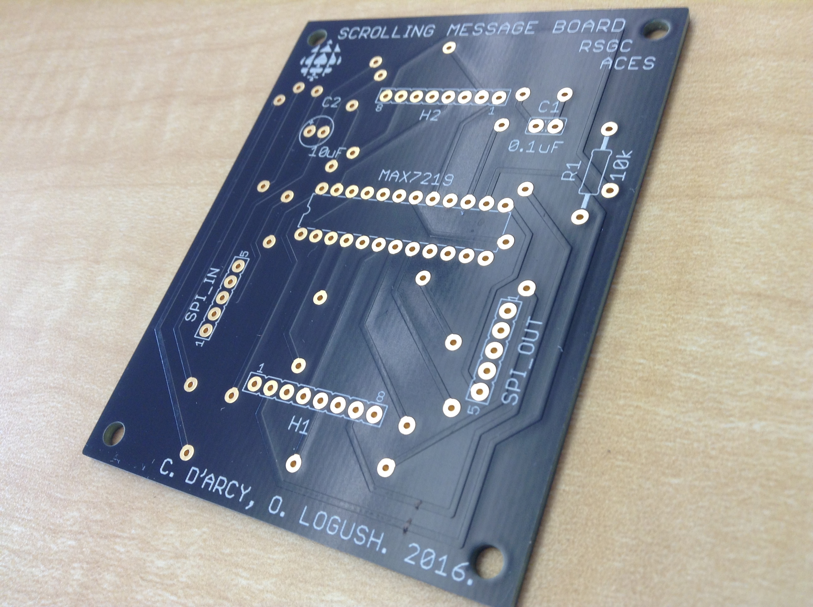
Scrolling Message Board. Every self-respecting DES has a scrolling message board. O. Logush (RSGC '18) agreed to take on the project as a Grade 10 exercise. Three attempts were required to get the module board working the way we liked it (the first two batches are serving their coaster duties well). After a few months in service, the display started developing glitches. Our belief is a build up of charge/EMF so we swapped the MAX7219s for MAX7221s to try to alleviate the problem. We'll see...
Update: 2020 03 15. Over the 2020 March Break (COVID-19-enabled) I took the opportunity to review and refurbish the software with the view to creating a purely hardware SPI display. The result was successful and the display speed is surprisingly fast. Code can be obtained from Scrolling Message Board.
In-System Programmer Breakout Board. This board is used to flash standalone AVR microcontrollers on a breadboard using our Sparkfun Pocket programmer.
Breadboard Power Adapter. Designed by P. Bagga over the Christmas Break 2016/17, these little babies have become quite handy in the DES!
Astable Multivibrator. G. Trusler (RSGC '15) made up a custom batch of these cute little guys for the Fall '14 TEL3Mers. For the Hallowe'en tradition to continue inventory had to be replenished.
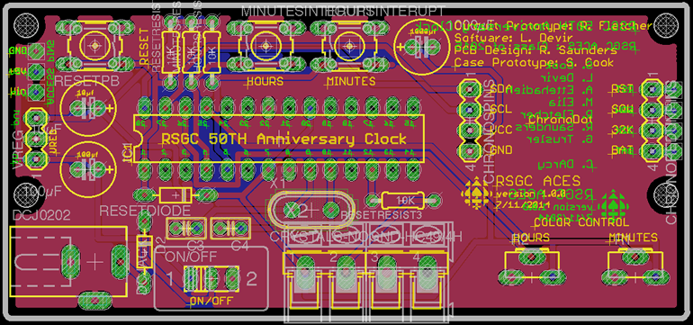
2015 Anniversary Clock
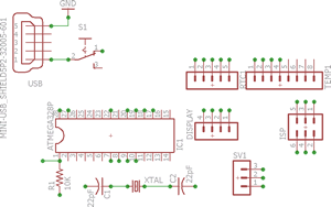
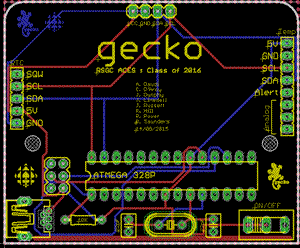
Gecko (Spring 2015). As a legacy project, the 2014-2015 Grade 11 TEI3Mers created this wildly successful clock/calendar. R. Saunders (RSGC '15) did most of the in work whipping the board into shape. Follow the link to learn more about this amazing little device.
*O/C = One Class


