| 2019-2020 ICS3U Engineering Tasks |
![]() ACES' Choice: Raymond RTC Appliance or the Matrix Equalizer Stick. For your second-to-last project of the year, you have 10 days (and 3 work periods) to put together another legacy device. Two aspects of this project that separate it from most others are,
ACES' Choice: Raymond RTC Appliance or the Matrix Equalizer Stick. For your second-to-last project of the year, you have 10 days (and 3 work periods) to put together another legacy device. Two aspects of this project that separate it from most others are,
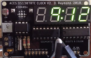
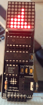
The Raymond RTC Appliance was a legacy PCB concept developed by D. Raymond (ACES '19) for use by ACES as a UNO Appliance based on the DS1307 RTC (kind of like your own personal Gecko) The Matrix Equalizer Stick is a compact PCB designed for use by ACES to confirm their mastery over the MSGEQ7 Spectrum Analyzer and 8x8 Matrix POV coding techniques.
| ACES' Choice | |
|---|---|
| Raymond RTC Appliance (ATmega328p) | Matrix Equalizer Stick (ATtiny84) |
 |
 |
| ACESRTCApplianceRaymondv2.sch ACESRTCApplianceRaymondv2.brd |
MatrixEqualizer.sch MatrixEqualizer.brd |
| RC, ZK, OM, SP, NV, FW, NW | DB, BD, JD, FF, JL, LM, CM, MM, JP, EP, AR, LW |
Task.
 Create EAGLE Projects from the .sch and .brd files I have supplied and look at them carefully. This will give you insight into the software that you (or your team if you are one to rely on others) must develop as shift registers form the backbone of both devices. Furthermore you may wish to modify one (or both - even a combo?) for your own purposes and have PCBs manufactured. The Matrix Equalizer Stick, for example, uses a Line In Jack for your AUX cable where you prefer to adapt it for use with a microphone.

![]() Time-Sensitive Mechanics. (Required Hardware: RTC+Motor+Digital Output)
Time-Sensitive Mechanics. (Required Hardware: RTC+Motor+Digital Output)
Given both the variety and depth of student interest as well as inconsistent access to hardware components, this project provides significant latitude for its final form.
For this second-to-last ICS3U DER Submission (your Long ISP will be your last) you are to imagine a device that places your new mechanical experience (DC Hobby, servo or stepper motors) under time-sensitive control of your DS1307RTC, with digital monitoring of the output on either your LCD or a bank of seven segment displays. A clock is one such device, but that would simply be the first thing that comes to mind. Your imagination will likely lead you well beyond that. Could it be time for your first attempt at animatronics?
![]() DC Motor Control. In the previous DC Motor project we focused exclusively on speed. Since motors are the core of mechanical motion, a reverse mode would not be possible without the ability to control the direction of rotation. The H-bridge transistor arrangement supports a convenient MCU context in which its digital signal can influence the motor's CW or CCW shaft rotation. Both the L293D and SN754410 are pin-compatible H-bridge ICs in your kit that will provide this support. One of these ICs is to be applied in this week's project.
DC Motor Control. In the previous DC Motor project we focused exclusively on speed. Since motors are the core of mechanical motion, a reverse mode would not be possible without the ability to control the direction of rotation. The H-bridge transistor arrangement supports a convenient MCU context in which its digital signal can influence the motor's CW or CCW shaft rotation. Both the L293D and SN754410 are pin-compatible H-bridge ICs in your kit that will provide this support. One of these ICs is to be applied in this week's project.
In this project you are asked to leverage the H-bridge motor concepts and components in such a way as to demonstrate MCU control over your DC motor's speed and direction. Keep in mind that you also have latitude over adding a load to your motor(s) which will require a significant increase in current. This may necessitate the addition of easily customizable heat sinks to dispel excess heat. I caution you that blowing out components due to insufficiently researched and designed circuits will not help you reach your objectives.
Task.
Given the continuing (unusual) conditions we find ourselves in, and the fact that we had a pretty intense project last week, I'm going to pesent a similar format to you, that I did for the 12s this week. You will submit a video DER only that will be a maximum of 3:00 in length, and will demonstrate your comfort and creativity with the application of speed and direction control over your DC Hobby Motor. Many of you appreciate the latitude offered with our projects, especially in this environment in which access to supplies are limited. So, by Sunday night, post an email to handin, under the Subject Line: DC Motor Control, the body of which is simply a link to your video.
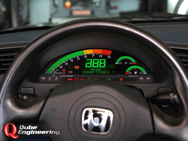
Looking for creativity this week. For example, software-leaning ACES may wish to redeploy their serial (or IR) communication skills in the development of a simple control panel/ dashboard in Processing where users can click on an area to achieve a specific DC motor function. How about a Speedometer? Odometer? Yikes! How inspired can you become?
![]() DC Motor Tachometry. First, some terminology (BC: Before COVID, DC: During COVID, AC: After COVID).
DC Motor Tachometry. First, some terminology (BC: Before COVID, DC: During COVID, AC: After COVID).
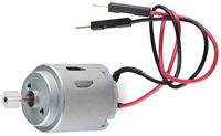
So, for our first official DC project, you are asked to enter the world of mechanics. The characteristics of the hobby motor in your kit are now known to you (research from last class) and it would be a useful undertaking to affirm (or refute) the datasheet's claim that this device can achieve 6600 RPM (±10%) in a no-load context.
I would prefer if the monitoring of the rotation was carried out with your new appreciation for IR sensing and MCU interrupts, however, given the nature of our isolation, alternative strategies may need to be brought to bear. I'll leave that creativity to you.
Important Note. For THIS DC Motor project, you are asked to stick to providing varying voltage levels, of single polarity, to monitor RPM only. You are not to introduce dual polarity features to affect the direction of the spin. We'll get to that next week. Credit will be assigned based on simple, creative straightforward use of the components in your kit (and software assets any ACES can acquire for free) and withheld for the use deluxe components that you may have lying around, but others do not. Explore the concept through fundamentals :)
Hardware Tasks
 Using the assets available to you, creatively mount your motor securely (vibrations will likely affect performance) so that the encoder (or some other minimal indicator you design and create (cardboard and a hole punch might suffice)) attached to the shaft can be sensed at least once per rotation. Recall that those with access to a 3D printer can use one or more of Joseph's offerings (available for download from our course page) or from Thingiverse, found under Optical_Encoder.
Software Tasks
RISING, FALLING, or CHANGE modes of the signal are employed. By way of consideration, use of Joseph's 8-tooth encoder would result in 8 interrupts per rotation for both RISING and FALLING, but 16 interrupts per rotation for CHANGE mode.MeasuringRPM.ino is provided for you as a potential starting point.Additional Considerations
At the outset of our ACES introduction to mechanics, it is highly informative to remember how our investigations lend conceptual and physical support to your study of mathematics and physics concepts. With this project we enter the world of Kinematics, the 'geometry of motion' as it is more commonly referred to as. Motion can be readily explored and analyzed in one, two, or three dimensions (ie. linear, planar, or spatial). There is no urgency to direct you to web references on this topic as I would prefer you to simply reflect on where you think this project, with its implications and applications, fits within the dimensional domains mentioned in the previous sentence.
Big Mouth Billy Bass
Just before the time of your birth, at the turn of the century, the world was hit with an animatronic tsunami in the form of Big Mouth Billy Bass. As if one was not nuisance enough, entire schools (?) of these mechanical poisson were assembled and mounted in homes and businesses like the image to the right of one in a (fish & chips?) restaurant.
Although perhaps too late for this year's Long ISP proposal, if you find yourself drawn to both mechanical and audio technologies, consider putting an animatronic ISP on the shelf for the future.
Finally, as if out of a Stephen King novel, check out this ![]() Motion-Sensed Billy Bass Wall.
Motion-Sensed Billy Bass Wall.
Yikes...
![]() Legacy PCB/Appliance. ACES' Alumni continue to contribute to our program through their former achievements. PB machines, Schaffer Traffic Lights, Morland Bargraphs, Reed MatrixMadeEZs, Logush nRFBreakout, and Raymond RTCs were all straightforward but brilliantly conceived devices that are instrumental in support of our current learning. Take a look through our online archive of ACES PCBs for inspiration.
Legacy PCB/Appliance. ACES' Alumni continue to contribute to our program through their former achievements. PB machines, Schaffer Traffic Lights, Morland Bargraphs, Reed MatrixMadeEZs, Logush nRFBreakout, and Raymond RTCs were all straightforward but brilliantly conceived devices that are instrumental in support of our current learning. Take a look through our online archive of ACES PCBs for inspiration.
To further strengthen your printed circuit board design skills and to give you an opportunity to leave your mark on RSGC's ACES program, you are tasked with the opportunity and challenge of imagining and designing a board that YOU feel would have made YOUR study of electronics a richer (and more time-efficient) experience. The best projects are simple, replace a single task you do over and over, and can be put together with a few handy parts. For my part I have created and continue to maintain a library of common THT parts we use in the DES all the time. Download the library ACES_THT.lbr and use it in your projects.
A few notable considerations to inspire your own creation in include the following,
Tasks
Part 1. Due Wednesday January 8 @ START of class
 You've thought deeply about a simple PCB/Appliance that would have made a previous project you undertook either easier, or richer.
Part 2. Due Saturday January 11.
Part 3. Due Saturday February 1
I will, hopefully, take one or more of these creations, adapt them for use in next year's courses, and secure your legacy in the process!
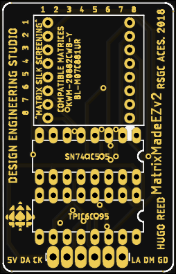
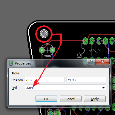
![]() Project 2.5. MatrixMadeEZ. For his PCB project in Grade 11, Hugo Reed (ACES '19, Queen's '23) imagined, designed, and developed a handy PCB that future Grade 11s could exploit to hone their LED matrix animation skills. We're going to incorporate Hugo's terrific little device into a creative implementation due on Saturday December 14.
Project 2.5. MatrixMadeEZ. For his PCB project in Grade 11, Hugo Reed (ACES '19, Queen's '23) imagined, designed, and developed a handy PCB that future Grade 11s could exploit to hone their LED matrix animation skills. We're going to incorporate Hugo's terrific little device into a creative implementation due on Saturday December 14.
Parts List for Hugo's MatrixMadeEZ PCB (all can be found in your toolkit),
The header will enable your device to be mounted vertically in your breadboard, driven by your official (or breadboard) Arduino, or even an ATtiny84 or ATtiny85. Note. this is NOT an appliance for the UNO as there is no 5V access on the digital pin side.
Task.
 Many of you are hardware-driven, some are software-inspired and still more of you enjoy the design opportunities this course affords. While covering off ALL THREE domains to some extent (hardware, software, and design), feel free to push your preference for one (or two) to the limit in developing a device capable of presenting a compelling animation on your MatrixMadeEZ.
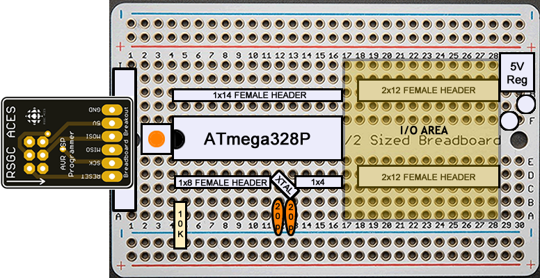
![]() Project 2.4. Altoids Arduino. (An ACES first) The goal of any embedded system designer is to engineer an in-system programmable (ISP) and functioning microcontroller, housed in a physical and electronically-stable case. This project gives you your first attempt at creating such a device (and sets your design ideas in motion for our custom PCB and CAD cases in the second and third terms...)
Project 2.4. Altoids Arduino. (An ACES first) The goal of any embedded system designer is to engineer an in-system programmable (ISP) and functioning microcontroller, housed in a physical and electronically-stable case. This project gives you your first attempt at creating such a device (and sets your design ideas in motion for our custom PCB and CAD cases in the second and third terms...)
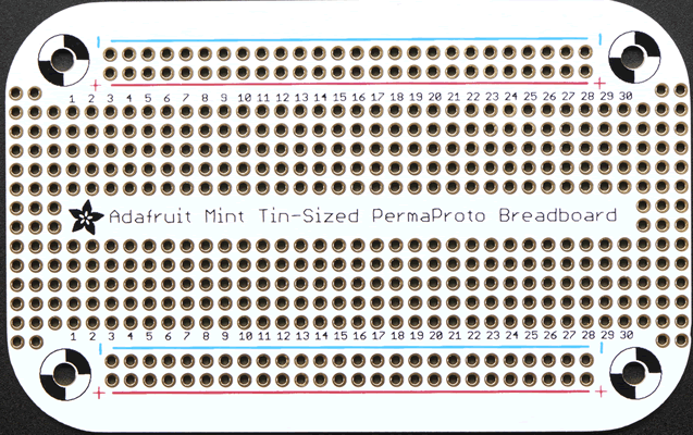
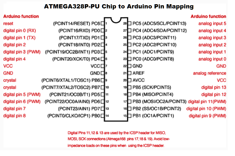
The graphic to the right is my simplified layout for a next-to-minimal, standalone Arduino-like device on a perma-proto half board. At the top left you'll see the RSGC ACES ISP breakout board you were supplied with that will be your means to program your in-place ATmega328P MCU (the MCU will sit in a supplied IC socket so you can remove your MCU as required). In the top right, you'll see the 5V regulation section where you may choose to provide a 7V power source or (slightly) higher as a substitute for 5V power supplied through your ISP BoB by way of your Sparkfun Pocket AVR Programmer.
Most of the additional requirements and wiring are left to you to determine from the direction and knowledge provided in class.
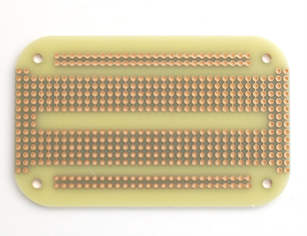
| Adafruit's Mint Tin-Sized Perma-proto Board (front) | Adafruit's Mint Tin-Sized Perma-proto Board (back) |
|---|---|
 |
 |
Task 2.4.1. Breadboard ATmega328P
| Supplemental Parts List for 2.4.1 | |
|---|---|
| # | Description |
| 1 | RSGC ACES ISP Breakout v2 |
| 1 | 2x3 Male Header Pins (ISP) |
| 1 | ATmega328P MCU DIP28 |
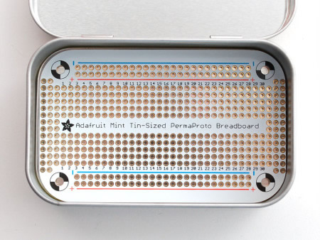
| Altoids Tin (student supplied) | Adafruit's Mint Tin-Sized Perma-proto Board in Place |
|---|---|
 |
 |
| Supplemental Parts List for 2.4.2 | |
|---|---|
| # | Description |
| 1 | Adafruit Mint Tin-Sized Perma-proto PCB |
| 1 | Altoids Mint Tin (student-supplied) |
| ? | 1x4 Female Header Socket |
| ? | 1x8 Female Header Socket |
| ? | 1x14 Female Header Socket | ? | 2x12 Female Header Socket |
| 1 | 28-pin kinked DIP Socket |
| 1 | Power Jack 2.1mm x 5.5mm |
| 1 | cool mystery part for the successful |
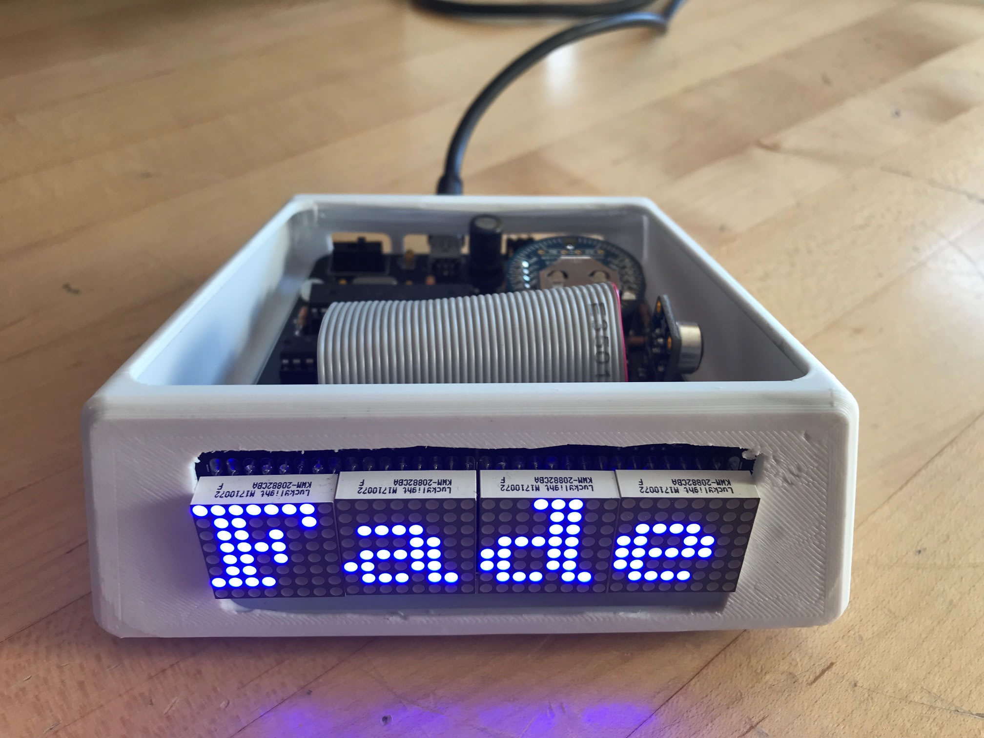
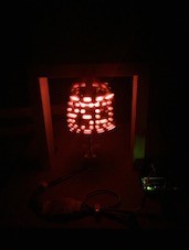
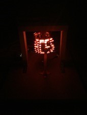
![]() Project 2.3. PoV Word. (Reference: AVR Foundations: pp.34-39). It's strange to think that our eyes perceive much of the LED lighting around us to be uniformly ON, when they are actually OFF as much as half the time (maybe this is one of the reasons LED lighting is so cost-effective?). Point your phone's camera at the digital clock in the DES and see the result when this oscillation interferes with your device. K. Fiset-Algarvio created a remarkable Persistence of Vision Globe in Grade 11 for his ISP. Unfortunately, the video is no longer available as he uploaded it to YouTube using his RSGC account, which is no longer available:( I did manage to retrieve two photos from his DER as evidence of the dramatic result.
Project 2.3. PoV Word. (Reference: AVR Foundations: pp.34-39). It's strange to think that our eyes perceive much of the LED lighting around us to be uniformly ON, when they are actually OFF as much as half the time (maybe this is one of the reasons LED lighting is so cost-effective?). Point your phone's camera at the digital clock in the DES and see the result when this oscillation interferes with your device. K. Fiset-Algarvio created a remarkable Persistence of Vision Globe in Grade 11 for his ISP. Unfortunately, the video is no longer available as he uploaded it to YouTube using his RSGC account, which is no longer available:( I did manage to retrieve two photos from his DER as evidence of the dramatic result.
 |
 |
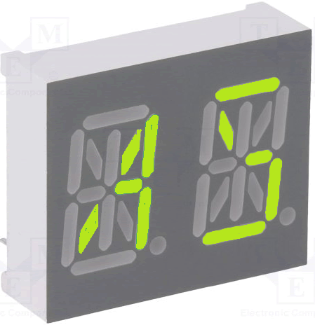
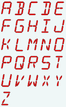
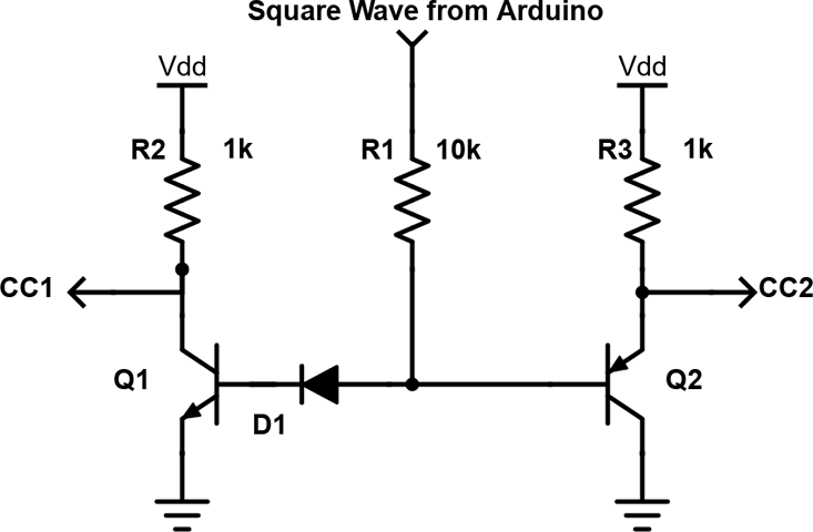
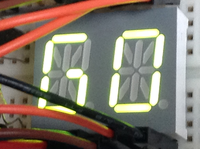
You have been lent an LTP-3784G (a green, common cathode, dual-digit 14-segment alphanumeric display). An image of the device appears below, left, in which I have coloured a few segments to simulate a 'possible' depiction of the two-letter word AS. Click on the previous link to review the datasheet for this device and familiarize yourself with its pin layout. This component is to be driven by two SN74HC595 shift registers* and a pair of transistors (one NPN and one PNP) under control of a single square wave (bottom, right), in a Persistence of Vision scheme. See Fritzing image at end.
*Although the ATmega328p has enough pins to complete this task without using shift registers, you are required to do so, for practice.
 |
 |
 |
Task.
Advice (trust Mr. D's experience)
 This is a CHALLENGING project. Do NOT doubt yourself, you are all talented enough to complete it. Success follows those who simply devise a SMART plan and have the DISCIPLINE to execute it.
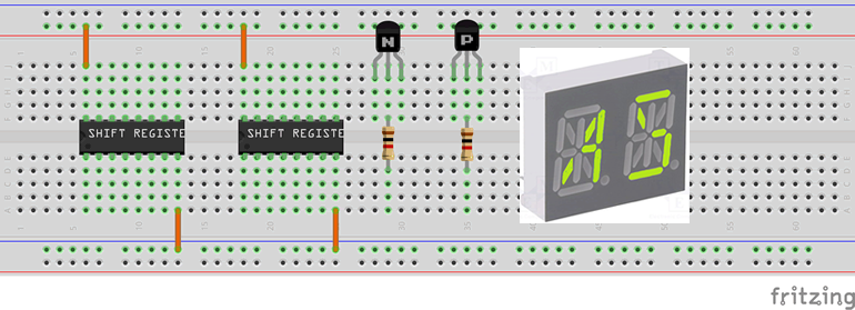
![]() Project 2.2. Binary Button Echo. Your in-class experience with our new Binary Challenge Device has already prompted a number of students to suggest design improvements. Your second project capitalizes on your expressed interest and curiosity with a view to possibly inspiring someone to consider taking on the development a prototype for an improved training device as an ISP.
Project 2.2. Binary Button Echo. Your in-class experience with our new Binary Challenge Device has already prompted a number of students to suggest design improvements. Your second project capitalizes on your expressed interest and curiosity with a view to possibly inspiring someone to consider taking on the development a prototype for an improved training device as an ISP.
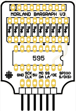
When Tim Morland (ACES '18, Queen's Eng '22) was in Grade 11, he designed version 1 of the adjacent Arduino Appliance (ACES refer to an 'appliance' as a PCB specially designed to insert directly into the female headers rather requiring unstable breadboard and wire connections) consisting primarily of a SN74HC(T)595 Shift Register and a bargraph. Your toolkit contains the SN74HC595 IC, a 16-pin IC Socket, right angle snappable male headers, and a 10-LED blue bargraph. The remaining parts, a 330 Ω 9-pin (8-resistor) bussed resistor network and Tim's PCB, will be provided to you. Only the 8 least significant LEDs are accessible. Tim's appliance will function as the output device for this project.
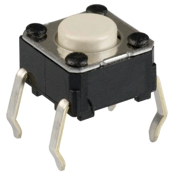
For input, you are to use 8 separate momentary tactile button/switches (you have a bag of 20 left over from your Grade 10 toolkit).
Task. Your task is to develop an Arduino-based prototype that has your software continuously (and correctly) monitor the state of the eight input buttons and echoing their states on your Morland Bargraph. They key to this project is how you acquire and assemble the button data input for presentation to the Shift Register output. Note: There are so many ways to do this, it is unlikely that any two ACES will accomplish this the same way...
Advice. Only those students that start EARLY on this project, thereby leaving themselves sufficient time to make mistakes, explore unique strategies or even head down to Creatron for a part or two they think might make a creative difference, will earn the deep satisfaction of personal triumph. Those that don't, won't be able to resist the temptation to cast an eye on what others are doing, thereby hindering their own growth and development.
A final word. Given that collaboration to limited extent is permitted and there are no tests to filter out who has actually mastered the skills, it typically falls to the creative and marginal differences in your prototype and DER content to determine the awarded credit.
 |
 |
![]() First, make the following edits to your DER,
First, make the following edits to your DER,
 Project 2.1. Traffic Light. Since many of you will be pursuing your driver's license in the near future, the focus of this first project is the careful soldering and QUALITY programming of a standard traffic light. When Jasper Schaffer (ACES '18, Queen's '22) was in his TEI3M year, he designed the handy little PCB pictured to the right that we'll exploit to start our year off. For the assembly aspect of this project you will solder one each of a green, yellow, and red 10mm LED and a four-pin right-angle header from your toolkit onto the Schaffer Traffic Light PCB you have been provided with. Take care as there are NO replacement parts. The male header pins allow your device to be inserted directly into adjacent female port pins on your Arduino (eliminating the need to use a breadboard and hookup wires). Be sure to document your soldering of the device through video acquisition that you can include in your report. For the testing aspect, you will include media as well as a well-planned sketch based on our discussions in class. The fully documented sketch should cycle through the LEDs continuously with the green and red remaining on for four times the duration of the yellow (amber) LED.
In your report, you are include the Purpose, Reference, Procedure, Code, Media, and Reflection subsections in Heading 2 style. A full Parts Table, with background shading consistent with your Grade 10 theme and width of 3" and should appear right-aligned within the Procedure section. Finally, ensure that no content is allowed to spill into any of the four page margins.