 Microchip's upgrade of the classic AVR line of ATtiny MCUs deserves some attention, from an open source point of view. These MCUs offer greater functionality over their predecessors, are cheaper, and are highly suitable for smaller embedded applications. On the other hand, they are not available in through hole packages (THT) requiring more prototyping effort for ACES and Hobbyists.
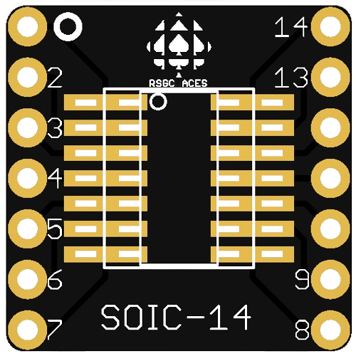
So, after slight modifications to Adafruit's SOIC-14/TSSOP SMT Breakout Board, 100 RSGC ACES boards were ordered in March 2024. A further 50 were ordered with ATtiny414's SMTs soldered onto them for immediate testing.
The next challenge is how to program these MCUs. Given their minimal pin count Microchip abandoned the 6-pin ICSP standard in favour of a new proprietary 1-pin strategy known as Unified Program and Debug Interface (UPDI). This is a somewhat straightforward solution if Atmel/Microchip Studio is your IDE but ACES do not have access to this application. So, it was left to the open source community to come up with a DIY UPDI programmer that could be incorporated into the Arduino IDE. Thanks to Spence Konde (aka Dr. Azzy) we have board cores for this suite of MCUs. Following the UDPI programmer design suggested by a number of bloggers, I have designed and ordered our own RSGC ACES UDPI programmer as of March 2024.
Three UPDI Programming Options
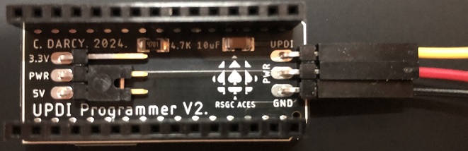
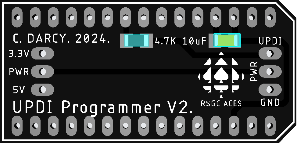 1. ACES' UPDI 'Shoe'. Pictured to the right is JLC's representation of what I've dubbed our ACES' UPDI Shoe. Below is a photo of the PCB assembled upon receipt. Additional through hole parts include two 15-pin female headers, two 3-pin right angle male headers and a two-pin shunt connector (selects between 3.3V and 5V).
This short guide explains how to use it as a UPDI programmer (with your Arduino Nano) to flash an ATtiny414 on our ACES SOIC-14 Breakout Board.
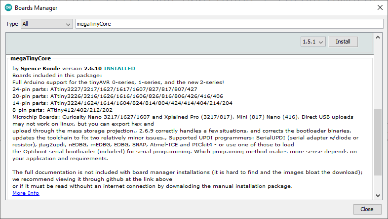
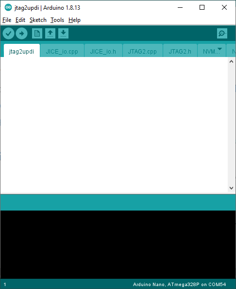
- Prepare your Arduino IDE by first launching the Board Manager and installing Spence Konde's megaTinyCore
- Download Konde's AVR-Guidance Zip file and create an Arduino sketch from his jtag2updi code. Overlook the empty main sketch and upload this code to your Nano BEFORE you place your Nano in the ACES' UPDI Shoe.
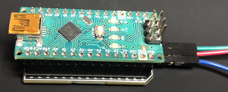
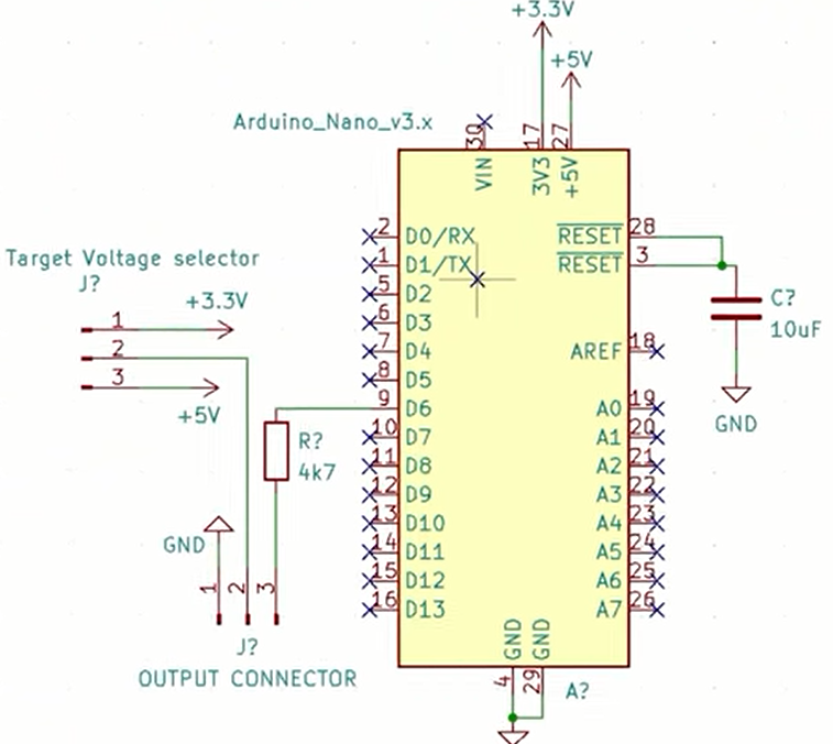
- Place your Nano in the ACES UPDI Shoe as shown below. It was designed to be an inexpensive alternative to commercial options. Our UPDI Shoe has the SMT 4.7 kΩ fixed resistor and 10 μF (Reset) capacitor onboard. The female/male wires are as follows (Green:UPDI, Red:VCC; Blue:Ground). Wire the ACES' UPDI Shoe to the prototype as shown below.
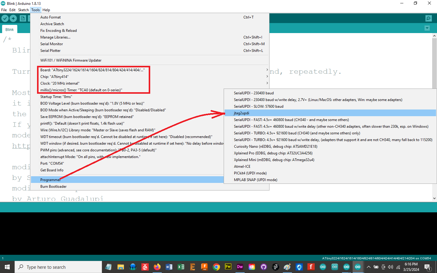
- From the Tools menu make the following selections.
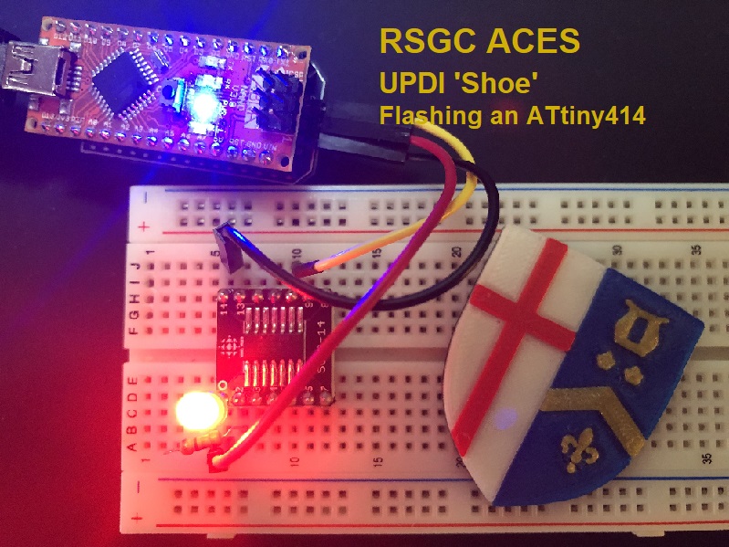
- Open the Blink sketch and change instances of LED_BUILTIN to 0. Under Sketch, select Upload Using Programmer. The LED should now be flashing.
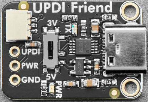
2. UPDI Friend
For an alternative programmer, I ordered two of Adafruit's USB to Serial UPDI Friend from ABRA. Worked like a charm programming an ATtiny414. Price and availability are small concerns.
References
C. D'Arcy. March 2024.