ACES prefer to make their own tools. At the end of his second course, S. Appleyard (ACES '23) applied his time, hardware skills, and design talent over the summer of 2022 to developing an improved LED Tester (functionality and cost) for inclusion in each of the toolkits of the incoming 2022/2023 Grade 10 ACES. After multiple design iterations and overcoming numerous supply chain challenges, his devices were complete and ready for September 2022 ICS2O distribution. Follow the instructions below to successfully assemble and test your Appleyard LED Tester.
![]() Please follow the instructions carefully and with caution as there are no replacement parts.
Please follow the instructions carefully and with caution as there are no replacement parts.
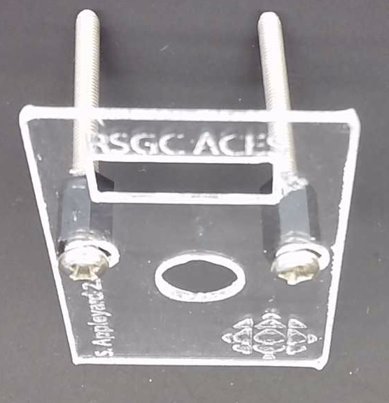 1. Custom acrylic top plate, steel 30 mm M3 bolts, and female hex spacers. After confirming the orientation of the engraving on the acrylic slip the M3 bolts through it. Hand-thead the female hex spacers onto the bolts as shown. stopping within 1-2mm of the acrylic
 ![]() Tightening them all the way at this stage will likely result in cracked acrylic during later assembly.
Tightening them all the way at this stage will likely result in cracked acrylic during later assembly.
Click on the image to enlarge.
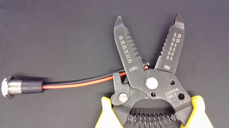
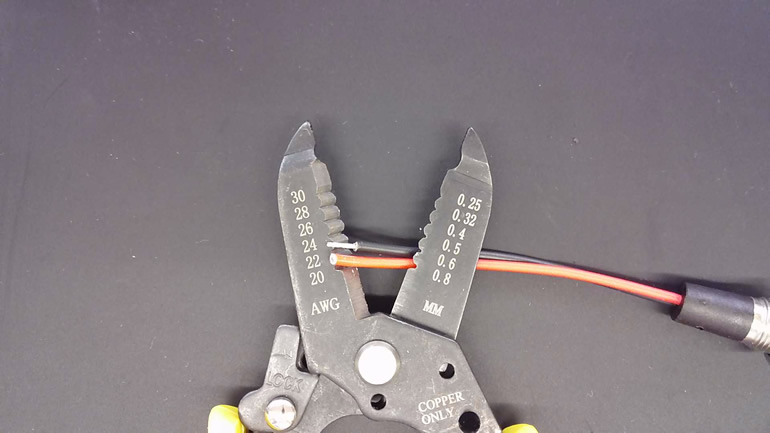
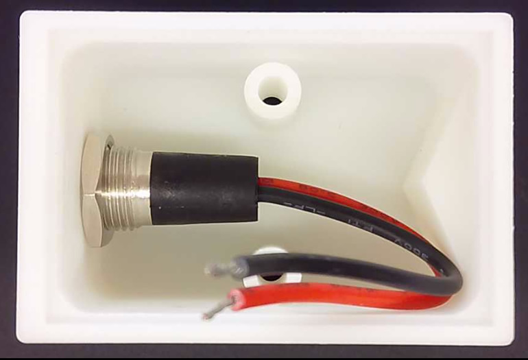
2. 3D Printed Case, 2.1 mm Barrel Jack. Use your wire strippers for two tasks (cutting and stripping). First, cut the length of the leads to approximately 6 cm as shown below, left. Next, trim off 0.5 cm of sheathing from both the RED and BLACK leads, exposing the stranded wire core (below, middle). Twist each one separately. Remove the collar nut from the barrel jack, insert the jack into the 3D case and secure the jack to the case (below, right) Again, hand tighten only to avoid cracking the case. Click on each image to enlarge.
| Cut Leads | Trim Leads | Secured Barrel Jack |
|---|---|---|
 |
 |
 |
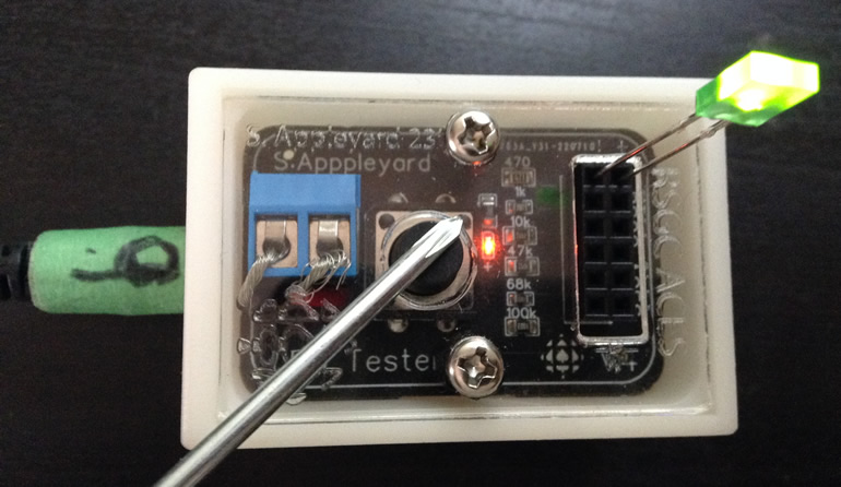
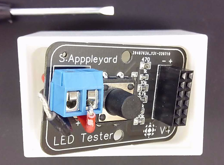 3. Appleyard LED Tester PCB, Slot Screwdriver. Using the slot screwdriver from your kit, feed the leads of the wires through the holes in the PCB (red + and black -) and secure them to the blue terminal block as shown.
Click on the image to enlarge.
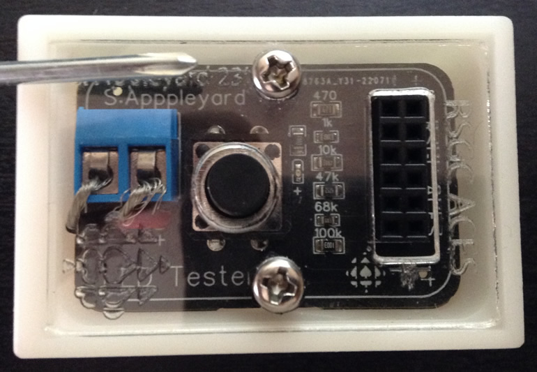 4. Assembly from Step 1, Nylon M3 Hex Nuts, Phillips Screwdriver. Position the acrylic assembly from Stage 1, PCB, and as shown below. Insert the M3 nuts into the pockets are the bottom of the case and gently screw the entire component suite together. Do NOT overtighten.
Click on the image to enlarge.
5. Power Source. Provide a 5-9V power source for the barrel jack and test an LED, ensuring the correct polarity. Test various positions for varying current/brightness.