| ACES LED Tester |
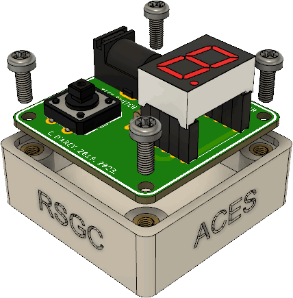
 A device that can quickly confirm whether an LED is still functional is a useful asset to have on your bench. Retail LED testers are readily available but ACES prefer to make their own tools. In doing so, custom features and modifications can be added. In the device described below, not only can single LEDs be tested but, later in the course, you'll have need to test your common cathode (CC) 7-segment display units. The female header pins allows for easy insertion and testing of this display unit.
Familiarize yourself with the components outlined below and listen carefully to the soldering instructions provided in class to successfully assemble and confirm your ACES LED Tester.
![]() Again, follow the instructions carefully and with caution as there are no replacement parts
Again, follow the instructions carefully and with caution as there are no replacement parts
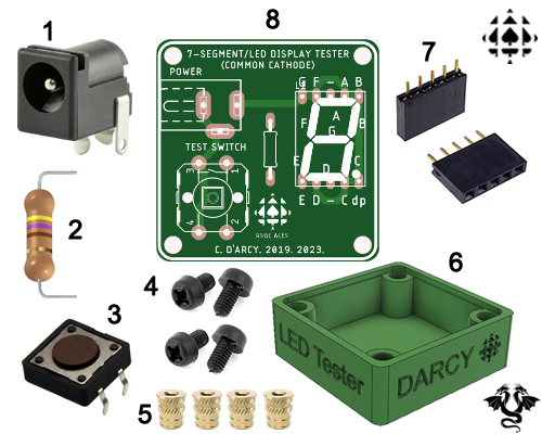
1. Parts. Below is an image of the parts required to assemble your ACES LED Tester. Click on the image to enlarge. Below, right is a Parts Table. Note. The formatting of the Parts Table provides a model for your own Parts Table that must be included within the Procedure Section of each of your Design Engineering Report (DER) Project Summaries.
 |
|
||||||||||||||||||||||||||||||||||||||||
|---|---|---|---|---|---|---|---|---|---|---|---|---|---|---|---|---|---|---|---|---|---|---|---|---|---|---|---|---|---|---|---|---|---|---|---|---|---|---|---|---|---|
2. Soldering, Assembly, and Testing. Instructions will be povided in class.