ACES Gecko $39.99 Available exclusively in the Lair!
Overview
"This thing is indestructible! I dropped it from my locker and it survived without a scratch! Also, I love the cool design and the great customer service...I highly recommend this product" - PB, Toronto
Firmware (rev. 2024 03 10): Gecko.ino
(Time, Date, & Temperature Display, EDT/DST switches until 2029)
Gecko owners can bring their Gecko to the DES at any time to have the firmware reflashed for free. The latest version drops the 2020-2021 RSGC day numbers from the loop. The new firmware code accounts for EST/DST changes until 2029
Tutorial: Step-by-Step Instructions for DIYers

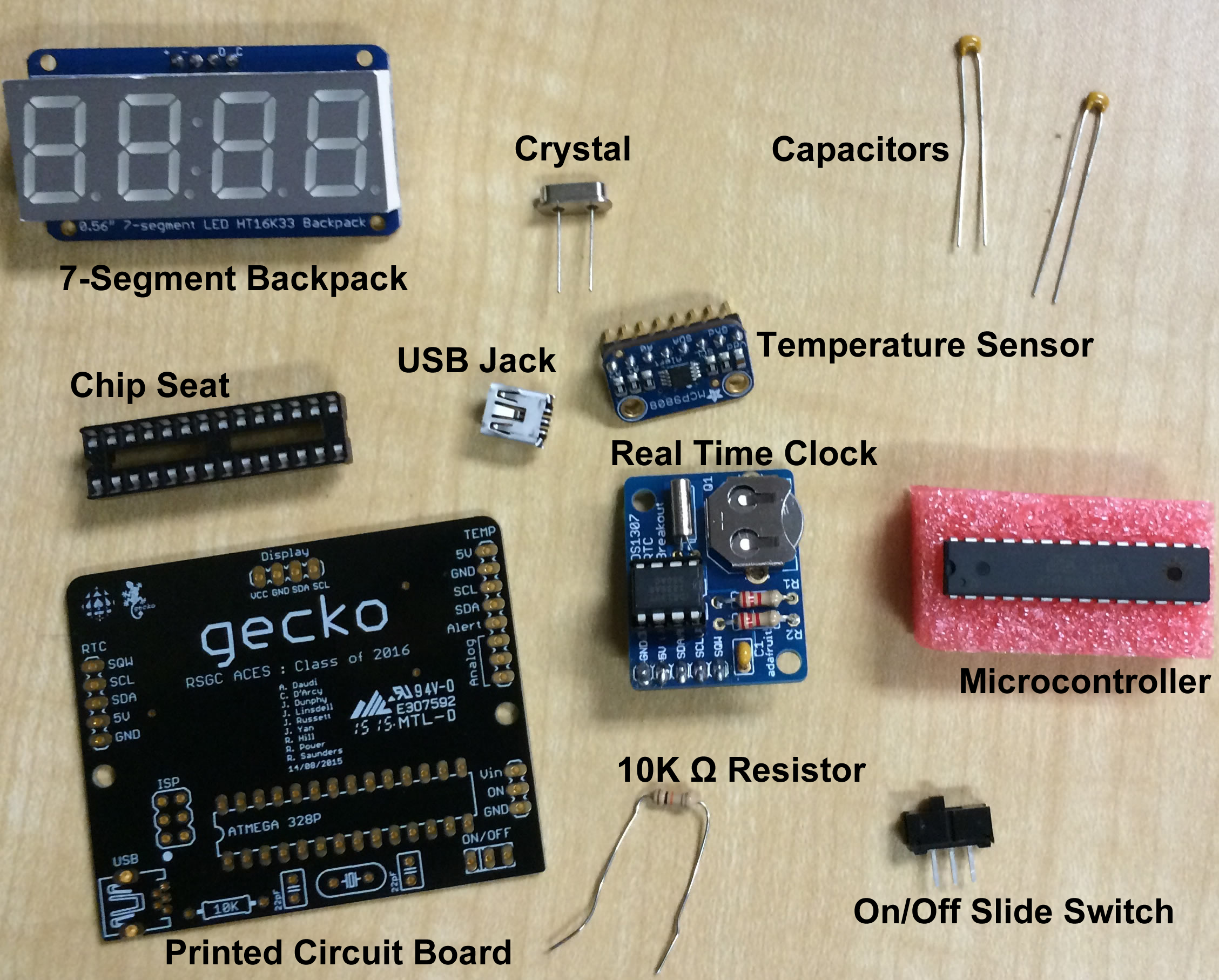
- Familiarizing yourself with the names of the electronic components ahead of time will result in a smoother, more accurate build and should avoid the frustration of trying to repair difficult soldering missteps.
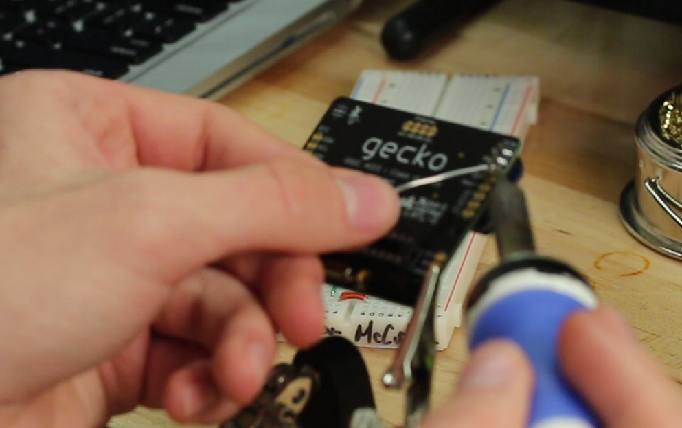
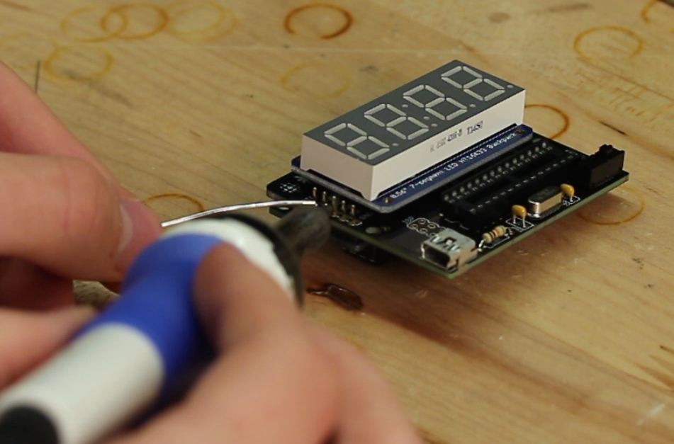
- Locate a pair of safety googles in the lab, put them on and leave them on throughout the assembly. Turn on the soldering station, adjust it 300°C, no higher, and turn on the exhaust fan. Locate the temperature sensor and solder the 8 male header pins to the small board, keeping the soldering tip clean as you go by dipping it into the brass wool. Note: Applying the solder tip to a component leg for longer than 5 seconds can potentially damage an active component, so be efficient. Solder the temperature sensor to the Gecko, from the back, on the right.
 |
Put the short end of the header into the temperature sensor and the long end into the Gecko. |

- Look at this diagram as a reference to solder the chip seat.
|
Solder ONLY the holes indicated! |
- Locate the outlines for the capacitors, the resistor, and the crystal along the lower edge of the circuit board. Place the parts in the holes and, using a pair of reverse tweezers to keep the components tight to the board, solder them in. Remember, 5s max! on each leg.
- Solder the switch onto the on/off pads. The orientation is not important.
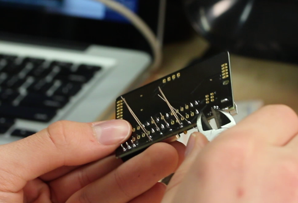
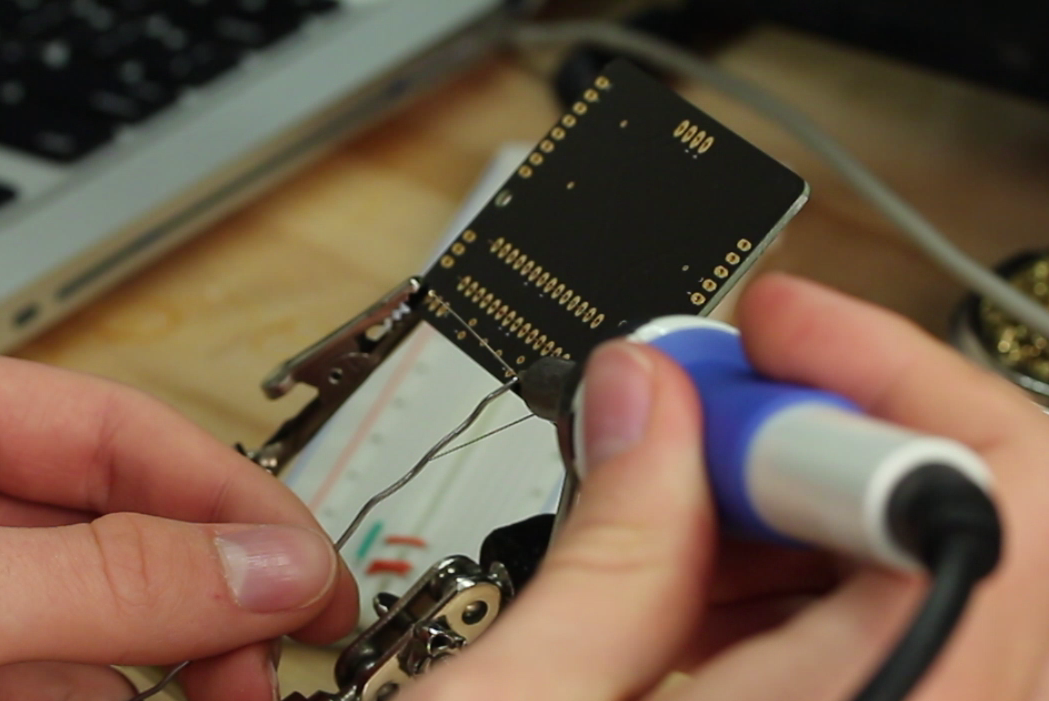
- Ensuring you have your safety goggles still on, use a pair of side cutters to clip all of the pins sticking out of the board to give the Gecko a sleek, polished look.
|
Do not clip the pins too short. Leave some length in case you need to re-solder. |
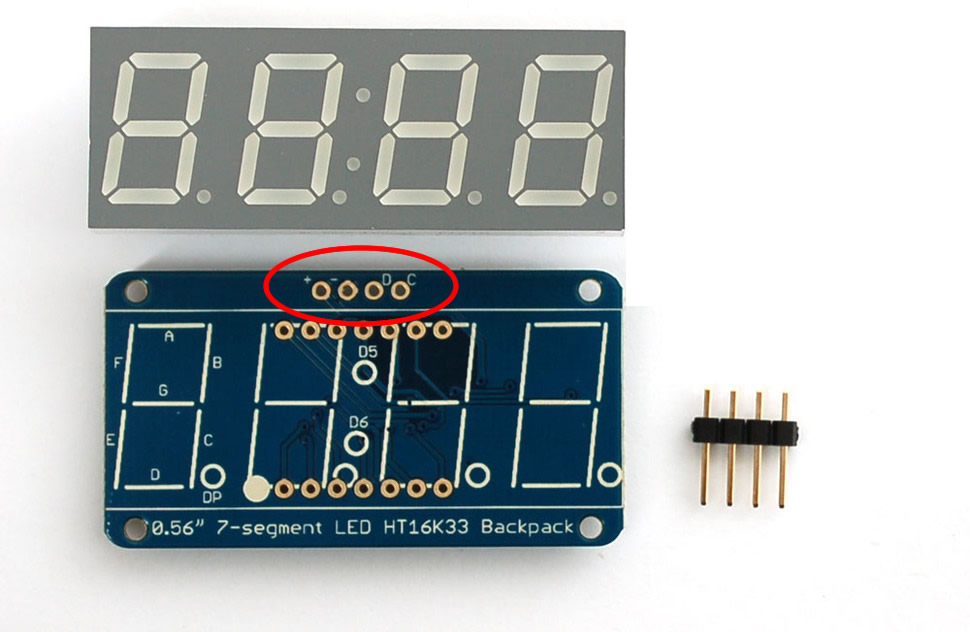
- Insert the display bank of four 7-segment digit into the front of the backpack. The front can be identified by the characters + - D C along the top. Solder all 14 pins from the back of the backpack. Insert the unit into the circuit board, soldering the four pins. Make sure it is upright and on the board.
- Clip the four headers off the display to allow for the installation of the Real Time Clock (RTC) in the next step.
- Solder the RTC on the back next to the temperature sensor. Do NOT clip the header pins to make it easier to possibly reprogram the RTC in the future.
- Place the microcontroller into the chip seat making sure to align the reference notches on each.
- Plug in the Gecko and turn it on. If everything was done correctly the Gecko should be flashing the current time before rotating through the other displays.
 RSGC ACES