2021-2022 ICS4U Independent Study Projects (ISPs) |
![]() Independent Study Projects. Please read our overview on why ACES pursue Independent Study Projects so vigorously.
Independent Study Projects. Please read our overview on why ACES pursue Independent Study Projects so vigorously.
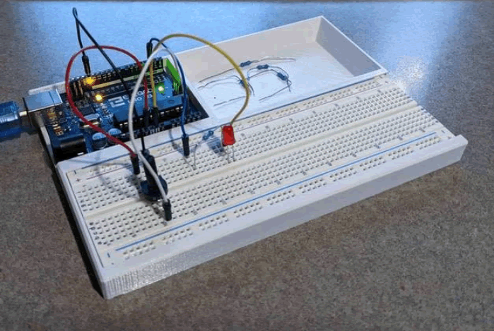
 To my mind, the characteristics of a great project include such aspects as imagination, creativity, a degree of risk and, sometimes, even simplicity, to name a few. Check out the flashlight circuit 'board' this guy made out of little more that a piece of paper and a pencil? Simple, but inspiring.
Consider a problem that needs a solution. Boyan Slat did at age 17 when he was in high school; four years later he is
To my mind, the characteristics of a great project include such aspects as imagination, creativity, a degree of risk and, sometimes, even simplicity, to name a few. Check out the flashlight circuit 'board' this guy made out of little more that a piece of paper and a pencil? Simple, but inspiring.
Consider a problem that needs a solution. Boyan Slat did at age 17 when he was in high school; four years later he is Also, don't underestimate the value of an enterprise/entrepreneurial aspect to your project that could see a number of units of your project in the hands of future ACES, for sale in the Dragon's Lair or beyond, reaching an even a broader audience.
| ACE | Short ISP (20%) Saturday September 18 |
Medium ISP (20%) Saturday December 11 |
Long ISP (20%) Monday February 21 |
|---|---|---|---|
| Proposals >>> | Short ISP Proposal | Medium ISP Proposal | Long ISP Proposal |
Cassano, L.
|
Cassano Desktop Mini Fridge
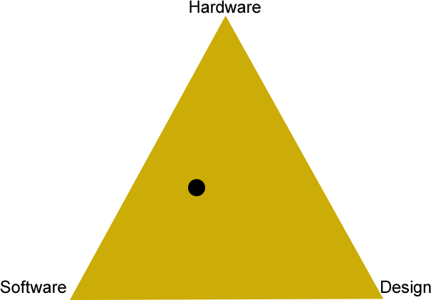
HARDWARE A 328p will be used as a standalone Arduino for the control electronics. SOFTWARE Libraries: Adafruit temperature control, Liquid Crystal Display. The software will be programmed using Arduino C in the Arduino IDE. DESIGN This is an image of the device I plan on improving... COMMUNICATION for this project I will be using Serial(ISP) communication to program the Arduino As it will be embedded in the circuit. MECHANICAL Peltier Tiles will be used to cool the inside and DC CPU fans will be used to dissipate heat from the heatsink. |
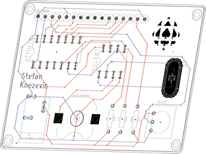
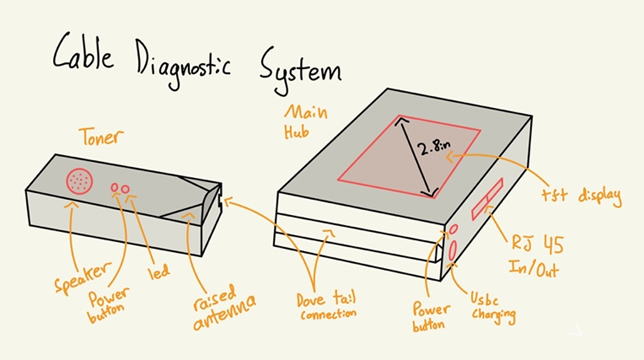
Cassano Cable Diagnostic System
HARDWARE The MCU chosen for the main hub is an ATMEL 2560 SMT chip. This was chosen for the large number of pins. Other supporting components include a 2.8in tft display, Female RJ45 and USBC ports, induction coil, lipo battery and a BMS. The MCU chosen for the toner is the ATtiny 84. Other Supporting components include an antenna, LiPo battery, BMS and an LED. SOFTWARE The Software for this project will be completed in two stages. First the Main Hub will send signals through the cable being tested and check to see if the signals received match or if they have interference. Next a 2.8 tft display will be programed as a very User-Friendly interface. The Toner will be programed to amplify the signal received on the antenna to the speaker DESIGN The Design for this project will consist of a 3D printed enclosure for both devices. Tight tolerances will be used and if time permits an SLA case may be manufactured to give the project a more professional look. Custom PCBs will be used for both devices. The toner MCU with supporting electronics will be fully SMT while the Main hub will consist of a mix of THT and SMT. |
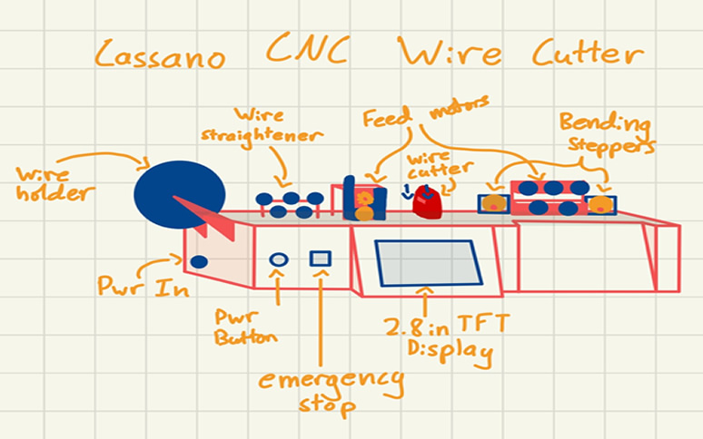
Cassano CNC Wire Cutter
DESCRIPTION The Cassano CNC Wire Cutter will aim reduce the cost of custom length breadboard wires. This CNC wire cutter will allow a user to input the desired length of wire on a touch screen, select how much wire is to be stripped from either end and the bending points. The Adafruit 2.8in TFT will be used for the UI, 3 stepper motors will be used to bend/ cut wire and the ATMEGA 2560 will be used as the MCU. HARDWARE ATmega2560 |
Chin, X.
|
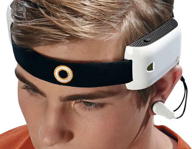
EEG Mind Control Headset
HARDWAREThe MCU chosen is an ESP-32 mainly for its in-built Wi-Fi and Bluetooth. Other supporting components may include op amps to boost the dampened brain signals picked up by electrodes. SOFTWARELibraries: Wi-Fi, Bluetooth The software will include the Arduino IDE to program the ESP-32 and Processing to visualize the different brainwave signals that are picked up by the headset. DESIGN EAGLE will be used to design a PCB to hold the electronics while a case designed in Fusion360 will hold it along with any other peripheries. COMMUNICATION Bluetooth or Wi-Fi will serve as the main communication type. MECHANICALn/a |
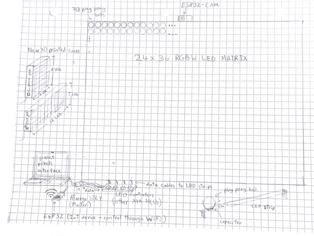
Giant RGBW LED Matrix V1 DESCRIPTION The hardware consists of a large array of SK6812 RGBW leds with supporting resistors and capacitors if need be. Both an atmega328P type MCU and an ESP32 will be used to control the large matrix for benchmarking and assessing efficiency. HARDWARE The hardware consists of a large array of SK6812 RGBW leds with supporting resistors and capacitors if need be. Both an ATmega328P type MCU and an ESP32 will be used to control the large matrix for benchmarking and assessing efficiency. SOFTWARE The main portion of the ISP is software based in which efficiency is key. Driving a large amount of rgb leds is difficult and requires knowledge and implementation of register and assembly level techniques instead of reliance on libraries. There are a few very efficient libraries such as the fastled library, but that library does not currently support sk6812 RGBW leds, a further reason to develop my own code. Along with that, there must be some way to control the matrix so for this, some sort of app or interface will be built to control the leds. If time permits, I will make a library out of my code. DESIGN The matrix will consist of PCBs each with an 8 × 8 RGB leds where they can connect together to form different sized matrices for a modular design. A 3D printed case will be made for the matrix and if needed, a wooden board will serve as the backing of the matrix for structural support. Some sort of diffuser will be used to better display the colors. |
Giant RGBW LED Matrix V2
MCUs ATtiny85, ATmega328P, ESP32 DESIGN Case COMMUNICATION Serial, SPI, I2C and WiFi |
Colraine, J.

|
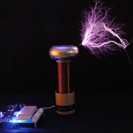
The Colraine Coil
HARDWARE The device will most likely utilize some form of microcontroller such as the Arduino UNO or ESP 32 to manipulate the frequency output. If time permits an SD card reader may also be used to upload specific patterns and files that the coil could play. SOFTWARE Libraries: Arduino SD library, Melody The Arduino SD library may be used to allow for files to be read and used. The library Melody may also be used to translate notes and rhythms into frequency and square wave patterns. DESIGN Because a Tesla Coil can produce extreme magnetic, electrostatic, and radio frequency field a case to house the electronic components will need to be made that can withstand these effects. The coil itself will be made of a length of PVC tubing wrapped in copper wire with a conductor at the top and other components such housed below the base. COMMUNICATION RF fields generated by the coil itself. (Not really communicaton) MECHANICAL n/a |
The Helping Claw Mk2
SOFTWARE The StepperDriver library will most likely be used to control the steppers motion because of its ability to support micro stepping. This will allow for much more precise motion which is important for an arm with a larger reach as small steps will result in an overall larger distance covered at max range. Another library may be used to control the joysticks or the customized library I created last year could also work DESIGN The entire structure of the arm will be designed 3D printed in a lightweight PLA filament to support the weight restrictions of the arm. The base may be printed in a stronger filament instead because it will carry the most load and not need to be lifted by the shoulder stepper. A Custom PCB may be designed if time permits which will contain pinouts for the stepper drivers and the ESP or other. |
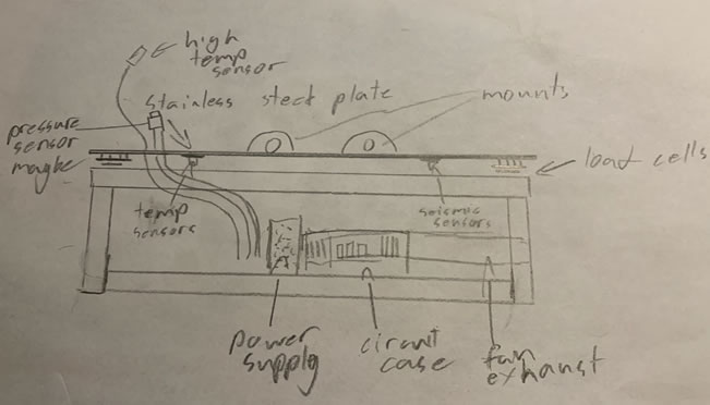
The Extreme Sensory Testing Integrated Circuit Lab
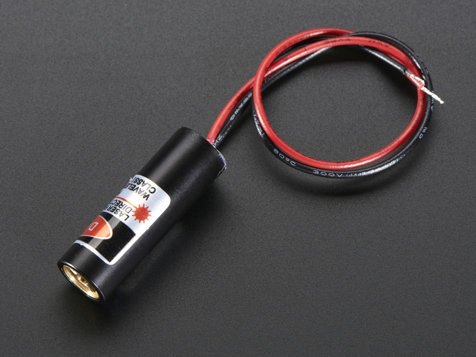
DESIGN A custom PCB will contain all circuitry and interfaces for the sensory equipment. It will contain an ESP32 or similar as a microcontroller for this equipment. The PCB will be housed within a vented and cooled 3D printed case alongside a power supply. The structure of the test bench will be made of metal brackets topped by a stainless steel sheet as a protective cover as well as a potential secure mounting point for test subjects. COMMUNICATION The test bench will use either WIFI or Bluetooth with the ESP32 to transmit data to a receiver not in range of whatever experiment is taking place on the test bench. |
Duckman, J.
|
Duckman NeoBlocks
HARDWARE The hardware in the project will not be highly advanced as all that will be applicable will be the NeoBlocks as well as a control center, including the ESP32 for WIFI capabilities. SOFTWARE Libraries: FastLED Within the Duckman NeoBlocks’s ISP, the fast LED library will be used to program NeoBlocks’s through a WIFI controlled website in which the user will be able to manipulate the NeoBlock’s in many ways. DESIGN Duckman NeoBlocks will be to a commercial standard consisting of 3-D printed cases designed through Eagle, and a Fusion 360 PCB printed through JLC and an acrylic finish to each NeoBlock. All of which will then be magnetically compatible with a magnetic board. COMMUNICATION Duckman NeoBlocks will be able to be controlled via WIFI using its MCU the ESP32 MECHANICAL n/a |
Duckman Delightful Docket HARDWARE The circuit in this project will be quite minimalistic, evolving a speaker, ATtiny 85, some binary switch, a variety of flashing LEDs and a piezoelectric buzzer. In addition, a flat flex cable breakout must be used to program the ATtiny85. To power this circuit, I plan to use two 3V lithium coin cell batteries in parallel to allow a longer-lasting gift. The major problem to overcome within this domain is space, as when creating a card, a receiver expects it to be pretty much flat; therefore, the least number of intrusions possible is the goal. SOFTWAREThe software in this project will evolve two different components. The first is programming a sensor allowing a tune to play once the card is opened. And the second is the tune that will be played over the buzzer. DESIGN The design of this project will be advanced, evolving the card's design in addition to a custom D.D.D. (Duckman Delightful Docket) P.C.B. In addition to such, I may make a switch to gage when the card is opened, which will occur if I am unable to find a sensor to my liking. The card's design will be highly similar to any other cards, with my ultimate goal of making it as high quality as possible. It will evolve the RSGC crest in addition to different RSGC themed designs. |
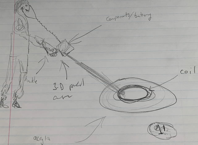
Duckman Metal Detector
DESCRIPTION The Duckman Metal detector is a project built to understand a concept that interested me growing up metal detecting. It will be a build complementing each of the three ACES domains software, hardware and design. Despite the apparent domains being hardware and software, the design potion within this project will involve an acrylic saucer, a PCB and a 3-D printed case. The acrylic saucer will be housing the coil creating a modern look. The PCB will play the prominent role of the circuit and be housed within the 3-D printed case. |
Goodwin, J.
|
The (Upgraded) PSR-172 Piano Keyboard
HARDWARE 328P or ATtiny84 SOFTWARE ? DESIGN The 3D printed case will mostly likely attach onto the side of the keyboard fitting into an indent on the top of the case. The PCB will secured to the bottom of the case with standoffs and screws. COMMUNICATION The MIDI communication protocol will be used to communicate with the computer to send the note and velocity data. MECHANICAL None except for custom-designed, 3D printed mechancial pivot/hinge system for keys |
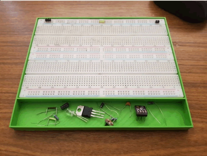
The Goodwin 8-Bit Computer HARDWARE The Goodwin 8-Bit Computer will be capable of a variety of logical and arithmetic operations including but not limited to: bit-shift, multiply, divide, mod, and, or, xor, and more. This will be accomplished by using 74LS181 along with some extra circuitry to accomplish the other operations. The computer will be capable of comparison operations as well. It will have 2 8-bit IO registers which can each be set for input or output. This is determined by a data direction register. The computer will have access to 2k of EEPROM. The EEPROMs will be chained together to make it possible for a 8-bit opcode and 8-bit value to be stored. The amount of RAM is currently uncertain due to many of the TTL ram IC’s no longer being sold. I will go to A-1 electronics to see if I can find something preferable. Ideally the computer will be able to run at 1 MHz or greater. The clock frequency is limited by the accessing times of the EEPROM and RAM. I will try to complete what I have promised but I may add more. SOFTWARE At a bare minimum I plan on having my computer control an 8x8 LED matrix to demonstrate its output capabilities. I will try to complete what I have promised but I may add more. DESIGN The project will be built on breadboards. There will be no CAD in this project unfortunately. |
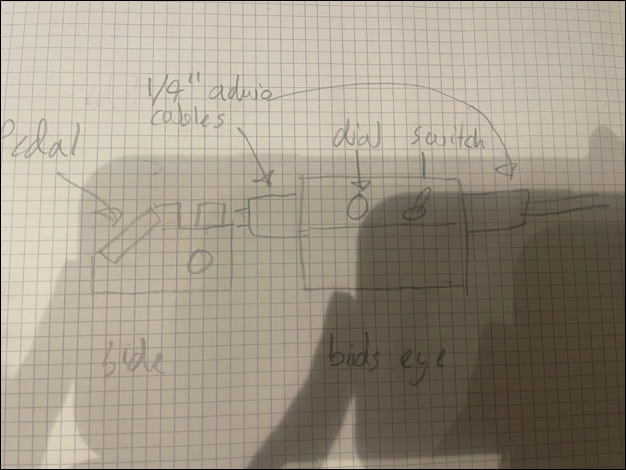
The Goodwin Distortion Pedal
DESCRIPTION The Goodwin Guitar Pedal will be able to provide distortion effects for an electric guitar. It may feature different circuitry to create different types of distortion. The distortion effects will be created using passive and active components. The case will be 3d printed and a PCB will be created for the |
Langill, D.
|
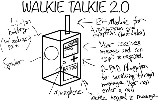
Walkie Talkie 2.0
HARDWARE I plan on using the 328P, but if I am able to optimize the hardware, I will switch to a smaller mcu. SOFTWARE Libraries: RF24, LCD (might need to make own), KEYPAD (might need to make own) Further Details… As you might tell, the specific libraries I use for the LCD and KEYPAD are not determined as I have yet to determine the exact models I want to use. DESIGN The device will require at least one PCB created via eagle and manufactured using JLCPCB, and a case I will design myself through Fusion360. COMMUNICATION The two devices will communicate with each other using Radio Frequency technology, however the components used within the device itself may utilize the SPI or I2C protocols. MECHANICAL n/a |
The Langill Matrix
SOFTWARE While Software Serial, I2C and shift out libraries/functions already exist built-in to the Arduino development environment, they will not be used. Instead, all software will be attempted without libraries. This approach serves to increase the speed of the MCU and benefits my own development. DESIGN The Langill Matrix will be initially prototyped on a breadboard using through-hole components. However, afterwards a surface-mount PCB will be created via EAGLE and manufactured using JLCPCB. I plan to utilize JLCPCB’s SMT assembly service provided the parts are in stock. If enough time presents, I will also create a simple 3D printed case to hold the PCB. |
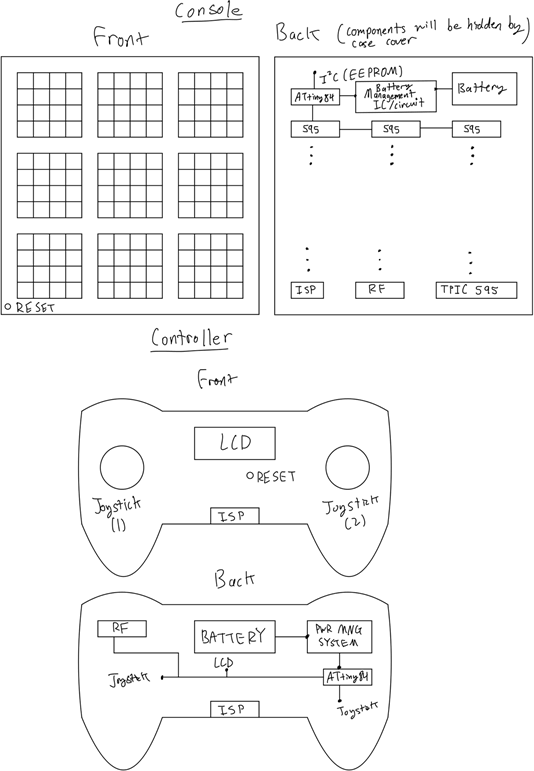
The Langill Matrix Console
DESIGN Two EAGLE designed PCBs for controller and console; both designed to fit custom Fusion 360 3D-Printed cases. The console PCB may need to be split into two, but will hold the matrices, and supporting electronics. COMMUNICATION RF: controller and console I2C (most likely): External EEPROM (if needed) SPI: shift-registers and in-system programming |
McDonald, H.

|
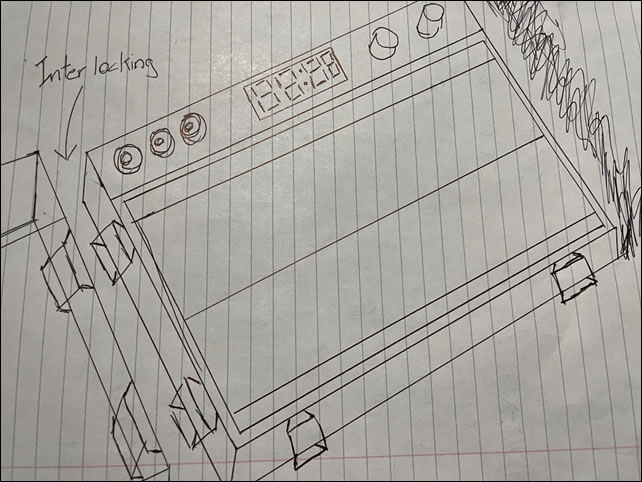
ACES CHUMP CUSTOM PROTO STATION
HARDWARE The case will use a ATmega328P to handle conversion from the binary byte into hex. SOFTWARE Libraries: None.The project has very little software, a look-up table and some register level pin manipulation is all that’s needed. DESIGN The Design portion of this project is the most Significant. Many Iterations will go toward perfecting a CHUMP enclosure everyone is happy using. The feel, look, shape, texture and colour are figured out in this step. I will be using Fusion360 and hope to also use Acrylic for a window. COMMUNICATION I2C (CD:Hmmm...) and any other communication busses within the CHUMP MECHANICAL Unfortunately, the CHUMP encloser will not have any moving parts. I want the machine to be as rigid as possible, eliminating the possibility for a servo or motor. |
TTC Train Tracker
SOFTWARE The program flashed onto the TTC Train Tracker’s microprocessor must take advantage of tri-state logic. The shear number of stops needing a red and green connection means nearly every I/O pin will be used up. The use of interrupts will make a more reliable system. Meaning the duration at which the LEDs switch will drift less over time DESIGN The TTC Train Tracker will be no larger than four credit cards thick. Each station will have the name inscribed into the silk screening above or under it with the “TTC Train Tracker” title also being printed but in a much larger font. A thin 3D printed case will snap to the back of the card to protect the coin cell batteries. The PCB will be designed in Eagle and the case in Fusion360. The TTC Train Tracker will be built on a matt black PCB and protected by a Galaxy black case. |
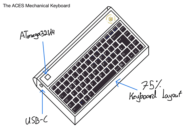
The ACES Mechanical Keyboard
DESIGN The project's frame and largest parts will be printed in Galaxy Black PLA with smaller details printed in yellow. Sandwiched between the keys and the PCB is a gray frosted acrylic plate that improves how rigid the keyboard is. COMMUNICATION For programming the device, a ribbon cable will be used to transmit SPI data. Optionally, Serial programming is possible over the USB-C port. One wire commutation will connect the Neopixels. MECHANICAL The switches I plan on using are known as machinal switches because the internal mechanics are far superior to regulator THT or SMT switches a new name had to be developed for them. Nothing truly makes these precision switches any more mechanical than their cheaper counter parts, they both switch on and off current, but company’s still like to market them as so. Specifically, I chose the Cherry MX red switches for their light operating force and long-life span. |
2021/2022 Short ISP Choices
ISPs are gifts. The best choice for you is the one that fits well with your interests, as well as strengths, and blows the doors of your future opportunities wide open!
It takes CONSIDERABLE time and reflection to make the BEST ISP choices but, the good news is that this year you have more options than ever before. For the 2021/2022 ICS4U-E year, the starting point for your Short ISP can come from any of the following four areas (no group projects and no duplications),
 As you wind up the final two terms of your secondary education it is time to both advance and lock in your burgeoning engineering skills. Whereas through-hole technology (THT) has had a good run over the past few decades, the future is Surface Mount Technology and Design. For this reason, you best be prepared. This ISP round you will refine your SMD and CAD skills to showcase your Design skills in preparation for the opportunities that await you in the next few years.
Your Medium ISP goal (20% of your final mark) should include the slimmest of useful DES devices consisting of a custom PCB, populated with SMT parts, and encased or hosting (Truth Be Told, Mastermind) 3D printed components in the thinnest form possible (think wallet-size proportions). You have two months. Our 3D Printing TAs, and either JLCPCB or DirtyPCBs are all about to get a serious Sr. ACES workout.
Should you be stuck for a meaningful project, consider a DDPv7 Legacy Shield to complement or replace the ones we already have (Intersection, ADC, Universal v1 or Universal v2). The only stipulation I impose is that these devices must remain compatible with our current EAGLE DDPv7/Shield files.
Download and review the updated Medium ISP Proposal. This Word version I would ask that you edit, attach, and email on Saturday December 11, 2021 under the Subject Line: Medium ISP Proposal.
Long ISP (THT and/or SMT, Fixed or Flex)
 Download and review the updated Long ISP Proposal. This Word version I would ask that you edit, attach, and email to on Monday February 21, 2022 under the Subject Line: Long ISP Proposal.
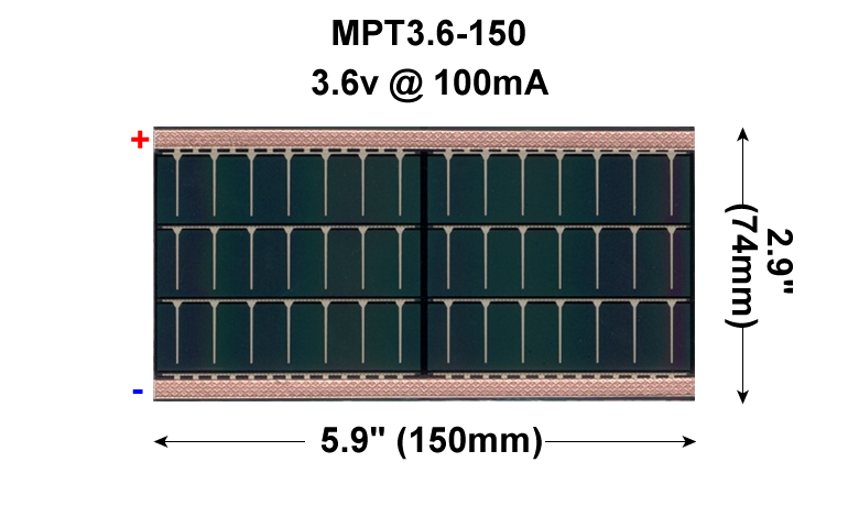
Electronic control over your final ACES ISP must be in the form of custom PCB populated with either through hole and/or surface mount components. In the case of the latter, you can consider taking your design to the next level, in the form of a Flex circuit that will be laminated into a page of your DER. If your circuit proves fully functional a flexible 3.5V, 150 mA Powerfilm solar cell will be included in the lamination so that that viewers of your creativity will marvel at when shown the light of day!
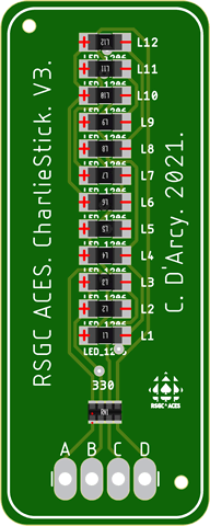
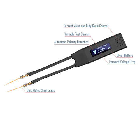
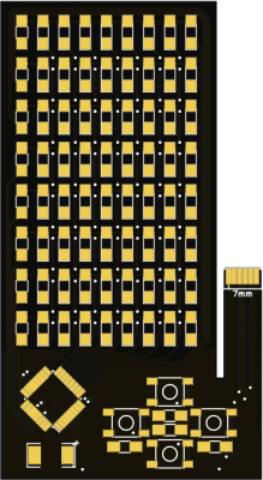
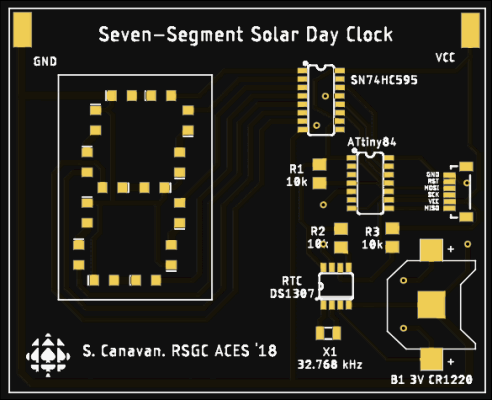
![]() The Flex Circuit concept was first introduced into the ACES curriculum in the 2015/2016 TEI4M year with some impressive results. Where the attempts since have failed is whren the designer becomes too ambitious. If you choose this route, I require that you keep it SIMPLE. (LEDs and resistors only?) Your Medium ISP requirements provided you with valuable experience that should improve your likelihood of success as will be a small project this term that requires the use of the ACES ATtiny85 SMD Trainer. The examples below are too ambitious for us but each offers a unique feature you may wish to consider,
The Flex Circuit concept was first introduced into the ACES curriculum in the 2015/2016 TEI4M year with some impressive results. Where the attempts since have failed is whren the designer becomes too ambitious. If you choose this route, I require that you keep it SIMPLE. (LEDs and resistors only?) Your Medium ISP requirements provided you with valuable experience that should improve your likelihood of success as will be a small project this term that requires the use of the ACES ATtiny85 SMD Trainer. The examples below are too ambitious for us but each offers a unique feature you may wish to consider,
| Grade | Contribution to Final Mark |
|---|---|
10 |
30% |
11 |
40% |
12 |
60% |
For the bulk of your formal education you have been, and will continue to be, required to consume curriculum chosen for you by someone else. Fortunately (hopefully) you will put this knowledge and skill to good use in your future. However, jumping through someone else's hoops alone does not, typically, secure future success. For that, you must demonstrate your own initiative, motivation, and passion. These qualities need to be cultivated and our Grade 10 hardware course is a perfect place to start. There is so much to learn and there are so many great projects out there that offer stimulating contexts within which to develop and refine your interests.


