| 2018-2019 ICS4U Engineering Tasks |
![]() Flex Circuit Page. Even though this description is a little long, please be sure to take it ALL in before deciding on a circuit you will be proud to reflect for years to come.
Flex Circuit Page. Even though this description is a little long, please be sure to take it ALL in before deciding on a circuit you will be proud to reflect for years to come.
YOU WILL PREPARE TWO WORKING VERSIONS OF YOUR CIRCUIT:
ONE FOR YOUR DER and ONE FOR OUR RSGC ARCHIVES!!
So, here's the basic concept. Download, consider, and complete the FlexPageProposalICS4U.docx (download first, then open, as browsers seem to have issues with its contents) when you're ready to commit.
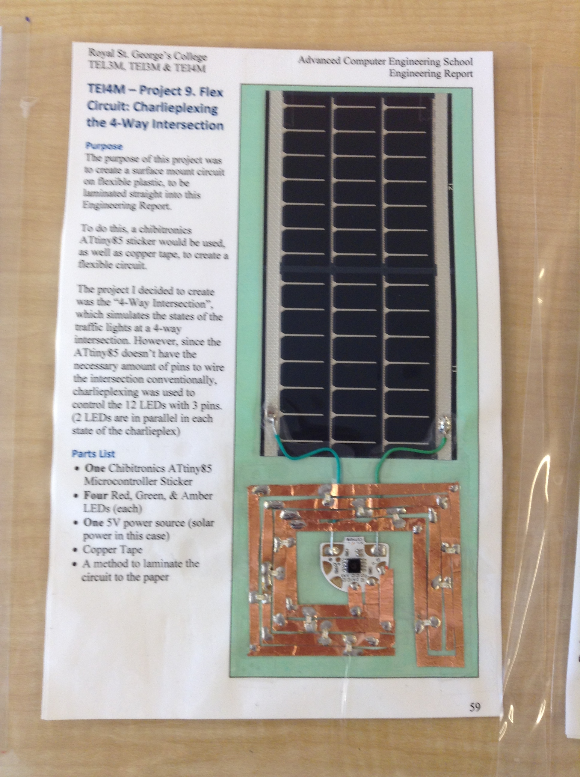
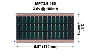
For the fourth consecutive year, Sr. ACES are asked to embed within their Design Engineering Report a unique, active, (solar-powered) microcontroller-based circuit. In the future, when you show your DER the light of day, readers will marvel at what you accomplished in high school. A photo of Ryan Power's effort from 2016 follows the formatting of all the other pages in his DER except the cutaway is an intersection circuit that goes live when placed in sunlight due the to MPT3.6-150 solar panel laminated into the page. Ryan's report continues on the backside of the page. Check out the results of all the 2015-2016 ACES.
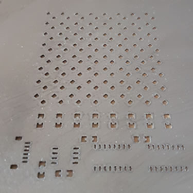
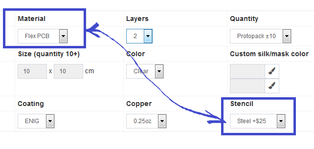
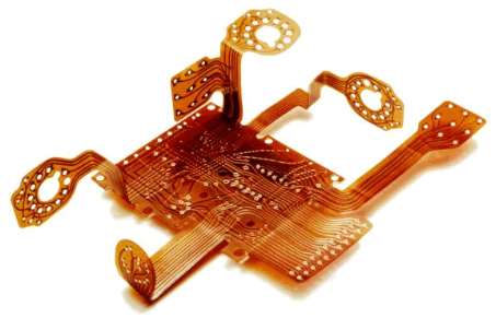
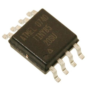
In maintaining the ACES' tradition of reaching higher, you are asked to design and outsource the production of a flex circuit as a base for an SMT circuit (and DER page). You, the 2018-2019 ACES, continue the initiative started three years ago year by incorporating a flexible circuit into a page in your DER, laminating it together with a Powerfilm solar cell to power either an SMT ATtiny84, ATtiny85, or ATmega328P surface mount microcontroller. The programming language is left up to you but since the complexity of the circuit is not the real priority, I know you'll consider putting your assembly language skills on display in your circuit and your pages. Supporting components should be designed for the 1206 Package as that's what our DES maintains in its inventory. To facilitate your efforts in getting it right the first time, you are encouraged to source as many parts as possible from our new ACES_SMT.lbr. Below is a closer look at a Flex Matrix Oliver L. undertook while in Grade 11. A stencil is recommended for complex designs as it dramatically simplifies and shortens the reflow or hot-air soldering process.
| Oliver's Finished Flex Matrix | Oliver's Flex Circuit Stencil |
|---|---|
 |
 |
| Flex Circuits & Thin Film OLED | Dirty PCB Ordering |
 |
 |
Hardware Provided
 Within reason, the hardware parts will be supplied to you. For example, you will be provided with the solar flex cell, the SMD microcontroller, as well as simple 1206 passives such as resistors, capacitors, buttons and LEDs. Just be sure to answer my call for Digikey orders promptly.
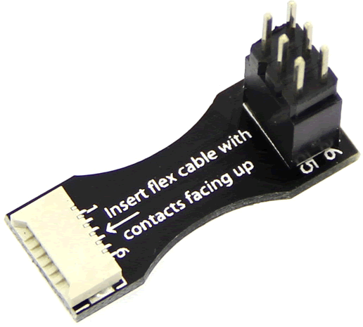
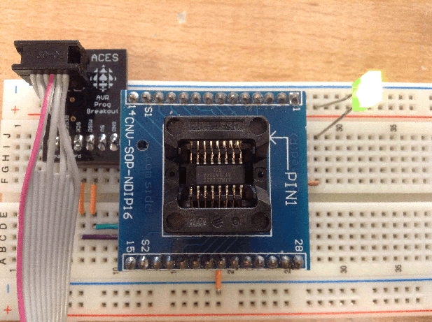
In return, you can be responsible for the cost or your flex panel. On this score, since your microcontroller must have an ISP capability, be sure to design in a 6-pin connection that will interface with the Chibitronics device pictured to the right.
Resources
 ACES: Common
Flex Page
Parts
ACES: Common
Flex Page
Parts
Minco: Flex Circuit Design Guide
ACES: 2016-2017 TEI4M Logs
PowerFilm: Flex Solar Cells
Adafruit: SMT (Medium) Test Socket for SOIC-8
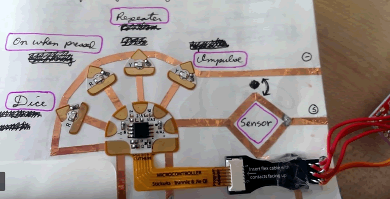
Chibitronics: ATtiny85 Sticker Tutorial (that ISP Adapter would be a good board to have in the DES!)
Quad Industries: Screen Printing
Sparkfun: IC Packages Explained
Videos
![]() The MPT3.6-150 Solar Module, (Specs)
The MPT3.6-150 Solar Module, (Specs)
![]() Pro SMT Hand Soldering: Part 1, Part 2
Pro SMT Hand Soldering: Part 1, Part 2
![]() Soldering Powerfilm
Soldering Powerfilm
![]() P. Bagga's (ACES' 17) SMT Soldering of his DC Power Breakout Board (a little too much solder paste but it still worked)
P. Bagga's (ACES' 17) SMT Soldering of his DC Power Breakout Board (a little too much solder paste but it still worked)
![]() J. Russett's (ACES '16) Flex Page Circuit: Induction
J. Russett's (ACES '16) Flex Page Circuit: Induction
![]() A. Elder's (ACES '17) Flex Page Circuit: Infrared Receiver
A. Elder's (ACES '17) Flex Page Circuit: Infrared Receiver
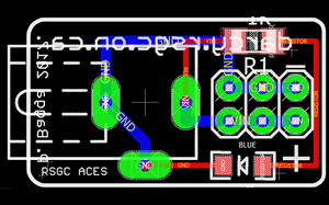
![]() O. Logush's (ACES '18) Flex Page Circuit: 'Charlie'flexed Matrix
O. Logush's (ACES '18) Flex Page Circuit: 'Charlie'flexed Matrix
| ATtiny85 SOIC-8 | PowerFilm Solar Cell / Surfboard 9081 |
|---|---|
 |
 |
Task.
| 1796-ADA SMT Test Socket - Medium SOIC-8 (ATtiny85) | 1283-ADA SMT Test Socket - Narrow Breakout SOIC-16 (ATtiny84) |
|---|---|
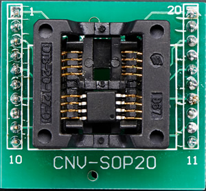 |
 |

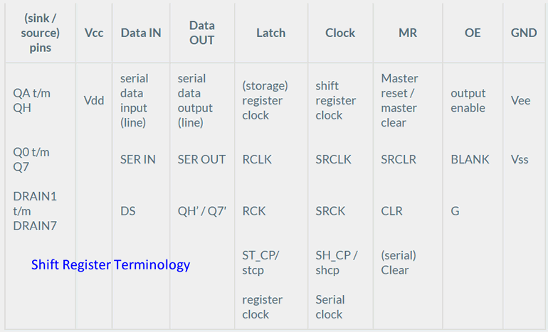
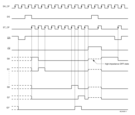
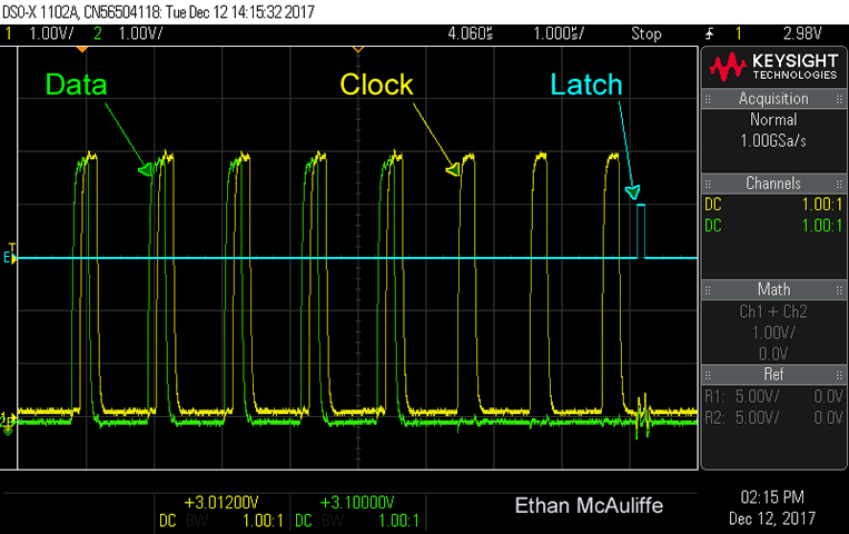
![]() Knight Rider. Your first AVR Assembly project developed exclusively in Atmel Studio 7 requires you to produce the animated sequence on your Morland ShiftBar device. Your code will employ coordinated timing sequences that will emulate Arduino C's high level shiftOut library function that we reviewed in depth on Friday January 17. Ethan McAuliffe (ACES' 18) provides us with an interesting scope trace of a 595 shift register in action that he produced on our KeySight Oscilloscope.
Knight Rider. Your first AVR Assembly project developed exclusively in Atmel Studio 7 requires you to produce the animated sequence on your Morland ShiftBar device. Your code will employ coordinated timing sequences that will emulate Arduino C's high level shiftOut library function that we reviewed in depth on Friday January 17. Ethan McAuliffe (ACES' 18) provides us with an interesting scope trace of a 595 shift register in action that he produced on our KeySight Oscilloscope.
Task.
| Shift Register Terminology | SN74HC595 Timing Sequence |
|---|---|
 |
 |
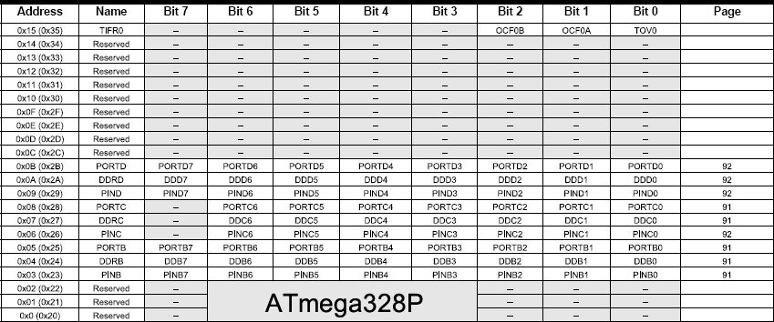
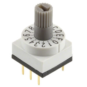
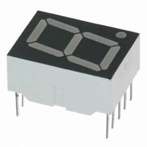
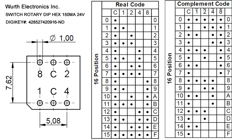
![]() Rotary BCD Switch. For your first (exclusively) assembly language project you are to CONTINUOUSLY monitor a full BCD rotary switch and display the full range of hexadecimal input on the 7-segment display provided, using the most EFFICIENT algorithm YOUR high-quality assembly coding skills will permit and the neatest, most EFFICIENT hardware build (minimally necessary components).
Rotary BCD Switch. For your first (exclusively) assembly language project you are to CONTINUOUSLY monitor a full BCD rotary switch and display the full range of hexadecimal input on the 7-segment display provided, using the most EFFICIENT algorithm YOUR high-quality assembly coding skills will permit and the neatest, most EFFICIENT hardware build (minimally necessary components).
Task.
| 16 Position BCD Rotary DIP Switch | 7-Segment Display |
|---|---|
 |
 |
![]() Telephone Keypad. You have been supplied with a 12-Key mechanical telephone keypad. Create an ORIGINAL project that positions it as the input source of some device you'll 'invent'. Your software should use some form of interrupt-handling to monitor the input. A close inspection of the circuitry in the image presented on our course page, together with a thorough Continuity review with a DMM will earn you a solid understanding of how this device is constructed.
Telephone Keypad. You have been supplied with a 12-Key mechanical telephone keypad. Create an ORIGINAL project that positions it as the input source of some device you'll 'invent'. Your software should use some form of interrupt-handling to monitor the input. A close inspection of the circuitry in the image presented on our course page, together with a thorough Continuity review with a DMM will earn you a solid understanding of how this device is constructed.
Notes.
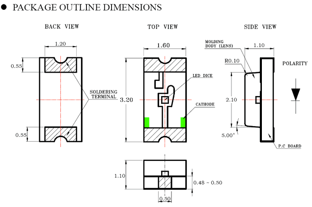
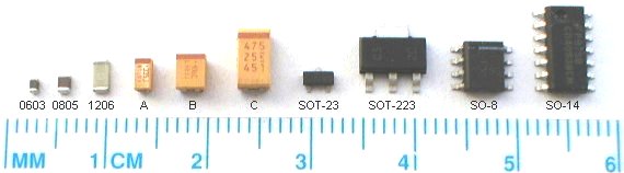
![]() PB Machine. Your experience with electric circuits has been largely limited to components that use through-hole technology (THT). To round out your proficiency with all components, your next few projects will require the use of devices that use surface-mount technology (SMT). As the graphic reveals, the smallest size that is reasonable for hand-soldering techniques is the 1206 family, so this is what we carry in the DES inventory.
PB Machine. Your experience with electric circuits has been largely limited to components that use through-hole technology (THT). To round out your proficiency with all components, your next few projects will require the use of devices that use surface-mount technology (SMT). As the graphic reveals, the smallest size that is reasonable for hand-soldering techniques is the 1206 family, so this is what we carry in the DES inventory.
DC Jack PCB |
1206 LED Package |
|---|---|
 |
 |
Task.