 Flexible Circuit (Let's blaze trails one more time)
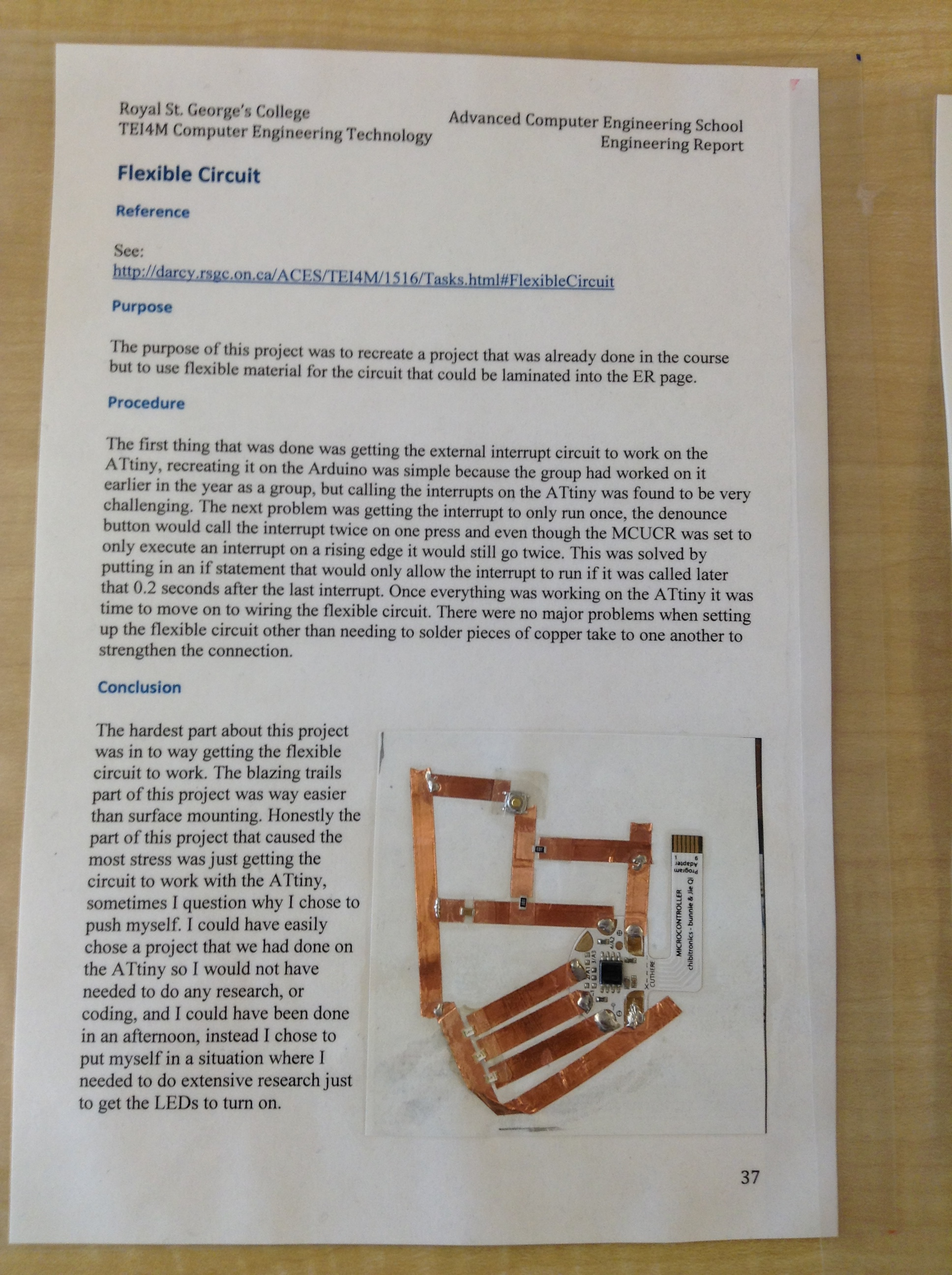
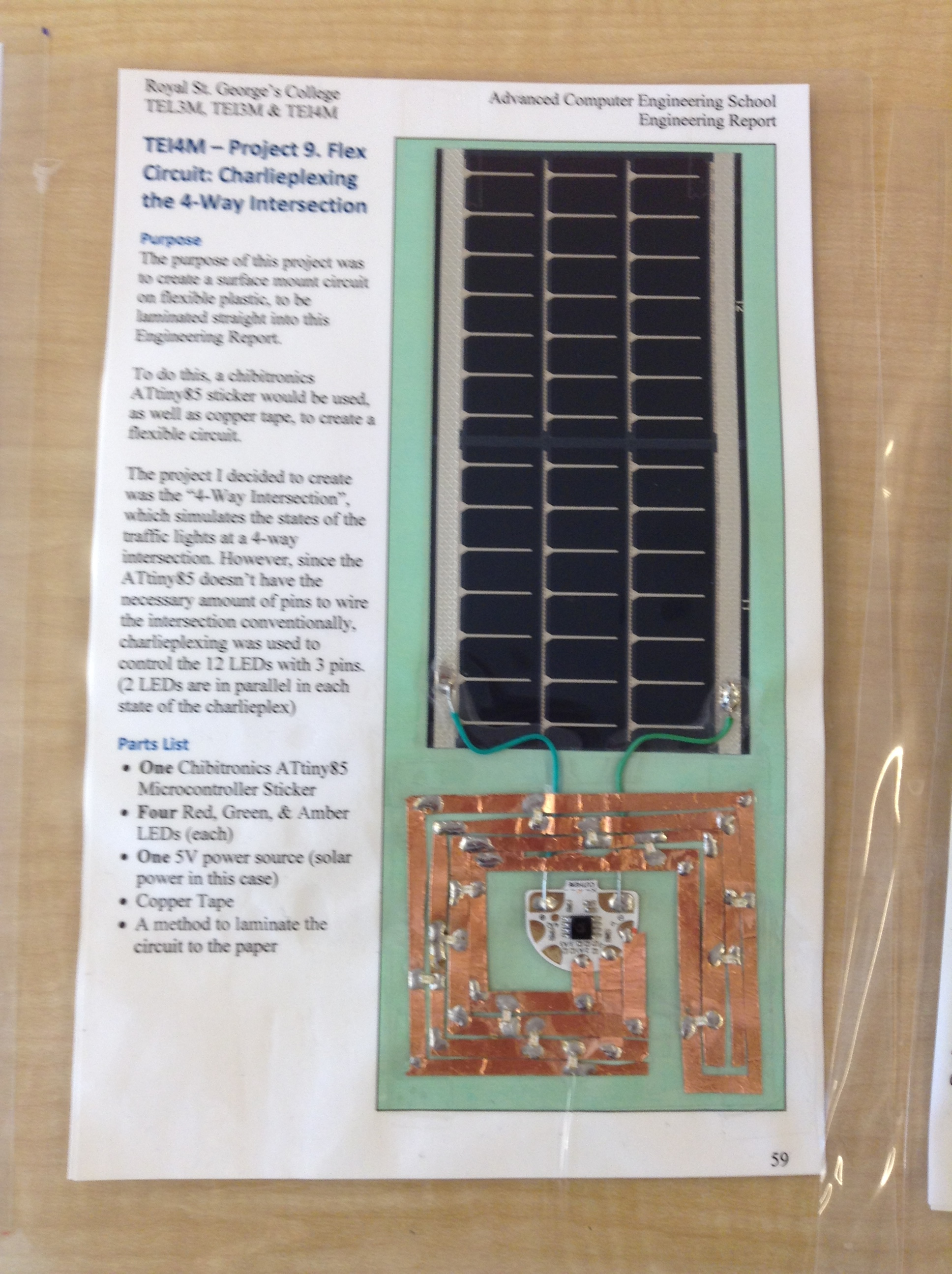
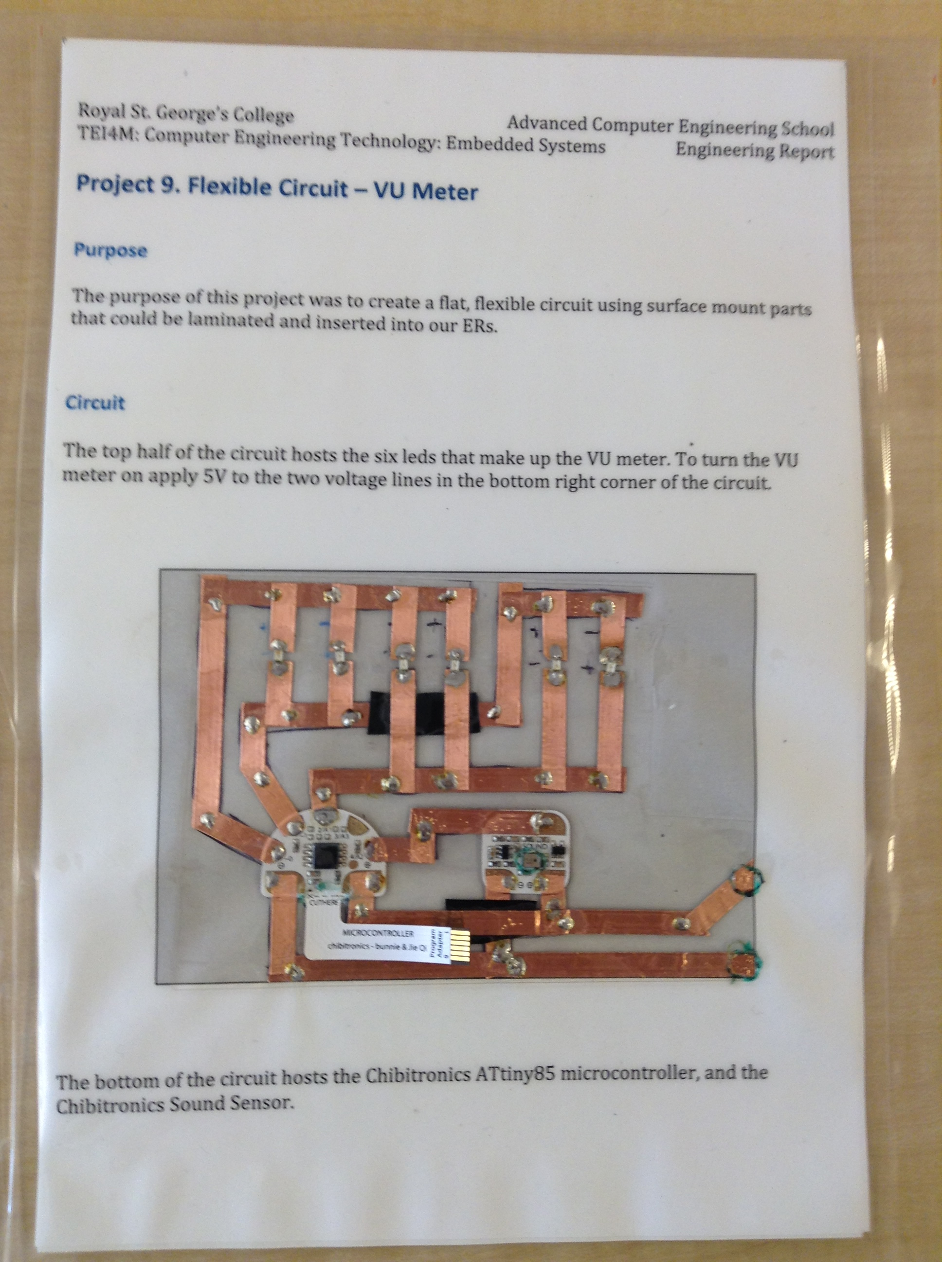
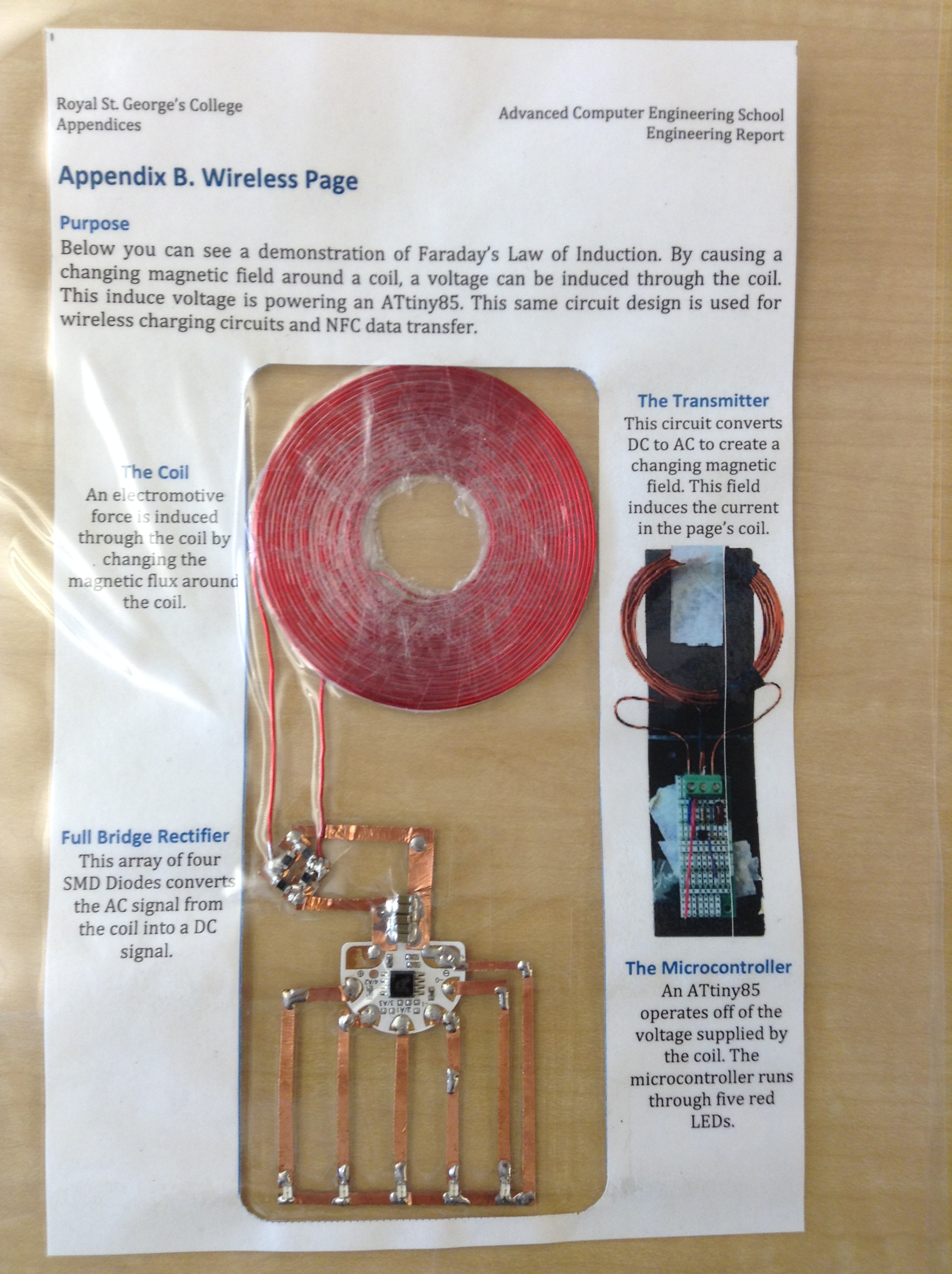
In this RSGC ACES first, you will create a double-sided, laminated ER page containing an embedded ATtiny85 microcontroller circuit driving surface mount components (mono- and bi-color LEDs, buttons, etc.), complete with integrated solar power source, that will be bound into your ER document with the other pages and presented to you at graduation.
Sound crazy? Not really (it's quite doable); all that is needed is your imagination (you have all the other skills).
Task.
- Imagine, design, and implement an ATtiny85-controlled circuit that uses low profile, surface mount components (with copper tape for traces; Z-tape for connections), to achieve a compelling result.
- Despite the fact that the ATtiny85 microcontroller is embedded within a laminated page, it must remain reprogrammable. Yikes!
- Your integrated solar power source should also be accessible externally in the event you wish to use it for another purpose.
- Laminated within the double-sided page is your ER summary, as close to your preferred style as possible. Be creative with this. For example, images with integrated LED backlighting could make for an attractive visual effect. As well, annotated schematics integrated with the actual circuit would be highly informative.
Possible Ideas
- Charlieplexed LED Matrix. Underlay for displaying 2D shapes, Cellular Automata, Game of Life, 3D Platonic Solids, Constellations, etc.
On Friday April 22 you will hand me your ER page for safekeeping and I'll ensure it's bound into your ER in June. .
Here are the (incredible) results :)
 Liquid Crystal Display: Direct Drive.

 You are free to discuss any and all aspects of the THEORY of the operation of this project with your peers and myself, but the wiring and code you produce will be entirely unique from that of any of your peers. I know you'll respect this.
LCDs (segmented, character, or graphic) offer attractive, lower power alternatives to their LED counterparts. Due to the complexities of the AC waveforms required to drive the units, they typically come integrated with specialized ICs (ie. HD44780) attached, freeing the developer from the heavy coding, but adding to the cost of the project. Another benefit of the integrated IC is the sheer number of segments that a glass may have that tends to swamp most microcontroller-only solutions (we'll use shift registers in this project to overcome this limitation).
 In this project you are asked to drive an LCD directly through the coordination of an AC signal together with data from your (DS1307) RTC. The datasheets provided in class,together with the resources archived on our ACES LCD Project Page, provide the basis for your research (you are strongly encouraged to push yourself through the research prior to wiring and coding).
Depending on the architecture of a particular LCD unit (the number of backplanes), the required AC drive signal can be described as either Static or Multiplexed, with Static being simpler to implement. I exposed you to the complexity of a multiplexing strategy in the three-level drive circuit worksheet I asked you to complete this past week.
Task.
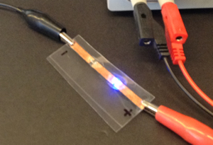
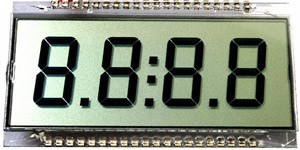
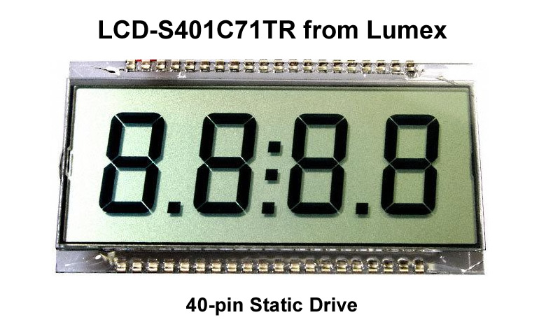
- The goal of this project to present a MM:SS display on your LCD using the data provided from your RTC. Also, the center colon should flash at 1Hz.
- The photo above right depicts the 40-pin LCD-S401C71TR from Lumex you have been provided with. As can be determined from its datasheet it is a Static (see below) drive unit making the AC waveform simpler to create. Remember, segments will appear persistently on when they are exposed to an 30Hz-100Hz AC signal of sufficient amplitude.
- ATMEL's AVR241 Application Note outlines how to interface a Static device such as this one, using general I/O pins. By the time you reach page 3 in this document you'll begin to appreciate the relative ease of the implementation and how a complex biasing strategy is overkill in this application.
- Code considerations for this project include,
- low level timer interrupt (1Hz) (do NOT use the TimerOne library)
- the bitwise XOR operation for byte inversion (data ^ 0xFF)
- the shiftOut instruction
- Use of the RTC library
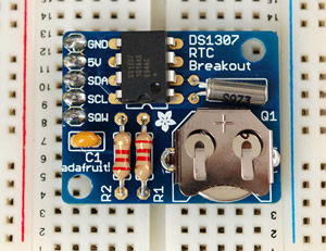
- The RTC you have been provided with is yours to keep for the balance of this year (it may be needed in a future project) but, since only one will be provided, care must be taken in soldering. I highly recommend the use of a chip seat.
- A comprehensive ER summary is due no later than midnight March 13 that must include an informative video.
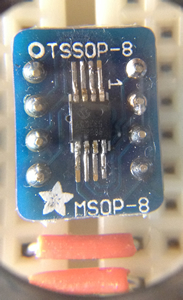
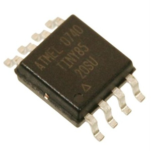
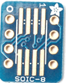
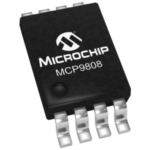
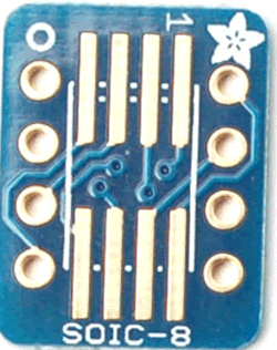
S2F: Temperature Display. (See ER Task requirements below) The objective for January is to produce a standalone prototype, as retail-ready as your abilities permit, from start-to-finish (S2F), that provides temperature/thermostatic functionality. That is, in addition to undertaking all of the circuitry and the display, you are to design and manufacture a custom case to house your device. This ATtiny85V-based project requires that you employ the SOIC-8 version of the microcontroller (below, left) and the same I2C-compatible MCP9808 temperature/thermostat IC you employed in the Gecko (below, right). Fortunately, the pinout of the MCP9808 is identical to the DS1621 we studied in class. SMT breakout boards are provided for your soldering requirements for these two ICs. Roll over the center image and take note of the spacing of the leads of the two different package types.
Your project will make creative use of the thermostat feature of the IC (ie. LED, buzzer, etc.).
Finally, consider scaling the power requirements of the device down to as low as possible to support your design.
(February 6, 2016) Well, that was an interesting start to the year. When the Grade 10 and 11 students in the years ahead are seamlessly soldering and reworking their SMDs I will reflect fondly on the six of you, in January 2016 who blazed the trail for them.
As with any ambitious endeavour of consequence, some pioneers emerge unscathed, other have scars to attest to their challenges. This undertaking was no different.
Fortunately, the credit due you does not hang exclusively on the successful operation of the final product; I value your process and its communication highly. Whereas the hardware process is complete, your summary ER remains in your hands. Your evaluation could still nosedive this weekend or it could be the brightest spot of your entire project; it's entirely in your hands.
So, regardless of your correlation with marks and scholastic confidence, you will want to ensure your ER embraces your ENTIRE January journey.
Task. Here's a guide for your Report,
- A Purpose section that speaks to the broad array of expectations of this Project.
-
 A Reference section that includes a discussion of SMD technology in general and the SOIC-8 and MSOP-8 variants, specifically.
- A comprehensive (tabular) Parts List, including, but not limited to, the specific tools (and their details) used in surface mount soldering.
- An extensive Procedure section that takes the reader from the ATtiny85 device, it's TWI, the tinyWire library's facilitation of the interface, the MCP9808 device and its pertinent register details, Adafruit's SMD breakout board, and the use (and challenges) of soldering SMD components. To support the standalone version, also indicate the details of your battery choice(s) to support the (low) power expectations for the project. You could use our course page as a guide for this section.
- An Encasement section that includes your circuit board of choice (Stripboard?, Adafruit's PermaProto board?) and case (generic project box?, custom 3D-printed?). If you used the latter, discuss your use of AutoDesk's 123D Design application. Supplement with images and/or screen captures.
- In addition to appropriate, supporting images, right-aligned throughout all the previous sections to maintain reader interest, your Media section includes the best photos that document your month's journey, taking us through the various stage of your development. A summative video is essential.
- Your Code section will explain your code's display of the temperature as well it's indication of the lower, upper, and critical temperature thresholds if implemented. As well, let the reader know of code you included to support any unique functionality of either IC. Your code is to be well-formatted, efficient, documented, appear in 9pt Courier (New) and limited to, no more than, two pages.
- A Conclusion section, the only one written in the first person, offers your reflection on the month's exploration.
Invest the time in this Report and you will be rewarded.
 Holiday Circuit.
Try to find a little time over the next four or five days to explore the Really, Really Random Number Generator (RRRNG).
As the author mentions, it is based on a circuit developed by Aaron Logue detailed, at his own site, Hardware Random Number Generator (RNG).
Holiday Circuit.
Try to find a little time over the next four or five days to explore the Really, Really Random Number Generator (RRRNG).
As the author mentions, it is based on a circuit developed by Aaron Logue detailed, at his own site, Hardware Random Number Generator (RNG).
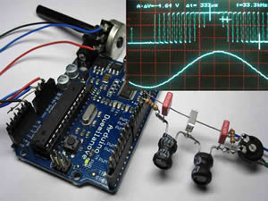
I find this circuit interesting for a number of reasons, not the least of which is its underpinning of games of chance. Beyond that, as you move down the RRRNG page, the author provides an interesting sequence of images describing how the circuit shapes the noisy, 18V source waveform into a random, but stable, 4.5 V digital waveform. This knowledge may come in handy with the direction of the Rattlesnake. The discussion then goes deeper into a discussion of weighting and storage, introducing the D flip-flop which is the model for storage used by ATMEL for its AVR line.
I put the circuit together a week ago and didn't get the expected results on my first go. I'm going back down to school today to try again. If any of you have success, please let the forum know. Jackson returned from the holidays with a working version of the circuit. Check out  Jackson Russett's RRRNG
 Timer-Based Modulation. With an understanding of the AVR's timer resources under your belt, you are in a good position to explore creative wave form generation based on these peripherals and their interrupt capabilities (an additional dividend of the effort will inform you of the role you might play in the class project next term).
Whereas audio offers a wide range of imaginative applications of wave modulation, servo motors (you've got the HXT500 Micro 9g in your kit) and other devices PWM-triggered devices can also be considered as a focus of your project. You can deepen your understanding of the Arduino Timer system by reviewing the code for their Servo library: Servo.cpp.
 Caution must be exercised when interfacing a speaker with an Arduino. Direct connection will damage the pin as an 8Ω speaker driven at 5V pulls 625 mA well in excess of the 40 mA threshold for the pin. Numerous schematics exist online to prototype this properly, typically with a low side NPN transistor and resistors at a minimum. Amplification is another consideration you may wish to undertake.
Extra time has been alotted for this project (3 weeks from today) to allow you to undertake sufficient research into the possible application that you will find stimulating and rewarding, as well as time to acquire any unique components. You might even want to discuss amongst your peers which project focus each of you could undertake that would compliment either the Rattlesnake or a paired ISP later in the year.
 This is terrific opportunity to explore your deeper interests, so give your decision considerable thought before committing.
Timer-Based Modulation Proposals as of December 6:
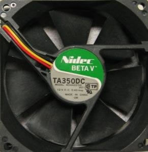
RH & JL: For our project we would like to combine Input Capture with Graphic Output. We would be utilizing the TA350DC fan, and would display its waveform on an LCD Display. I would be responsible for reading the output signal using the input capture pins on the ATmega328, and Ross would be responsible for the graphical output on the display. What we learn in this project could be used in the Rattlesnake, where either a signal is being received by the device, or the generated wave is being displayed.
CM: The idea for my project is a desk stop clock that would be made using a servo and a 3D printed face. The servo would be used to control the analog seconds of the stop clock and their would be a seven segment display that would be used to monitor the minutes. I would need to use the 3D printer to print a clock face and would need to learn how to use a design software if I can not find a good clock face that I can 3D print.
 RP: My proposal for my time / interrupt project is a metronome. This metronome would be adjustable and would be created with the timers / interrupts in mind.
JR: For this project, I want to undertake the production of musical chords using the three available timers. My goal is to be able to reliably produce the four main types of triads: Major, Minor, Diminished, and Augmented. Perhaps I will also be able to produce other types of chords, or maybe a simple harmonized song. To do all this I will need to develop code that can quickly and accurately process notes into their corresponding frequencies.
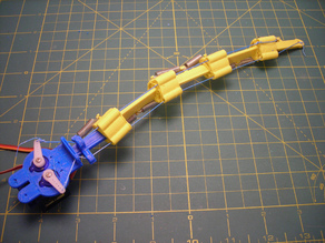
JY: For my project I want to make a finger/tentacle that is driven by two servos. This will require 3D printing STL files and assembling them with wires and springs. The arm will be controlled by 2 servos that will be driven by 2 timers. The STL files for the tentacle can be found at http://www.thingiverse.com/thing:6986 .
 External Interrupt 0.
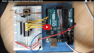
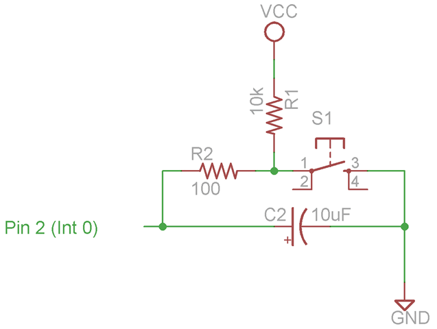
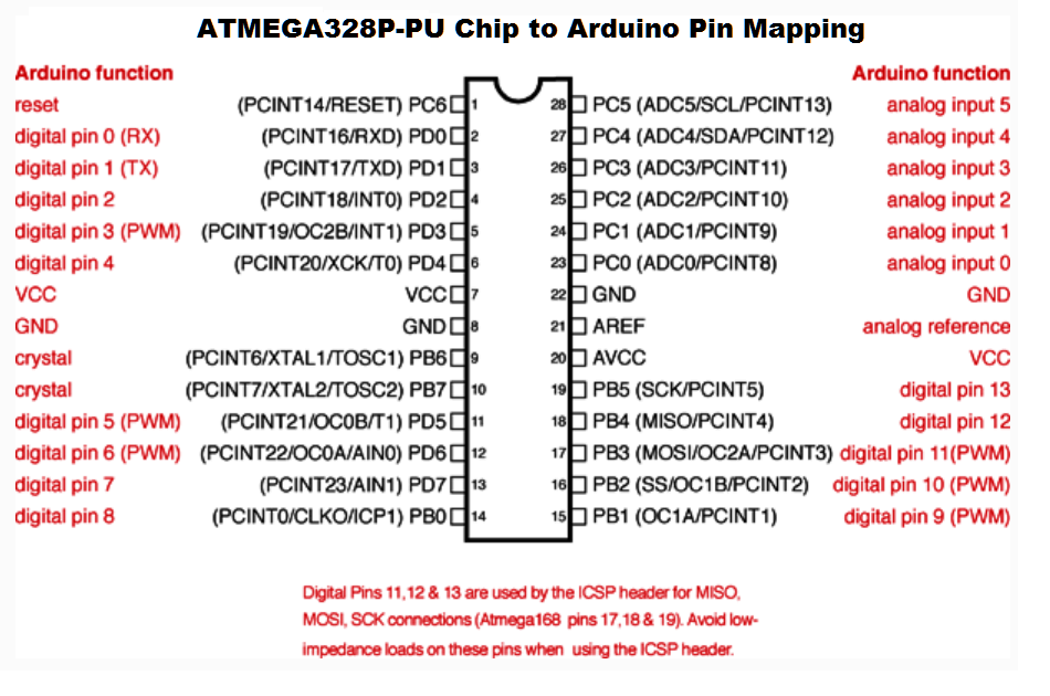
This Group Development/Individual Report project asks you to dig into the basics of External Interrupt 0 on the ATmega328P and replicate this project through modified (pure) C code to yield the result depicted in the adjacent video. You should feel free to collaborate to the extent you are comfortable, but your ER summary is expected to be highly unique.
External Interrupt 0.
This Group Development/Individual Report project asks you to dig into the basics of External Interrupt 0 on the ATmega328P and replicate this project through modified (pure) C code to yield the result depicted in the adjacent video. You should feel free to collaborate to the extent you are comfortable, but your ER summary is expected to be highly unique.
References
- Arduino Pinout
- ATmega328P Datasheet
- Google's CS4HS: Interrupts
- Interrupts and Hardware Debouncing
- Blum's Hardware Debounce Circuit (0.1μF in lieu of the 10μF seems to work fine)
- Google Images: Hardware Debounce Circuits
AVR Development Alternatives. After inserting a new page entitled TEI4M, add a new entry in your ER entitled AVR Development Alternatives. Using no less than a half a page per alternative, document the technique in detail, complete with links. Support your text and diagrams with a strategically-composed photo that includes the essential components involved.
- At the end of the writeup, indicate your preference for a particular strategy with a justification of why.
- There is no expectation for a video for this entry unless you're inspired to do so.
- Update your TOC. Get started early and use your time wisely; this is tough and there's lots to learn.
