2020-2021 ICS4U Independent Study Projects (ISPs) |
![]() Independent Study Projects. Please read our overview on why ACES pursue Independent Study Projects so vigorously.
Independent Study Projects. Please read our overview on why ACES pursue Independent Study Projects so vigorously.
 To my mind, the characteristics of a great project include such aspects as imagination, creativity, a degree of risk and, sometimes, even simplicity, to name a few. Check out the flashlight circuit 'board' this guy made out of little more that a piece of paper and a pencil? Simple, but inspiring.
Consider a problem that needs a solution. Boyan Slat did at age 17 when he was in high school; four years later he is
To my mind, the characteristics of a great project include such aspects as imagination, creativity, a degree of risk and, sometimes, even simplicity, to name a few. Check out the flashlight circuit 'board' this guy made out of little more that a piece of paper and a pencil? Simple, but inspiring.
Consider a problem that needs a solution. Boyan Slat did at age 17 when he was in high school; four years later he is Also, don't underestimate the value of an enterprise/entrepreneurial aspect to your project that could see a number of units of your project in the hands of future ACES, for sale in the Dragon's Lair or beyond, reaching an even a broader audience.
| ACE | ISP 1. (20%) Saturday September 19 |
ISP 2.(20%) Saturday January 23 |
ISP 3. (20%) Saturday April 3 |
|---|---|---|---|
Atkinson, S. |
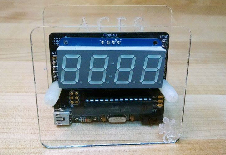
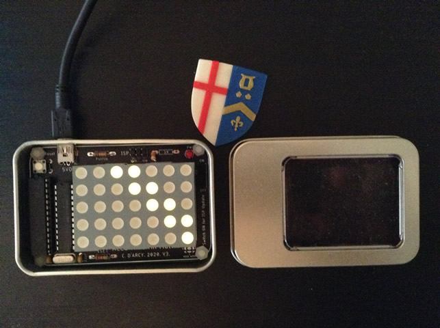
ACES' Gecko Reboot HARDWARE The ACES Gecko will take the old, outdated Gecko and create a modern version that is smaller, sleeker, and uses SMT parts. The same ATmega328p will be used but, the reboot will feature an SMT version. The ATmega328p will be programmed using working ISP headers, as well as have all the necessary conditioning resistors. The goal with the updated hardware on the Gecko is to create a smaller design that looks closer to a finished product........ SOFTWARE Arguably the most important part of the updated Gecko is a complete software update. The device will feature a new alarm feature which will require an easy to use UI for setting it. The device will also need to display various pieces of information in a sleek way...... DESIGN First, the device will feature a custom PCB. This PCB will bring all the parts together as well as bringing the device closer to the previously mentioned production quality. Next, like the old gecko, the front of the device will have a piece of acrylic allowing for users to see the display. Finally, to bring the device even closer to a production like quality either nice standoffs will be printed or a case will be printed. |
Dolgin-Atkinson Development Board HARDWARE The Dolgin-Atkinson Development Board’s hardware will be similar to the existing DDB. The device will have the necessary voltage regulating components on board to make it reliable on a battery or USB power. The development platform will also include updates to make it programmable over USB. SOFTWARE The Dolgin-Atkinson Development Board will aim to renew the existing DDP. The renewal's most promising feature will be native USB support. This means a custom bootloader will be flashed to the ATtiny84 and then the ATtiny84 will be recognized as a USB device. On top of an already existing bootloader, serial monitor support will be added over the USB. Currently, library’s that allow this exist but only work for 16 MHz crystals. These libraries will need to be adapted to support the internal 8Mhz crystal on the ATtiny84. DESIGN The Dolgin-Atkinson Development Board will have similar design to the existing DDB. The big difference will be the PCB. On the existing DDB, there are four SPI traces connected to the SPI pins on the ATtiny84 and to the ISP connector. On the renewed version, the board will only require two traces that connect to a USB port. This will allow the development board to communicate directly using UART (USI) to the computer. |
DDB V8+ DESCRIPTION The DDB V8+ will be a stable DDB V8. In the medium ISP, the DDB V8 was developed. The development platform did work but it was not entirely stable. The goal with the DDB V8+ is to take the existing DDB V8 and get it stable enough so that every ACES can use it. DESIGN The DDB V8+ will require EAGLE and JLCPCB’s manufacturing services. These two assets will be used to make the device as production ready as possible. Most notably, the new design will use the SMT ATtiny84a. This will be used so that the DDB can be tested before distribution. This will ensure that the development platform will work for everyone. COMMUNICATION The DDB V8+ will use serial for the serial monitor as well as USB for uploading to it. These two things will be used in tandem to make the uploading process as seamless as possible. The same circuit will be used as the previous DDB to allow USB and serial communication to work on the same two digital I/O pins. |
Bizzarri, P. |
EL Wire/Panel Controller/Inverter HARDWARE The hardware aspect of this project is most likely going to be the most intense part. The core of this project, building an inverter circuit, is done almost exclusively using hardware components and techniques. Building this inverter will require an understanding of comparators, MOSFETS, and a deep understanding of the relationship between AC and DC power. All of these topics fall under the hardware domain and therefore this project will require and help foster advanced hardware skills.... SOFTWARE The software aspect of this project will mostly entail the creation of various types of waveforms. Triangle, sinusoidal and square waves are all required in an inverter, and these will all be created using code and the Arduino Uno. Also, if the inverter is successfully built, software techniques will be used to control multiple inverters at once so that a user can turn on and off specific EL wires on command..... DESIGN The design aspect of this project will be the creation of a possible PCB and case for the final inverter. I will use my previous knowledge of EAGLE and CAD to construct both items, using the prusa’s to print the case. If I end up not finishing the inverter in time to create the PCB, I will also incorporate design principles in the construction of the breadboard inverter circuit (make it aesthetically pleasing and use space efficiently). |
Line-Following Robot HARDWARE The hardware aspect of this project will involve the use of sensors and ICs. These sensors will include LDRs which would determine if the robot is moving off the line. I will also include either an ATtiny 84 or an ATmega328P as the microcontroller for the project. I am leaning towards the ATmega328P because it has more timers but I will decide later on when I am deeper in the project. I will also be using a LiPo power supply as it can supply more current than a 9v battery. The mechanical side of this project will entail the use of motors and an ESC. The motors will most likely be 9v DC motors and I have yet to decide the model of ESC. One advantage of using the ESC is that I don’t have to worry about MOSFET’s, which are components that have caused me a lot of issues in previous projects. SOFTWARE For the software side of this project I will be creating code that takes inputs from the sensor and depending on them, changes the current going to the motors. In order to add a little originality and ambitiousness to this project, I plan to have the code at register level as much as I can. This will be especially challenging for the ESC as most of them come with libraries. I will need to dive into said libraries to figure out how to make my ESC work simply using my register level code. I am really excited to write code at register level as I find it super interesting. DESIGN The design aspect of this project will entail a 3D printed chassis. This will be an especially challenging aspect of the project for me as I have very little 3D printing experience. I will have to learn a lot of 3D printing techniques but I am up for the challenge. I will most likely use Fusion for this project as TinkerCAD gave me a lot of trouble on my last project. |
Pet Feeder DESCRIPTION This project will be a pet feeder system that dispenses food and water into my dog’s bowls on a regular basis. There will be LCD or OLED display with a count down until the next food dispenses. The project will use an RTC for the timing. Servo motors and water pumps will be used for dispensing food and water. DESIGN The construction of the food and water dispensing and storage systems will be the focus of the design on this project. I will most likely use a 3D printed gate attached to the servo to allow food to pass through. If all goes well, I would like to create a PCB for this project, but this will be considered a bonus for myself. This PCB would contain the MCU and attach on to the LCD or OLED screen. COMMUNICATION The communication protocol used in this project will be I2C with the RTC. Although I have used the RTC before, it will be good to get back into using this communication method as I have not used it since grade 11. MECHANICAL This project will entail Servo motors and water pumps to dispense the food. These motors will be closely intertwined with the design of this project to ensure optimal performance. |
Goldman, A. |
SMT 555 Breakout Board HARDWARE The hardware portion of this project encompasses the circuit design reflected on the PCBs. The 555 Timer, combined with external components, such as capacitors, resistors, and potentiometers, is what generates the clock signal that is desired from the breakout board. This project features multiple boards, specially designed for different RSGC ACES scenarios. One features an adjustable frequency and duty cycle with the adjustment of potentiometers, and one is very tiny for compact circuits, with a preset frequency and duty cycle. Specially designed PCBs for breadboards and the Arduino Uno ensure there is a breakout board for every potential ACES project....... SOFTWARE Various software examples demonstrate the capabilities of the different breakout boards. The visual nature of the examples helps demonstrate to ACES the uses and characteristics of the various 555 Timer signals that can be generated. These examples show what the meanings of duty cycle and frequency are, and how they can be altered by changing the components of the external circuit connected to the 555 Timer to achieve the desired clock signal characteristics...... DESIGN Design is crucial in this project. The PCBs are designed in EAGLE with the ACES program in mind. Each PCB is thoughtfully and specifically designed for different potential ACES projects. Special care is taken to ensure the layout of the PCBs are convenient for breadboarding and use with the Arduino Uno, with easy ways to use the breakout board without it consuming too much project real estate. The preset signal boards, with their tiny size, can be used in projects where space is a major concern. The use of SMT and careful design ensures that the boards are as compact as possible, without sacrificing functionality. |
Long Distance Fishing Bite Alarms HARDWARE This project is a wireless bite detection system for up to two fishing rods. When a bite is detected on either rod, the user is automatically alerted on their wireless, hand held receiver unit, informing them of which rod has a bite. The project consists of three custom designed PCBs. Each rod is fitted with a PCB that uses external components to sense bites. The third PCB is the handheld receiver unit carried by the user. Each PCB is powered by an SMT ATtiny series microcontroller and supporting SMT components. The wireless communication is done via a low level RF system that does not require the use of software libraries. The receiver unit alerts the user with both auditory and visual cues and allows them to distinguish between bites on their two rods.... SOFTWARE Each board’s ATtiny series microcontroller requires software in order for the communication system to operate. Each detection board uses software to process the bite data from the external components and communicate it to the receiver board via RF communication without the use of libraries. The receiver board receives the bite data via RF from either transmitter unit and processes it in order for it to be presented to the user via auditory and visual alerts. As much software as possible is written in low level statements, such as register level, and no software libraries are used.... DESIGN Design is a very important aspect of this project. Each PCB is designed using EAGLE and EasyEDA with the user in mind. The PCBs, especially the handheld receiver, are slim and compact for convenient use and use SMT components. Each PCB is fit in a durable, custom designed 3D printed case that keeps the PCB safe from outdoor elements. The receiver unit is designed to be held in the hand or placed in the pocket. |
Smart Soap Dispenser DESCRIPTION With hand washing becoming more and more important, the Smart Soap Dispenser makes the process easier. Soap is automatically dispensed when a hand is brought under the nozzle. The dispenser informs the user of how long they should be washing their hands for and when they can finish. To ensure soap never runs out for long, a display shows the amount of time remaining until the soap canister will be empty, using a calculation based on the usage of the device. DESIGN A custom designed EAGLE and EasyEDA PCB host the SMD ATmega328P microcontroller. The external components, such as the sensor, pump, and display, are connected to the MCU via headers or screw terminals on the PCB. The Smart Soap dispenser is housed inside a custom 3D printed case which allows for easy hand washing and removal of the soap canister for refills. COMMUNICATION The Smart Soap dispenser uses IR technology to detect if a hand is under the soap nozzle, without the need for physical contact. The display aspect of the project features the use an OLED display, using I2C communication, or a series of small seven-segment displays, making use of SPI communication between the MCU and the supporting shift registers. MECHANICAL The Smart Soap Dispenser makes use of a DC Motor pump to lift soap up from the canister and deposit it at the nozzle. The pump’s power system is kept separate from the MCU’s |
Robertson-Caryl, L. |
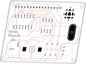
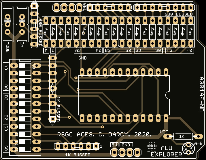
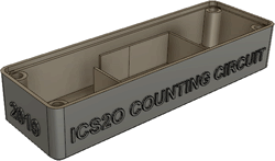
74LS181 ALU Shield HARDWARE The ALU shield is primarily a Hardware oriented project that attempts to display the logical and arithmetic capabilities of the 74LS181 ALU chip. This integrated circuit will be paired with a series of simple components to perform sixteen possible logic operations or sixteen different arithmetic operations on two 4-bit words/operands. These "words" will be inputted using switches on the device as well as the desired operation. Sixteen LEDs divided into four groups will represent the states of A operand bits, B operand bits, operation bits, and the 4-bit result of a given logical or arithmetic operation. Three separate LED's will act as indicators displaying to the user what mode the ALU is in (logic or arithmetic), how the operands compare in value (A=B), and if the result of a function is greater than 4-bits (carry output). Two switches will allow the user to toggle with the ALU's mode and carry-input. The circuit's entirety will be housed on a PCB, compatible as a shield with the Arduino UNO...... SOFTWAREThe ALU is limited in software usefulness as it provides 1970's computing to a modern microcontroller, which has inordinate arithmetic capability in comparison. However, the PCB's shield components will allow the Arduino to access the ALU's inputs and outputs. A simple program will be designed that enables a user to test the ALU's operations and view its results...... DESIGN As previously stated, the project will be housed on a PCB. The current ACES's ALU is likely to be faulty, so a new board will be designed in EAGLE to accommodate design changes and fix any wiring errors. These new design changes will revolve around making the ALU compatible with Arduino programs and pins. |
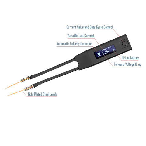
Micro-DMM HARDWARE A Micro-DMM trades complexity for size and convenience by only displaying voltage, current, and continuity on a compact I²C OLED/LCD screen. The circuit will consist of a PCB mainly occupied by surface mount parts. A five-to-one voltage divider circuit and a current measuring IC (positioned on the board) will be continuously read by an ATtinty84 (SMD). Two input ports (positive and negative) will allow the user to access the Micro-DMM's capabilities with any custom wire or cable of their choosing. SOFTWARE Software for the Micro-DMM will consist of reading analog and digital data from sensors, then translating that data into text on an LCD screen. The final software is to be accurate (multiple significant figures), fast, and produce clear results which engineering students can interpret. DESIGN A custom PCB designed with the intention of minimizing space will house the devices' circuit. Furthermore, a 3D printed case, created in Fusion, will enclose the PCB and hold the LCD screen in place.
|
Auto-Bailing Canoe DESCRIPTION. The Auto-Bailing Canoe drains the hull of a canoe automatically while the two canoeists paddle. Thus, saving time and improving the efficiency of the boat. The mechanism works by sensing the amount of water that has migrated into the canoe’s hull and then actuating a relay that turns on a marine-grade DC motor (12v). A waterproof 3D printed case will hold the batteries, microcontroller, and relay, while the sensor will be waterproofed and connected to the boat's hull. Finally, the DC pump will be discreetly positioned on the side of the canoe as to not obstruct the campers when paddling or portaging. DESIGN. Design will be the most curtail and challenging component of this project. Water-resistant 3D printer filament will be sourced along with other waterproofing materials: gaskets, rubber coating, and screws. Furthermore, Fusion 360 will be the design software of choice for improved precision (as my 3D printing skills must exceed just using tinkerCAD). The use of space will be a challenging factor to overcome as the Prusa I3 build plate has limited room for a large battery pack. COMMUNICATION. An I2C-capable water/moisture sensor will be used to detect whether water has entered the boat. Furthermore, the microcontroller will use its small voltage output to trigger a relay which will enable higher voltage to actuate the motor. When the boat is empty of water the sensor will send an I2C message to the Arduino, which in turn will trip the relay and turn off the motor. MECHANICAL. A small 12V submersible motor/pump will be sourced to pump water from the canoe’s hull back into the lake. The motor will be powered by a 12 Volt rechargeable battery positioned inside the waterproof case. The motor will be controlled by a relay module which will complete its circuit. |
Shibley, J. |
SHiB181 ALU HARDWARE Digital Logic chips are used to create a combinational logic circuitry that replicates the internal structure of the 74181 ALU chip. The internal structure of the circuit is monitored by LEDs displaying various internal and external outputs. 7400 Series ICs will be used throughout the project to maintain compatibility with the rest of the CHUMP project..... SOFTWARE While no software is directly used in this project, the combinational logic circuit will be explained in depth by breaking down the various subsections of the circuit. This will result in the explanation of various boolean functions, which can also be used in software programming..... DESIGN Once the design has been prototyped on a breadboard, it will be transferred to a printed circuit board. This board will be designed on EAGLE. This board is compatible with Liam Robertson-Caryl’s ALU Explorer and the CHUMP project. |
SHiB64 HARDWARE The SHiB64 is a custom 8-bit computer based off of the first era of personal computers from the 1980s. It incorporates numerous new and quirky ICs and will require familiarizing oneself with the hardware of the late 70s and early 80s SOFTWARE Because the computer requires the ICs to communicate with each other, I have to utilize machine code to create my own version of BASIC. DESIGN The final computer will be situate on a set of PCBs in a 3D printed case. |
SHiB Rocket Guidance System (RGS) |
Vretenar, J. |
CNC-Milled CHUMP Case HARDWARE There will not be much hardware in this project as it is mainly design... SOFTWARE There will be no programming as this is mainly design.... DESIGN I will be exploring different CNC programs and will also be designing a case/display case for the ABRA 48 breadboard which we will be building our CHUMP on. This case will be milled out of wood, and would be used as a case to hold and even help display the CHUMP that we will build. |
The Weather Matrix HARDWARE There will be a matrix made out of surface mount LEDs connected to a MCU to control them. SOFTWARE There will have to be code written for the MCU and an API will allow the MCU to read information from the internet. DESIGN This will include an Eagle PCB and a case design. Using either 3D printing and/or CNC milling. |
Bionic Hand DESCRIPTION I will be 3D printing a bionic hand that can be controlled using a glove with sensors in it. The fingers will be moved using servo motors that change in position based off of the glove fingers bending. DESIGN I will be designing and printing a hand that will hold the servo motors. I will also be using a glove with a printed circuit board for the control. DESIGN I will be designing and printing a hand that will hold the servo motors. I will also be using a glove with a printed circuit board for the control. MECHANICAL I will be using servo motors to control the fingers bending in the hand. |
Short ISP with Design
Proposal Form (Word): Short ISP Proposal with Design
 As you wind up the final two terms of your secondary education it is time to both advance and lock in your burgeoning engineering skills. Whereas through-hole technology (THT) has had a good run over the past few decades, the future is Surface Mount Technology and Design. For this reason, you best be prepared. This ISP round you will refine your SMD and CAD skills to showcase your Design skills in preparation for the opportunities that await you in the next few years.
Your Medium ISP goal (20% of your final mark) should include the slimmest of useful DES devices consisting of a custom PCB, populated with SMT parts, and encased or hosting (Truth Be Told, Mastermind) 3D printed components in the thinnest form possible (think wallet-size proportions). You have two months. Our 3D Printing TAs, and either JLCPCB or DirtyPCBs are all about to get a serious Sr. ACES workout.
Should you be stuck for a meaningful project, consider a DDPv6 Legacy Shield to complement or replace the ones we already have (Intersection, ADC, Universal v1 or Universal v2). The only stipulation I impose is that these devices must remain compatible with our current EAGLE DDPv6/Shield files.
Download and review the updated Medium ISP Proposal. This Word version I would ask that you edit, attach, and email on Saturday January 23, 2021 under the Subject Line: Medium ISP Proposal.
Long ISP (THT and/or SMT, Fixed or Flex)
Download and review the updated Long ISP Proposal. This Word version I would ask that you edit, attach, and email to on Saturday April 3, 2021 under the Subject Line: Long ISP Proposal. 
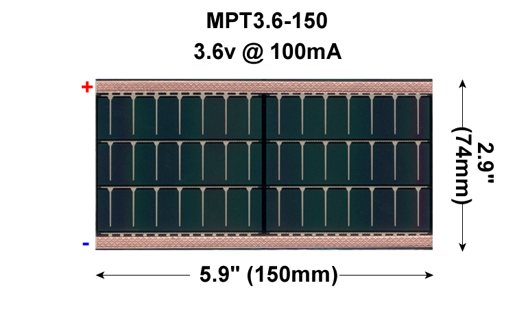
Electronic control over your final ACES ISP must be in the form of custom PCB populated with either through hole and/or surface mount components. In the case of the latter, you can consider taking your design to the next level, in the form of a Flex circuit that will be laminated into a page of your DER. If your circuit proves fully functional a flexible 3.5V, 150 mA Powerfilm solar cell will be included in the lamination so that that viewers of your creativity will marvel at when shown the light of day!
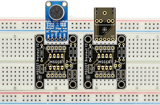
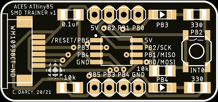
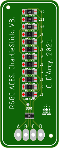
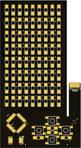
![]() The Flex Circuit concept was first introduced into the ACES curriculum in the 2015/2016 TEI4M year with some impressive results. Where the attempts since have failed is whren the designer becomes too ambitious. If you choose this route, I require that you keep it SIMPLE. (LEDs and resistors only?) Your Medium ISP requirements provided you with valuable experience that should improve your likelihood of success as will be a small project this term that requires the use of the ACES ATtiny85 SMD Trainer. The examples below are too ambitious for us but each offers a unique feature you may wish to consider,
The Flex Circuit concept was first introduced into the ACES curriculum in the 2015/2016 TEI4M year with some impressive results. Where the attempts since have failed is whren the designer becomes too ambitious. If you choose this route, I require that you keep it SIMPLE. (LEDs and resistors only?) Your Medium ISP requirements provided you with valuable experience that should improve your likelihood of success as will be a small project this term that requires the use of the ACES ATtiny85 SMD Trainer. The examples below are too ambitious for us but each offers a unique feature you may wish to consider,
| Grade | Contribution to Final Mark |
|---|---|
10 |
30% |
11 |
40% |
12 |
60% |
For the bulk of your formal education you have been, and will continue to be, required to consume curriculum chosen for you by someone else. Fortunately (hopefully) you will put this knowledge and skill to good use in your future. However, jumping through someone else's hoops alone does not, typically, secure future success. For that, you must demonstrate your own initiative, motivation, and passion. These qualities need to be cultivated and our Grade 10 hardware course is a perfect place to start. There is so much to learn and there are so many great projects out there that offer stimulating contexts within which to develop and refine your interests.


