It is difficult to overstate the importance of the onboard Timer/Counter units embedded within MCUs. So important is an understanding and competency in their Interrupt usage I have committed this separate page to exploring their configuration and application to digital signal generation.
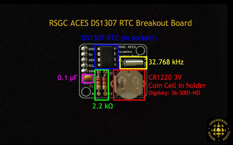
Your Grade 11 course introduced you to the DS1307 RTC, in particular, to its dependency on a 32.768 KHz crystal oscillator to keep accurate track of time by internal counter registers. As you are aware, the default source of your ATmega328P MCU clock is a 16 MHz crystal. It should be noted that alternate system clock sources are always an option. One possible motivation for doing so is the relatively awkward frequency calculations associated with the Arduino's standard 16 MHz crystal. This is, indeed, 16 000 000 oscillations per second. Since Timer/Counters are either 8 or 16-bit, and prescalers are also powers of 2, a crystal frequency that is also a power of 2 (such as the 215 or the 32768 Hz crystal used with the DS1307 would make for improved timekeeping. For this reason I have ordered a small number of the 8.192 MHz crystals from Digikey for a clock project I (or one of you for an ISP?) may like to take on.
Here's some possible inspiration for your Long ISP: How a quartz watch works - its heart beats at 32.768 kHz
Crystal Oscillators
ATmega328P Timer/Counters
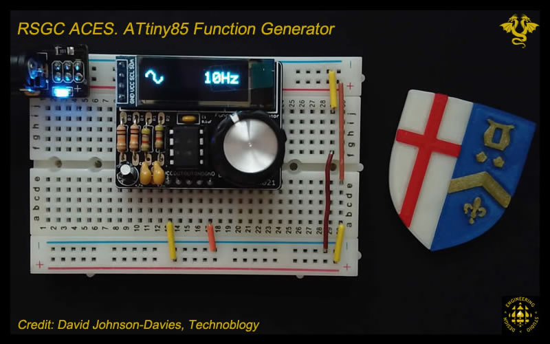
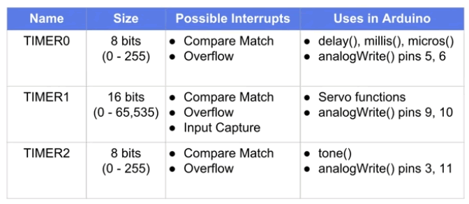
The ATmega328P has three builtin Timer/Counter units onboard (by way of contrast, the ATtiny84 has two, the ATtiny85 has one, and the ATmega2560 has SIX!) that tap into the 16 MHz crystal oscillator for sources of secondary timekeeping. These Timer/Counter units are referred to simply as Timer 0,Timer 1, and Timer 2. Timer 0 and Timer 2 are built on 8-bit counting and Timer 1 on 16-bit. Many of the basic functions Arduino users rely on invoke Timer/Counter performance in the background. To this point, the Arduino's UNO's ATmega328P leaves the factory preflashed with the Blink sketch's dependency on Timer 0, ready to rely on system clock counts to support the delay() function. (Informative) Sparkfun Video Series: Level-Up Your Arduino Code: Timer Interrupts
Associated with each Timer unit is either an 8- or 16-bit register called a counter. Under default operation, each cycle of the MCU's clock source is accumulated within the counter. When the accumulation reaches the maximum value (255 or 65535) the counter starts over again at 0. We call this an overflow event.
Understandably, with a 16 MHz crystal oscillator as the clock source, the default counter overflow frequencies are 62.5 kHz (16 MHz/256) for 8-bit counters and 244.14 Hz (16 MHz/65536) for 16-bit counters (interestingly, if you attached this signal to a speaker with sufficient amplification, humans would not hear anything with these frequencies). As mentioned, these are the default behaviours. A review of the Timer/Counter Block Diagram to the right suggests there are many options for tailoring counter behvaiour and the resulting digital signal forms that can be generated from strategic interrupt designs.
One significant option for tailoring the behaviour of the input clock signal the Timer sees is the prescaler. As previously encountered with the 128 kHz Watchdog timer oscillator, a prescaler divides the clock signal into multiples to effectively slow the input signal down. This and numerous other options, are explored below.
Interrupts #8-#17. Timer/Counter Interrupts
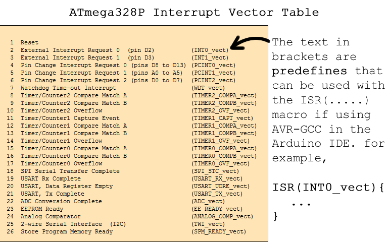
First off, another look at the ATmega328P's Vector Table below left reveals that the jump addresses #8-#17 are reserved for a number of Timer/Counter events. ACES are also encouraged to review the graphic below right to ensure they are are aware of the integration of the ATmega328P's timer in support of commonly used functionality. Overlapping uses of Timers will, understandably, result in ineffective performance. For various reasons we'll begin our Timer/Counter interrupt investigations with Timer 2, Normal Mode. Chapter 18 of the ATmega328P datasheet discusses the use of Timer/Counter 2 with details of its Register usage on page 153 of the datasheet.
ATmega328P Interrupt Vector Table
Timer/Counter-Related Uses and Applications
1. Timer2: Normal Mode (Interrupt #10: TIMER2_OVF_vect) (OC2A and OC2B Disconnected)
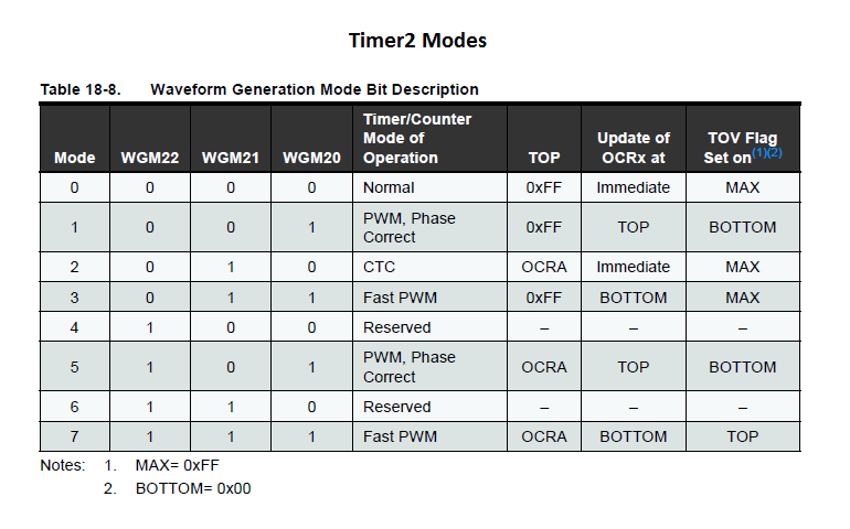
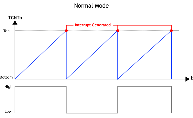
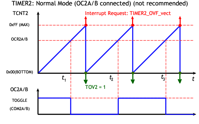
Each timer offers a slightly different set of Modes that can be configured for various purposes. The graphic below left summarizes the modes offered by Timer 2. In the simplest mode (Normal) an interrupt can be periodically generated when its 8-bit counter (TCNT2) overflows (one count after the TOP:255). The diagram below right depicts the counting as blue segments that, at their peak, trigger an interrupt as the counter simply continues from BOTTOM:0). It should be noted that all three timers offer this Normal Mode 0.
ATmega328P Timer 2 Modes
Normal Mode (0)
Task A. (No Prescaler)
The goal of this task is to create the simplest configuration of Timer2's Normal Mode resulting in an interrupt generated each time its TCNT2 register overflows. The associated ISR will inform our code that the state of the development board's onboard LED could to be toggled.
Create the Arduino project Timer2Normal and set to it. Questions to be entertained include,
To what extent should I employ my personal library (MEGA328P.h) and what assets should be added ?
What Interrupt vector is this and what is the precise syntax of the predefined that should be included as the parameter to the ISR macro ?
What is the frequency of this Overflow Interrupt? The LED ?
What is the duty cycle of the square wave driving the LED frequency ?
If a speaker or buzzer replaced the LED would we hear anything ?
What might be the simplest way to increase the overflow frequency ?
Without introducing the concept of a prescaler, what might the simplest way to decrease the LED frequency ?
Could the ATmega328P's Timer 2 act as a replacement for the DS1307 RTC ? Would this make for an interesting ISP ?
How could your Watchdog Timer Interrupt knowledge be useful for scheduling manipulation of Timer 2's Normal Mode operating conditions ?
Task B. With a Prescaler
For many (most?) applications the overflow interrupt frequency of the previous task is too high. This is where the concept of a system clock prescaler can be introduced.
Open the graphic to the right and review your options for reducing the number the MCU system clock cycles that are counted by Timer 2. (Note. Each Timer has its own unique set of prescalers)
Tab to the worksheet entitled Square Wave to Notes and review the role of the prescalers in determining the frequencies of the resultant square waves.
Tab to the worksheet entitled Frequency Formula and review the calculations required to yield specific frequencies.
Click on the graphic to the right and review Timer 2 registers.
Reopen your Arduino project Timer2NormalMode and configure the slowest Timer 2's overflow frequency using the maximum prescale possible. What is this overflow frequency?
If we continue to simply toggle the state of the LED with every overflow generated, what is the frequency of the LED?What is the simplest way to reduce the LED frequency to as close to 1 Hz as possible? Do it.
2. Timer2: Frequency Confirmation with WDT
The previous investigation began our journey into Timer-generated waveforms. Before we get too far along, it is instructive to confirm the frequency of the interrupt generation. The formula to the right is a good starting point for determining the expected overflow frequency, fovf of Normal mode where the count starts at 0 and through the intervention of a prescaler value (PVal) until it reaches the capacity of the respective Counter (255 or 65535) before triggering an interrupt.
OK, time to roll our skills forward. To assist us in monitoring the overflow frequency for a particular Timer configuration, we can employ our recently mastered Watchdog Timer interrupt to schedule and trigger the display of fovf to the Serial Monitor at periodic intervals.
Task.
Use the formula above right to determine an expected fovf for Timer 2 with a prescale value of 1024. Let's develop code to confirm our calculation.
Create an Arduino project entitled, Timer2NormalWDTOVerflowFrequencies.
Include your up-to-date Mega328P.h library that has both the full WDT and Timer prescaler constant #defines
In your setup() function configure Timer2 for Normal Mode under a prescaler of 1024 and a ISR(TIMER2_OVF_vect) to simply count overflows.
Also in setup(), configure your WDT to schedule an Interrupt (no System Reset) every 1s that triggers a boolean variable to alert the loop() function to display Timer 2's fovf
OK, how close did the empirical result from the sketch come to the expected frequency from step 1? Identify a possible set of factors that may be influencing the difference between the theoretical (<~64 Hz ) and empirical (≥ 64 Hz) frequencies.
Preload. One final option worth investigating, for any given timer/counter prescale constant, is the ability to increase the frequency by simply loading the counter with a value between 0 and the value that triggers the overflow interrupt. Using the formula above, determine the value to preload into TCNT2 within each TIMER2_OVF_vect ISR, to result in a frequency of as close to 100 Hz, as possible. Test your calculation
ATmega328P Timer 2 Normal Mode with Preload ?
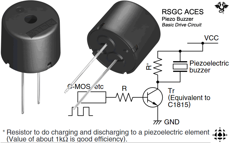
(PS1240P02BT) Piezo Buzzer Drive Circuit
3. Timer2: Normal Mode (Interrupt #10: TIMER2_OVF_vect) (OC2A and OC2B Connected)
In the two previous tasks, we exploited Timer 2 hardware to signal our software to maintain the square wave driving an LED. As I stated early in AVR Optimization #2,
"The most efficient software for the embedded developer is typically none at all".
In this next task, we'll use hardware alone to produce the square wave driving the frequency of the LED.
ATmega328P Timer/Counter Output Compare Pins
Timer 2 Normal Mode (OC2A/B connected)
A closer look at the pin mapping of the Arduino below left reveals 6 digital pins with alternate functionality labeled OCnX (pins 3,5,6,9,10,& 11). These pins can be configured to change their state (cleared, set, or toggled) when a Timer/Counter register such as TCNT2, matches the value preloaded into either of it Output Compare Registers (OCR2A or OCR2B). Since this functionality is achieved strictly at the hardware level (software ISR not required) it offers improved efficiency.
Task.
Save your Timer2Normal project as a new project entitled Timer2NormalOutputCompare.
Remember, developing great code is always in play. Take your time, now, and consider adding new, reusable assets to your personal Mega328P.h library as these tasks are undertaken so that they're available in the future.
Span a bicolor LED across on pin 11 (OC2A) and pin 3 (OC2B), as shown to the right, setting the respective DDRs for output.
Configure PB3 to present a ground for the time being.
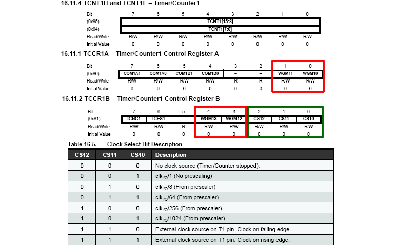
Configure Timer 2 to produce a square wave on pin 11 (OC2A) , at the lowest possible frequency, in hardware alone (no ISRs required!). The following registers deserve your consideration,
TCCR2A: WGM?, COM2s (see below left)?
TCCR2B: WGM?
OCR2A: value?
TIMSK2: OVF enables?
What is the lowest possible LED frequency achievable using this strategy?
How sensitive is the LED frequency to the value stored in the OC2RA register?
An enjoyable exercise is to display Timer/Counter behaviour in the Arduino Serial Plotter. In the plot below left, the baud rate was cranked up to 2000000 to track the value in Timer 2's TCNT2 register. This gives you some confirmation that the 8-bit counter is working.
An interesting variation on this code would be to put pin 3 (OC2B) to work as well. Modify your code to present the bicolor LED sequence RED-off-GREEN-off-RED-off-..., continuously, in equal intervals.
Examine and interpret the plot below right with respect to the phase shift of the OC2A and OC2B signals compared to a ISR(TIMER2_OVF_vect) signal monitored with a toggled state variable.
Timer 2 Normal Mode (TCNT2)
Timer 2 Normal Mode (OC2A, OC2B, and OVF Signals)
??
4. Timer2: Normal Mode, Interrupt #8 (TIMER2_COMPA_vect) and Interrupt #9 (TIMER2_COMPB_vect)
The previous task bypassed software altogether in presenting matches between TCNT2 and OCR2A and OCR2B as 50% duty cycle square waves, with a limited range of frequencies, to digital IO pins 11 (OC2A) and 3 (OC2B), respectively. Although independent hardware performance is often desirable, there are application where synchronous software intervention would be desirable.
Another look at the 328P's IVT below left, reveals a pair of additional interrupt vector addresses, conveniently, for all three timers. In this next exercise you are asked to piggyback on the previous task to perform an audio frequency task.
ATmega328P Interrupt Vector Table
Timer/Counter-Related Uses and Applications
Task.
Check out this Online Online Pitch Detector. I would like to predict/experiment/confirm that we can develop a crude register-level simulation of what the Tone library achieves.
Attach your buzzer so that pin 8 supplies the drive signal to the buzzer. Not all buzzers and created equal. Some require a fixed DC voltage, some require a square wave to move drive the diaphragm, some required external components for amplification, etc. so be prepared to engineer!
Open your previous Timer2OutputCompare sketch and save it as as ToneTests.
Click on the Timer2 Register Summary image, below, left, and examine the additional Enable bits in the TIMSK2 register rom the previous task and add the required code to trigger a software interrupt #8, TIMER2_COMPA_vect.
Possibly with our Timers.xlsx workbook as a guide, see how close you code can be developed to produce a desired frequency and have the Online Pitch Detector confirm your calculations.
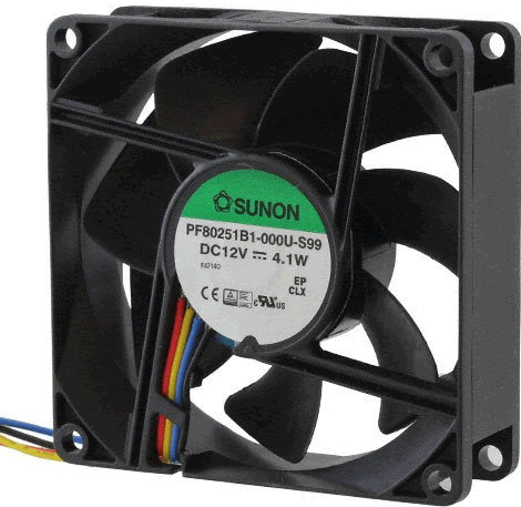
40. [2017/2018] THE 4-WIRE DC FAN.Researching and developing this project has been extremely rewarding and it is a superb context for assembling and reviewing much of the engineering content we have explored over the past two and a half years.Furthermore, this project requires the use of all three timers available on the Arduino!
Few components are available in a greater variety than the humble DC Cooling Fan. The 4-wire Sunon 12VDC ball bearing fan was chosen for this project because it offers numerous options that can be explored under elementary and advanced microcontroller operation.
PART A. GETTING ACQUAINTED WITH THIS FAN
Look over its datasheet and familiarize yourself with as many of its characteristics as you can.
Here are some questions you should be able to answer if you've read the two pdfs thoroughly,
What is the typical operating voltage and current draw of this fan?
Identify the name, colour and function of each of the four wires.
What is the operating voltage range of the PWM signal?
What is the recommended frequency range of the fan's PWM signal?
What operating conditions produce a detectable audio hum emanating from the fan and how can it be eliminated?
What is the frequency of the Arduino's PWM signal from it's analogWrite() function? Explain why.
Can the Arduino handle the Fan's PWM requirements 'easily'? If not, what course of action must be considered?
What is meant be the term open collector (aka open drain)? To which wire colour does this pertain and what additional component is required to facilitate the correct performance of this function?
What is the FREQUENCY:ROTATION ratio of the output sense wire?
Identify the direction of airflow and fan rotation from the arrows on the housing before taping the index card and paperclip to monitor the action of the fan.
PART B. HARDWARE DESIGN. The web has a great deal of instructional content for interfacing 2- and 3-wire fans. For 4-wire fans there is a far less and some if it is inefficiently designed or simply wrong.
With all the knowledge gained from the previous stage, develop an (initial) Fritzing diagram that includes a 12V source to power the fan and a 5V source for the Arduino logic. Someone has created a Fritzing image of a 2-wire fan to make the diagram (somewhat) more realistic. Here's an explanation of how to add new parts to Fritzing.
PART C. PWM DESIGN. PWM signal design (modulation) requires consideration of two characteristics: frequency and duty cycle. Our (fun) challenge is to configure an AVR timer to provide a PWM signal to match the optimal requirements outlined in fan's datasheet. Whereas the frequency of the signal remains constant, the duty cycle (speed) should be variable (in this stage, we'll hard code the changes to the duty cycle. In the next stage we'll consider external control (manual or sensor) over the duty cycle). Finally, as you develop your solution, remember, the best (most efficient) strategy places as much, if not all, the burden on the hardware that can perform in the background.
T. Morland (RSGC '18) developed a working solution after class Wednesday and offers us this scope trace of his assembly implementation ...
PART C Task.
MaxEmbedded offers one of the web's most straightforward overviews of AVR Timers, in my opinion, if you need it. (Hint: You'll find this discussion applicable to this project in more ways that one :)
The author of the AVR Timers article says, "With a clock frequency of 32 kHz and 8-bit counter, the maximum delay possible is of 8 ms." Explain this, as simply as possible, using powers of 2.
Review Ken Shirriff's Secrets of Arduino PWM blog for some extremely informative background.
From what you know of this fan's preferred PWM frequency and our requirement for a variable duty cycle, suggest the optimal WGM for controlling the device.
After deciding on the respective Timer to use (Timer0, Timer1, or Timer2) work out the complete set of register values to create the signal you chose in Step 2.
PART D. Fan Speed (ADC). We've reached the stage in this project where the speed of the fan (duty cycle) is turned over to the operator. For this, we need to explore low-level register manipulation of the AVR's ADC unit.
I have assembled a summary of the applicable ADC Registers (below) from Chapter 24 of the ATmega328P datasheet. After reviewing the recommended ADC example, implement the code necessary to have your pot, acting as a voltage divider, control the speed of your fan by reading the sweep leg (C) on Analog pin 0. Upload your code and test. The fan's speed should be responsive to your turning of the pot.
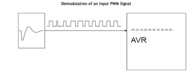
PART E. SENSE (FEEDBACK, TACHOMETRY, YELLOW) WIRE (Demodulation of PART C's PWM).
OPEN loop systems (no feedback) are undesirable as the user has no idea if the process is functioning as designed.
CLOSED loop devices such as our 4-wire fan offer a means of monitoring and adjusting our input PWM by sensing the speed of rotation and placing this signal on the fourth (yellow) wire. This variable PWM signal can be captured and demodulated by our microcontroller, analyzed and the data used to adjust the input PWM as necessary to ensure the fan is maintaining a desired performance. Note. All sorts of information can be carried by a PWM signal. An image from the datasheet you are about to read suggests how the duty cycle of a PWM signal could be used to carry ASCII data. Inspiring stuff.
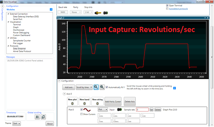
The 328P's Timer1 facilitates the capture of the yellow wire's PWM signal through it's ICP1 function (mapped to Arduino's digital pin 8). Demodulation of this signal will expose the fan's actual RPM. Furthermore, through Atmel Studio's Data Visualizer feature we can explore AVR's Serial Communication feature and plot both the theoretical and actual RPM. This sets us up well for the final stage of this project, PART F: PID.
PART E. Task (TACH Wire Demodulation)
Software Design Considerations. The goal of this stage is to begin the process of confirming the claim on page 11 of the fan's datasheet with respect to the input duty cycle vs the RPM of the fan. A screen capture of the graph appears to the right for your convenience. Just like Ken Shirrif, Nick Gammon has posted some highly respected insights into AVR programming. Check out his Timers and Counters Blog searching for, Timing an interval using the input capture unit when you get there. This will give you some useful insights.
What Arduino pin maps to the Input Capture facility of the ATmega328P?
Add the function T1Init to the project and call it immediately following rcall T0Init. Timer 1 is resonsible for two interrupt sources: Input Capture and Timer Overflow. With the provided links and the Register references above, implement Timer1's Input Capture feature based on the falling edge of the signal provided by the fan's Tach wire. Within the TIM1_CAPT ISR, simply increment a register with every interrupt.
We intend to publish the monitored RPM every second. So, configure Timer1 to overflow every second.
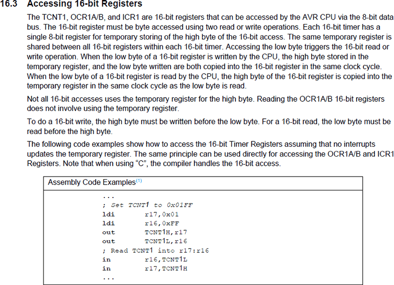
PART F. Serial Communication (USART: Universal Synchronous/Asynchronous serial Receive and Transmit) After all the groundwork previously laid we're now in the enviable position of acquiring data from our system and placing it into serial data stream for external retrieval.
In this stage we're going to confirm and display as text, the value of OC2B and number of falling edges the tach wire is yielding per second.
Just as the Serial Monitor and Serial Plotter are available tools within the Arduino IDE, Atmel Studio offer a far more comprehensive utlity, the Data Visualizer, that does a great deal more. To fully exploit its capabilities we must learn to navigate the AVR's USART subsystem.
Add the function USARTInit to the project and call it immediately following rcall T1Init. In this function we need to set the Baud Rate Register (UBBR0H:L), enable the transmit capability (TXEN bit) and declare the Character SiZe (UCSZnn bits) to be 8.
Return to your ADC_Conv_Capt ISR and let's set the the duty cycle, correctly. You see, the value obtained from the ADCH must be mapped to a value between 0 and OC2A (80) to be accurate. The good news is that this turns out to be easier than you might think!
Within your TIM1_OVF ISR place the OC2B values on the serial commmunication channel. These values should range over the interval [0,80]. Offset the values read by 32 to avoid the range of ASCII control codes.
Next, place the count of the number of pulses per second captured in the input capture pin. These values should range in lock step with your OC2B values and range over the interval [30,170] corresponding to the RPM interval, [900,5100].
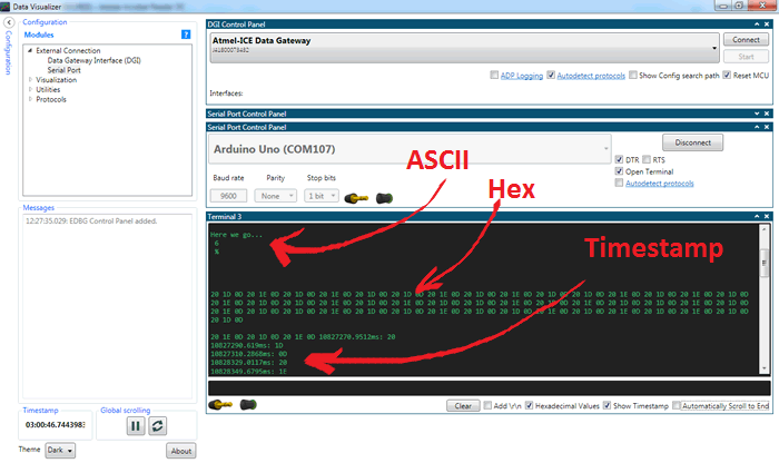
Launch the Data Visualizer, open the Terminal Window and confirm the data stream. You might with to add a Return to each line of the stream. How do you think you do this? It might easier to interpet the values in hexadecimal rather than their ASCII interpretations.
PART G. Graphic Data Visualization. In this stage we wish to generate a graphic plot comparing the theoretical RPM to the empirical RPM obtained through feedback, setting the stage for the final leg of ths [epic 8-part] marathon: PID in which we expect to the exteced and actual plots to merge. A plot of the Duty Cycle, Theoretical RPM and Empirical RPM are displayed over a FULL range of input duty cycles provided by a potentiometer was undertaken weeks ago in the high-level Arduino IDE and visualized by it's Serial Plotter utility over 1 s intervals. in this stage we'll see to what extent we can produce a similar visualization through AVR assembly exploiting Atmel Studio's Data Visualizer.
Arduino Serial Plotter
Atmel Studio 6 Data Visualizer
PART G. Task.
The first modification to our stated goal will be to scale RPM, back to RPS (theoretical and empirical). Duplicate your RPM array to a new RPS array and reduce each of the elements by a factor of 30. (Note. While it might appear that we should reduce RPM by a factor of 60 to achieve RPS, since the tach wire reports two falling edges per rotation, we save ourselves an extra division by 2 (bit-shift right one) if we use 30 as the reduction factor)
As of the day of creating this exercise, I have not discovered a simple strategy to have two plots appear on the same graph. Until I do, I recommend placing only the difference between the theoretical and empirical results leading to an ideal range of 0.
Within your Timer1 Overflow ISR (TIM1_OVF) immediately move the (empirical) pulseCount into a register and reset pulseCount to 0 (so as not to miss any half-rotations). Next, map the duty cycle to the index of theoretical RPS array (bit-shifting again should do the trick!) and obtain the element within the vector. Now, we have two issues: the difference could be negative, and the terminal window would treat a value less than 32 as a control code. I suggest we add an offset, say 65 ('A') which become the ideal target.
At the end of the TIM1_OVF ISR, load the desired value into txByte and call the transmit function.
Launch the Data Visualizer. Click on Configuration in the top left corner. Pressing the Help button, , will access context-sensitive support. Under External Connections, double-click Serial Port to launch the Serial Port Control Panel. Click Connect to see the Terminal window. Confirm the data stream.
Return to the Configuration tree in the top left corner and select Graph under the Visualization header. To plot your serial stream, drag the RCA plug from the top of the Serial Port Control Panel to the plot area. Confirm.
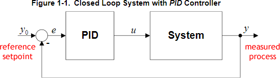
PART H. PID. You are well-aware that simply supplying a device with a required signal is not sufficient to GUARANTEE required performance. To achieve this you must create a closed loop that continually measures the process output (actual device performance) and dynamically adjusts the setpoint signal by reducing or eliminating the variance (error-e).
38. Timer1. Fast PWM Mode 15. In this exercise you are asked to develop standalone assembly code that will result in the the horn of your HXT500 standard servo motor sweeping through its 180ˆ of rotation, continuously.
37. USART Debugging Utility. In this exercise you are asked to develop a utility that can be used to debug your assembly code by dumping the contents of SRAM the Serial Monitor.
Task.
Open the file to obtain the driver code for the SerialCommunicationTestAssembly Project we started to develop last class. Do not modify this code.
Create a project by the same name and drop the code into a .ino file by the same name.
Add the partially-completed file SerialComm.S linked from our course page to this project and begin to develop the list of functions from the UML diagram on the first page of the handout.
Add the file ASCII.h fto a folder by the name (ASCII) in the libraries folder of your Arduino projects folder. Feel free to add more entries...
Using a diminishing set of comment brackets (/*..*/) implement the required functions within SErialComm.h to suppoet the project driver.
36. Timer1. Clear Timer on Compare Match. Modes 4 (Output Compare) and 12 (Input Capture) result in the TCNTn clearing (0) when it matches the preset OCRnA/B register. The attached pins can be cleared, set or toggled. This is somewhat easier to use than setting the start count less than the TCNTn resolution an climbing all the way to the overflow. The
OCRnA/B register can be manipulated in the COMPA/B ISR to modify the resulting PWM Signal.
Task.
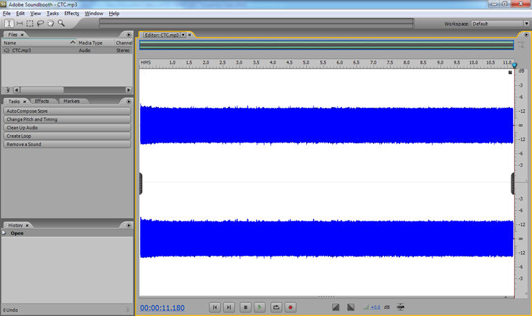
Listen to the audio file below recorded on Pin 9 under both the Timer1Clear Timer on Compare Overflow Hardware and Software Interrupts. Over this stretch, again, the volume remains constant but the pitch decreases.
The mono waveform, recorded in stereo, is shown to the right as it appears in Adobe's SoundBooth.
Review this MaxEmbedded blog for a pretty thorough explanation of the CTC Mode.
Create the Arduino project, Timer1CTC. Add the define file, prescales.h to the project if you wish.
Develop the standalone assembly code for Timer1CTC.Sthat recreates this audio file.
35. Timer1. Normal Mode with Output Compare (Software and Hardware Interrupts). In addition to a strictly hardware output response to the occurrence of a Compare event, on A and/or B, one can add a software response as well.
Task.
In addition to the configuration steps undertaken in the previous Exercise, to enable a Timer 1 Compare event software interrupt in parallel with the hardware interrupt, you need to set the OCIE1A/B flag of the TIMSK1 Register.
The syntax for the Compare Event ISR on A is a follows,
	.global TIMER1_COMPA_vect
	TIMER1_COMPA_vect:
 		...
  	reti
Modify either of the previous exercises that will result in an LED on pin 7 flashing at a quarter of the frequency of Pin 9.
33b. Light It Up! (This should be fun:) Each of you has been given a Piezo Buzzer with which we'll attempt to crank up the audio in the DES confirming each of the 7 frequency bands of the MSGEQ7 used in Ethan's Equalizer at the front of the room.
Day 1. The Arduino tone() function
Review the Arduino tone() function, in particular, it's use of the 8-bit Timer2 peripheral. Questions: Which pins can be used for the tone() function? Which pins on the Arduino are mapped to Timer2?
Create an Arduino IDE project Timer2ToneFunction and drop in the driver code, Timer2ToneFunction.ino.
Review the code and it's resources. As you can see the body of the loop() function is empty. Run the code and open the Serial Monitor noting the default contents of the important Timer2 registers.
Add statements that will invoke the tone() function on piezoPin to generate a tone of 63Hz (MSGEQ7's lowest band) and hold the note for 2500 ms, before caling the registers() function a second time to see the effect of the call and then entering an infinite, do-nothing loop. Question: Did the left band of the DES Equalizer at the front of the room respond accordingly to the 63Hz signal?Yes? Great! No?Hmmmm...
Compare the contents of Timer2's registers with values suggested by the online AVR Timer Calculator. By doing so, we can begin to trust the Calculator to produce the results needed for Day 2 of this exercise.
Finally, comment out both calls to the registers() function and insert a call to the plot() function after the call to tone(). Run the code and open the Serial Plotter.
Day 2. AVR Assembly Equivalent: Time2ToneFunction.asm
Open AS7 and create an AVR Assembler project by the same name as Day 1's high level project, Timer2ToneFunction. I recommend adding the prescalers.h header file to the root folderof the project to access prefined constants for clock prescalers for all three ATmega328 Timers.
Develop the assembly language equivalent of the high-level code to prpduce the identical 63Hz signal on pin 11.
Use the AVR Timer Calculator, to determine optimum regsiters values to produce each of the remaining 6 frequencies of MSGEQ7 (160Hz, 400Hz, 1kHz, 2.5kHz, 6.25kHz, 16kHz)
33a. Sound: Timer2 Normal Mode with PreLoad. In the previous exercise you simply let the Timer's counter run freely, restarting at 0x00 on the overflow. In this exercise you are asked to undertake an audio exploration of Timer2's Overflow Interrupt (in Normal Mode) while manipulating the TCNT2 register.
In this exercise you are asked to toggle Pin 13 with Timer2 Interrupt Overflows so as to recreate the provided audio file.
Task.
Listen to the audio file below I recorded from Timer2 Overflow Interrupts. Over the four captured overflow periods, you'll appreciate that the volume remains relatively stable while the frequency (pitch) increases. The mono waveform, recorded in stereo, is shown below right as it appear in Adobe's SoundBooth.
Review this guy's Arduino 'blag' to reacquaint yourself with mid-level Timer2 Interrupt coding. I'm calling C code 'mid-level' if it employs direct and maximum reference to the ATmega328P's registers.
Create the Arduino project, Timer2OverflowWthPreload. Download and add the (minor) updated define file, prescales.h to the project.
Develop the mid-level sketch Timer2OverflowWithPreload.ino.
With the mid-level version working, use this as a base from which to write the standalone assembly version, Timer2OverflowWthPreload.S.
32. Timers as Audio Frequency Generators.AnalogWrite PWM and the tone()Function.
AnalogWrite PWM
We have put the 6 Arduino PWM pins to good use in the past to affect the duty cycle of our signals but not the frequency. The frequency remained beyond the scope of the analogWrite(pin,dutyCycle) function.
From the previous link we find that although the 6 pins offer two different default frequencies (~490 & 980 Hz), both fall within the range of frequencies of the human ear (20Hz to 20KHz). So, let's listen and analyze to the range of the default frequencies of the 6 PWM pins to confirm...
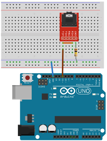
Assemble the prototype depicted to the right. The volume output from pin 11 (brown wire) is reduced by the current limiting 100kΩ resistor to ground (reduce it to 47kΩ if you'd like it a little louder). Tie the left (TIP) and right (RNG) leads of the 3.5mm audio jack breakout board together with a jumper wire (mono).
(Arduino High Level) Create the project, AnalogWriteAudio, that includes the following high-level fragment,
You will recall that the parameter to the analogWrite() function affects the duty cycle (mark/space ratio). Frequency and volume are the two primary audio characteristics you'll experience. Which of the two are affectd by the changing parameter?Does this make sense?
Move the brown wire to pin 3, modify the code and run the sketch again. Confirm that it sounds the same.
As can be seen from the Arduino's pin diagram, pins 3 and 11 are built on Timer2. It stands to reason that sf we change the prescalar for Timer2 by modifying the values in the TCCR2A register (p.156) we should be able to affect the frequency and hear the audio results. There are 7 useful prescalar values (1,8,32,64,128,256,1024). By adding and modifying the statement TCCR2B = 1<<CS22 | 1<<CS21 | 1<<CS20; confirm by experimentation which prescalar the core analogWrite function uses.
Download the Excel workbook Timers.xlsx and confirm the calculations that yield the default frequency of approximately 490Hz.
Many good high-level theory and practical references discussing the Arduino's tone() function exist and here is one of them. We'll see. In this exercise we're going to undertake a low level exploration of tone generation and listen to the waveforms capable of being generated in Normal Mode from the various timers on the ATmega328P.
(AVR Assembly) Add the file prescales.h to the project. This file contains all the convenient defines for the prescale values for each of the three Timers on the ATmega328P. Look over the contents of this file.
Download the Excel file, SoundNormalMode.xlsx. You task is to complete each entry in the table and confirm each by listening to the output of the assembly sketch below.
Comment out the high-level code above. Develop the pure assembly code SoundNormalMode.S that is equivalent (not identical) to the high-level code in Step 2 that uses a Timer1 Overflow Interrupt, with no prescaling, TCNT1H:L starting from 0, to toggle pin 13. (Note that pin 13 is not a designated PWM pin!) Plug your headphones into the audio breakout board and consider what you're hearing. Identify the frequency of this signal and make your enties in the worksheet.
Run through the code several more times, changing only the prescale constant and confirm to yourself what your hearing and the frequency. Review this frequency table of notes I believe we examined last year and is included in a tble within your Excel worksheet.
While remaining in Timer 1's Normal Mode, modify your code to get through (and listen to) all the available prescalers. Update your worksheet.
Timer0 and Timer2 are both 8-bit timer/counters. Switch to a Timer2 implematation and confirm you can generate their notes/frequencies.
Once the Excel worksheet is complete, inpsired students are invited to sample their waveforms on the oscilloscope.
31. Timer1. Normal Mode. The simplest of Timer1 modes results in the system clock incrementing its 16-bit register pair TCNT1H:TCNT1L with every tick. At 16MHz (`2^24`), the count will reach the top (`2^16`), 256 times per second. The use of one of the prescalers can slow the accumulation down.
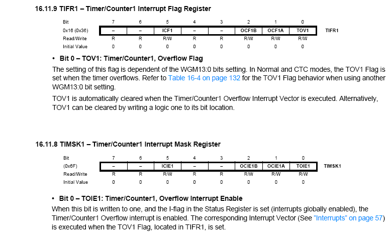
When the count overflows, an interrupt overflow (TIMER1_OVF_vect) is generated and the count continues from 0x0000 whether you service the request or not. Setting the TOIE1 bit in the TIMSK1 register allows your code to respond to the request.
Review the document, Timer1InterruptNormalMode.docx. I have provided both a mid-level implementation of a Timer1 Normal Mode Overflow Interrupt Routine to ease you into the register configurations, followed by the equivalent low-level standalone assembly version in which the ISR toggles an LED on PB5 (digital pin 13 on the Arduino) at rate of 60Hz (120 ovf/s). (Note: although 24Hz is the understood threshold for Persistence of Vision I found this far too low. Even at 40Hz, flicker is detectable. 50-60Hz is more like it)
Task.
Create an Arduino project entitled Timer1InterruptNormalMode and add the file, Timer1Interrupt1NormalMode.S. Be sure to leave the high-level file Timer1InterruptNormalMode.ino blank. Note: For future reference, you may wish to copy the mid-level version from the document and paste it in as the .ino version, as long as it is completely commented out.
Review the assembly code.
Insert an LED to pin 13 and upload the code, noting the 60Hz flash rate of the LED.
Modify the hi and lo defines that load the TCNT1H:TCNT1L register pair with values appearing in the comments, and/or try your own. to adjust the overflow frequency.
 This page is best engaged after completing both,
 It is difficult to overstate the importance of the onboard Timer/Counter units embedded within MCUs. So important is an understanding and competency in their Interrupt usage I have committed this separate page to exploring their configuration and application to digital signal generation.
 Your Grade 11 course introduced you to the DS1307 RTC, in particular, to its dependency on a 32.768 KHz crystal oscillator to keep accurate track of time by internal counter registers. As you are aware, the default source of your ATmega328P MCU clock is a 16 MHz crystal. It should be noted that alternate system clock sources are always an option. One possible motivation for doing so is the relatively awkward frequency calculations associated with the Arduino's standard 16 MHz crystal. This is, indeed, 16 000 000 oscillations per second. Since Timer/Counters are either 8 or 16-bit, and prescalers are also powers of 2, a crystal frequency that is also a power of 2 (such as the 215 or the 32768 Hz crystal used with the DS1307 would make for improved timekeeping. For this reason I have ordered a small number of the 8.192 MHz crystals from Digikey for a clock project I (or one of you for an ISP?) may like to take on.
Here's some possible inspiration for your Long ISP:
Your Grade 11 course introduced you to the DS1307 RTC, in particular, to its dependency on a 32.768 KHz crystal oscillator to keep accurate track of time by internal counter registers. As you are aware, the default source of your ATmega328P MCU clock is a 16 MHz crystal. It should be noted that alternate system clock sources are always an option. One possible motivation for doing so is the relatively awkward frequency calculations associated with the Arduino's standard 16 MHz crystal. This is, indeed, 16 000 000 oscillations per second. Since Timer/Counters are either 8 or 16-bit, and prescalers are also powers of 2, a crystal frequency that is also a power of 2 (such as the 215 or the 32768 Hz crystal used with the DS1307 would make for improved timekeeping. For this reason I have ordered a small number of the 8.192 MHz crystals from Digikey for a clock project I (or one of you for an ISP?) may like to take on.
Here's some possible inspiration for your Long ISP: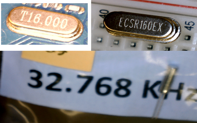

 The ATmega328P has three builtin Timer/Counter units onboard (by way of contrast, the ATtiny84 has two, the ATtiny85 has one, and the ATmega2560 has SIX!) that tap into the 16 MHz crystal oscillator for sources of secondary timekeeping. These Timer/Counter units are referred to simply as Timer 0, Timer 1, and Timer 2. Timer 0 and Timer 2 are built on 8-bit counting and Timer 1 on 16-bit. Many of the basic functions Arduino users rely on invoke Timer/Counter performance in the background. To this point, the Arduino's UNO's ATmega328P leaves the factory preflashed with the Blink sketch's dependency on Timer 0, ready to rely on system clock counts to support the delay() function.
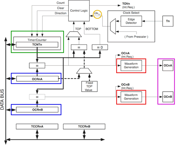
 The goal of this task is to create the simplest configuration of Timer2's Normal Mode resulting in an interrupt generated each time its TCNT2 register overflows. The associated ISR will inform our code that the state of the development board's onboard LED could to be toggled.
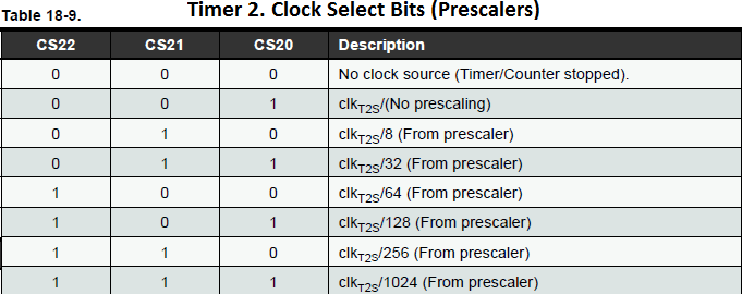 For many (most?) applications the overflow interrupt frequency of the previous task is too high. This is where the concept of a system clock prescaler can be introduced.
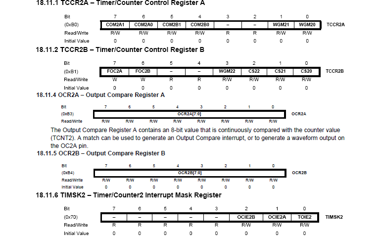 Tab to the worksheet entitled Frequency Formula and review the calculations required to yield specific frequencies.
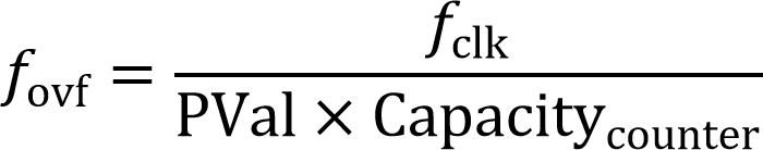 The previous investigation began our journey into Timer-generated waveforms. Before we get too far along, it is instructive to confirm the frequency of the interrupt generation. The formula to the right is a good starting point for determining the expected overflow frequency, fovf of Normal mode where the count starts at 0 and through the intervention of a prescaler value (PVal) until it reaches the capacity of the respective Counter (255 or 65535) before triggering an interrupt.
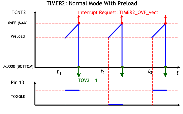 In your setup() function configure Timer2 for Normal Mode under a prescaler of 1024 and a ISR(TIMER2_OVF_vect) to simply count overflows.
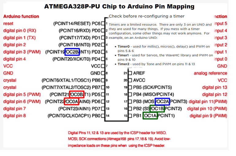
 A closer look at the pin mapping of the Arduino below left reveals 6 digital pins with alternate functionality labeled OCnX (pins 3,5,6,9,10,& 11). These pins can be configured to change their state (cleared, set, or toggled) when a Timer/Counter register such as TCNT2, matches the value preloaded into either of it Output Compare Registers (OCR2A or OCR2B). Since this functionality is achieved strictly at the hardware level (software ISR not required) it offers improved efficiency.
 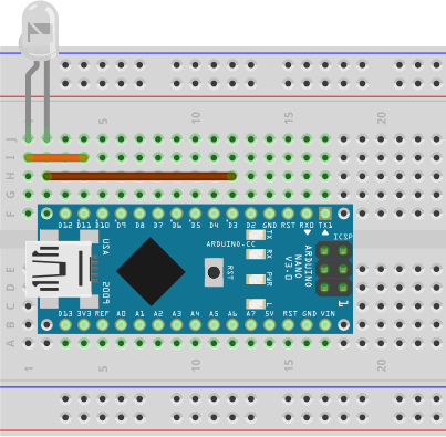 Configure PB3 to present a ground for the time being.

 PART C. PWM DESIGN. PWM signal design (modulation) requires consideration of two characteristics: frequency and duty cycle. Our (fun) challenge is to configure an AVR timer to provide a PWM signal to match the optimal requirements outlined in fan's datasheet. Whereas the frequency of the signal remains constant, the duty cycle (speed) should be variable (in this stage, we'll hard code the changes to the duty cycle. In the next stage we'll consider external control (manual or sensor) over the duty cycle). Finally, as you develop your solution, remember, the best (most efficient) strategy places as much, if not all, the burden on the hardware that can perform in the background.
 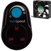 PART D. Fan Speed (ADC). We've reached the stage in this project where the speed of the fan (duty cycle) is turned over to the operator. For this, we need to explore low-level register manipulation of the AVR's ADC unit.


 PART E. Task (TACH Wire Demodulation)
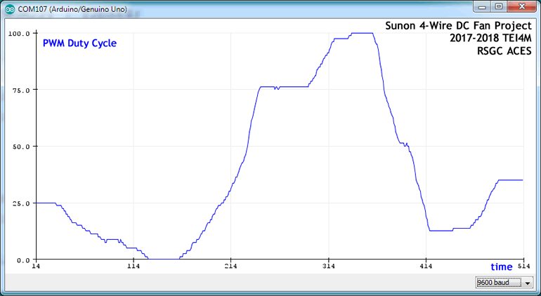 PART F. Serial Communication (USART: Universal Synchronous/Asynchronous serial Receive and Transmit) After all the groundwork previously laid we're now in the enviable position of acquiring data from our system and placing it into serial data stream for external retrieval.
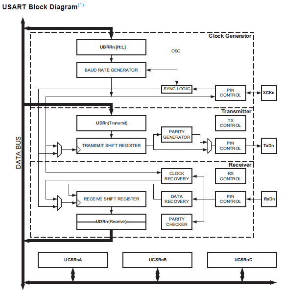

 38.
38.  decreases.
The mono waveform, recorded in stereo, is shown to the right as it appears in Adobe's SoundBooth.
decreases.
The mono waveform, recorded in stereo, is shown to the right as it appears in Adobe's SoundBooth.
 33b.
33b. 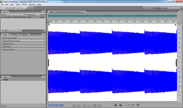 the volume remains relatively stable while the frequency (pitch) increases. The mono waveform, recorded in stereo, is shown below right as it appear in Adobe's SoundBooth.
 We have put the 6 Arduino PWM pins to good use in the past to affect the duty cycle of our signals but not the frequency. The frequency remained beyond the scope of the analogWrite(pin,dutyCycle) function.
 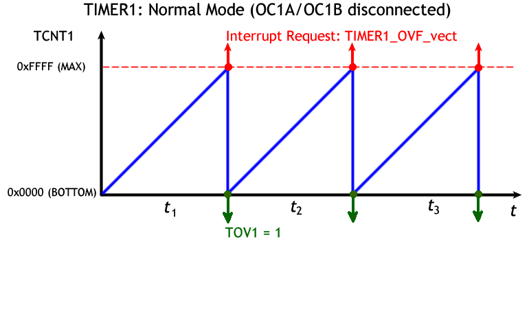 31.
31. 