
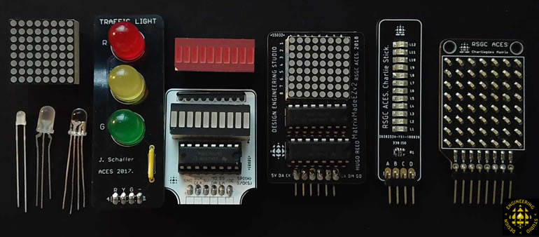
 Your comprehensive CHUMP journey has prepared you for the second half of your ICS4U experience: the deepest possible drilling into the hardware and software of modern microcontroller technology. The carefully designed sequence of register-level coding exercises below, exploiting familiar ACES' optical devices, is the final preparation for the final push in the Spring: Pure Assembly Language Programming of the AVR ATtiny84 on the Dolgin Development Platform (DDP).
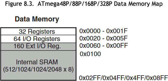
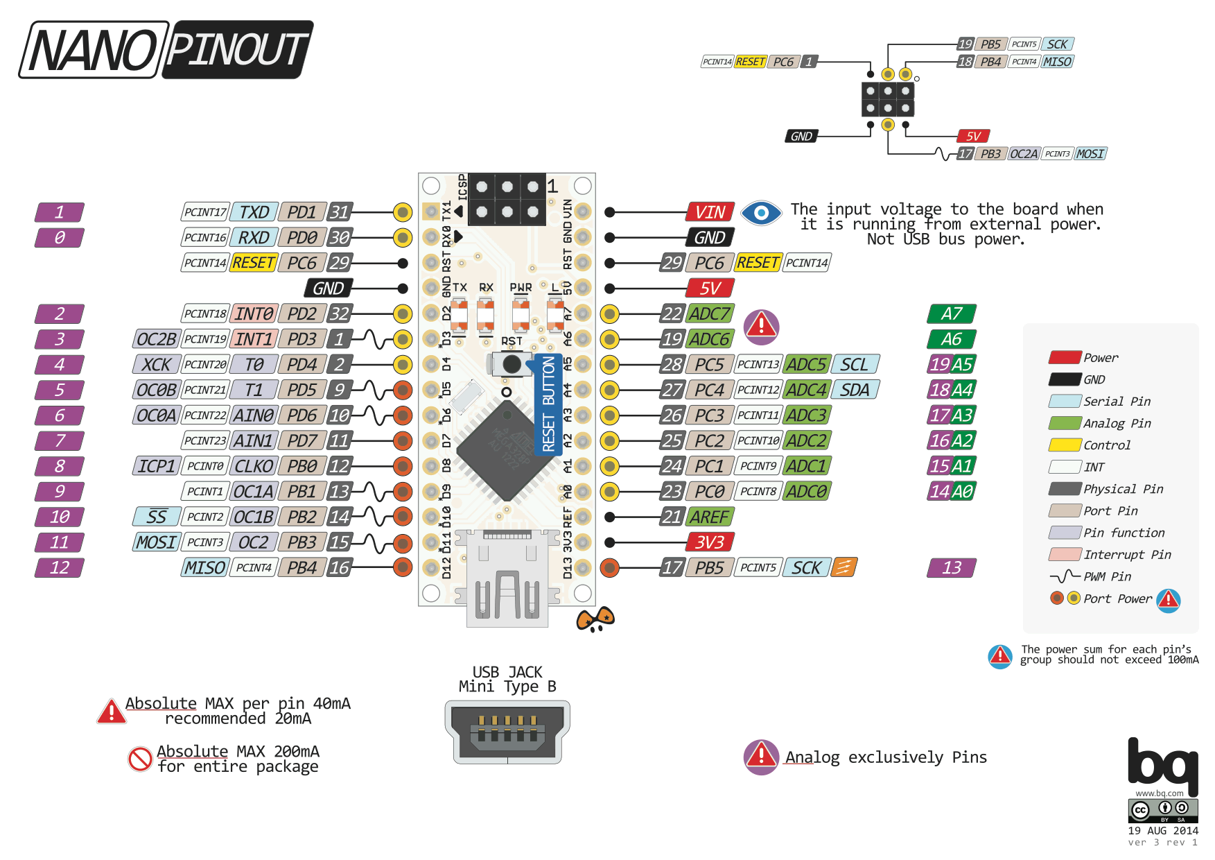
 Although these C coding exercises can be considered high-level, they call for a deeper understanding of the underlying architecture of the AVR family of MCUs. For now, this is the familiar ATmega328P, the MCU of choice for the UNO, Nano and other Arduino development boards. I often refer to this coding as mid-level, as it lies in-between high-level C (that hides much of the functionality and potential optimization) and low-level Assembly language (that you've had a brief introduction to in your 7 CHUMP instrucitons). The magic behind functions such as pinMode(), digitalWrite(), digitalRead(), and shiftOut() for example, are exposed and rewritten, in some cases, more efficiently. Direct port bit manipulation of the MCUs' General Purpose Input/Output (GPIO) Registers are called for to achieve improved performance. Conveniently, your CHUMP experience has given you the necessary insights that were lacking at the end of Grade 11 to guide these next steps.
 (Informative) Sparkfun Video Series: Level-Up Your Arduino Code: Registers
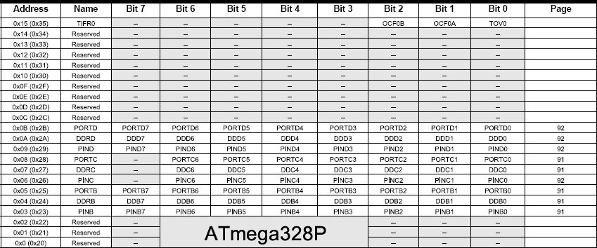
ATmega328P GPIO Register Reference
Register-Level Exercises
You may wish to create a folder entitled RegisterLevelCoding or something along those lines, to house this unique set of sketches I am asking you to develop.
 A. Bits 'n Bytes.
References
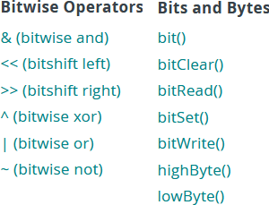
The Arduino Language Reference web page includes links to resources in support of bit manipulation.
 Two of these categories include the Bitwise Binary Operators and convenient Bitwise Functions that employ these and other operators to facilitate binary manipulation (aka bit-banging). It serves our immediate purposes with respect to knowledge and skill to code the bodies of these bitwise functions to produce the same result, ourselves.
Task.
- Create a project called BitsandBytes and drop in this shell.
- Go to our course page and insert the auto-#include header file, io328p.h that #defines the 328p's register addresses.
- Open the BitsandBytes project and review the contents of the two tabs.
- Finally, with the convenience of the Serial Monitor as confirmation (USB Cable), employ your UNO or Nano in the completion of the bodies of each of the 7 functions in the list, above right, in a local implementation rather than calling the library function.
 B. General Purpose Input/Output (GPIO) Tasks.
Note. It's not how many lines of code that matters, it's often how few.
With the awareness that the AVR's GPIO registers are accessible by name to your Arduino C sketches, develop the most efficient register-level statements you can to achieve each of the following tasks on your UNO or Nano. The employment of register-level coding strategies precludes the use of high-level statements such as pinMode(), digitalRead(), or digitalWrite(), etc.
- Note 1. The (m-n) in front of some tasks suggests the minimum number of statements required in the setup() and loop() functions, respectively, to meet their requirements.
- Note 2. Think deeply, as the task may not be as simple as the first thought you have :)
Tasks
- First off, review the Arduino's Core Library's implementation of the familiar digital pin-related functions.
- (1-2) Blink the onboard LED with a frequency of 1 Hz.
 Curious? See §13.2.2...
 (2-2) Place a bicolor LED in pins 4 and 5 and alternate flashing red and green, in a complete cycle every second.
- (1-4) Place your Schaffer Traffic Light into your UNO such that the R-Y-G pins are driven by pins 11-12-13, respectively. Develop register-level code that sequences the LEDs, continously, with a duration of 1s per LED.
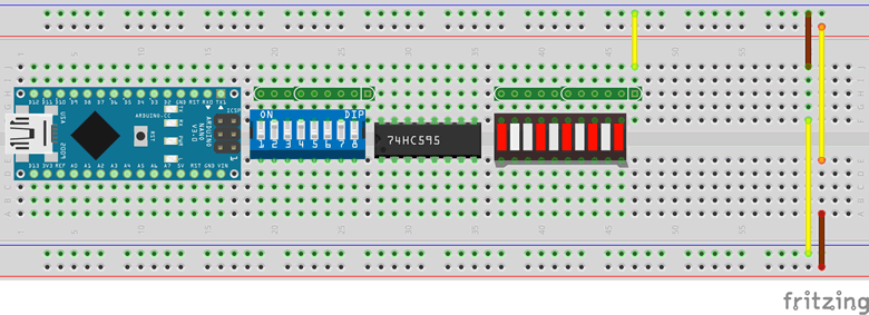
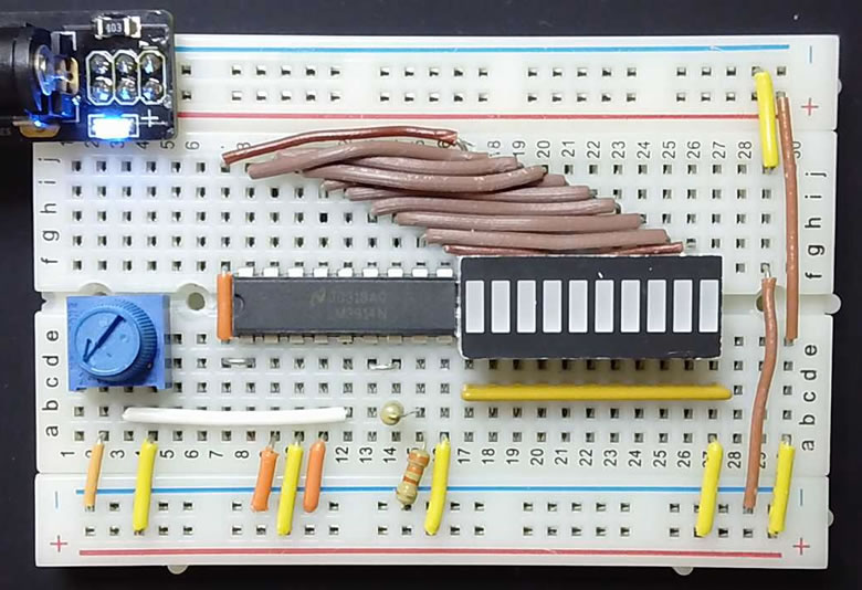
- (1-1) Add the components to a breadboard as shown below. In the first of a sequence of tasks, you are to use your Sparkfun AVR programmer, wire up all but the 595 in such a way that allows a two-statement sketch entitled, SwitchLEDEcho.ino to echo the least signficant 6 switch settings onto a bargraph.
 A Closer (Register-Level) Look at the shiftOut() Function. Click on the animated timing diagram of the shiftOut() function and study the digital signal forms, carefully. Since the orchestrated Clock, Data, and Latch forms are very similar to other protocols such as SPI and I2C, it is well worth the effort today to become familiar with their behaviour.
Task.
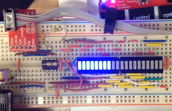
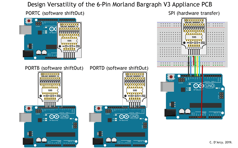
- Place your Morland Bargraph in PORTB as shown in this image.
- Develop the sketch, RLShiftOut in which you develop your own register-level shiftOut() function that uses the same four parameters as the familiar high-level shiftOut() function to echo the input from the switches onto the bargraph. For class consistency, assign the AVR pins 12, 10, and 9 as your Clock, Data, and Latch pins.
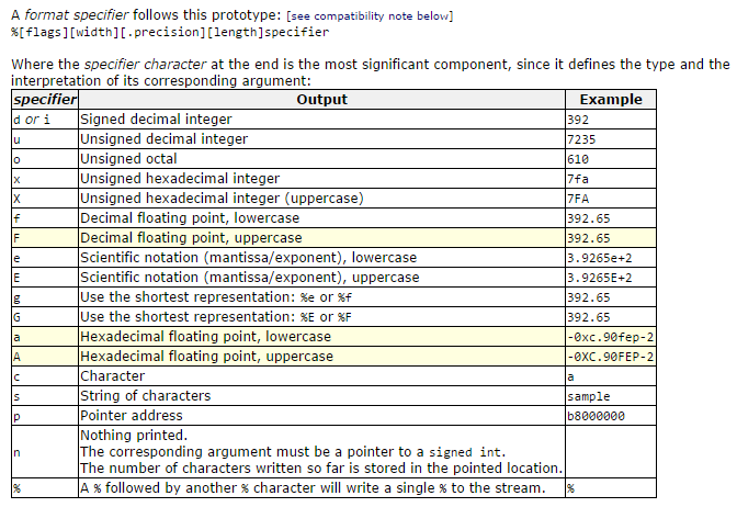
- (0-3) Binary Switches to ASCII. Make a minimum of hardware and software modifications to your breadboard prototype to permit input of the binary values of the uppercase ASCII letters [65,90] on the DIP switches and have the sketch output the equivalent characters, continuously, on your Serial Monitor.
- 12-Key Telephone Keypad. An application perfectly suited to register-level coding is the monitoring of the ubiquitous 12-key telephone keypad. So many online examples suggest an intricate scanning strategy through third-party libraries. ACES say, "Balderdash!". The 8-pin header fits ideally into PORTD of the UNO or PORTA of the ATtiny84 and can be decoded with trivial ease as the 2020/2021 ACES were required to develop in their Keypad-Matrix Echo Project. Watch this video support and give it a try yourself.
- Charlieplexed ATtiny85 20-LED VU Meter. A vivid demonstration of our AVR optimization objective can be seen in the video linked to the image, below left. For this design 5 tri-state digital pins of the ATtiny85 are used to support a 20-LED VU meter using a charlieplexing strategy.
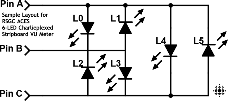
 DIY Charlieplexed 6-LED Stripboard VU Meter. The layout for a simple 6-LED stripboard VU meter that supports a charlieplex strategy appears above, right. In this exercise you are asked solder one together using the components you have been provided with in this arrangment, with L0 starting from the bottom. Three of your AVR's tri-stated I/O pins can drive this display with pins 9-11 working well if you ever intend to apply PWM the LEDs. Obtain ADC readings mapped appropriately to project onto your device.
-
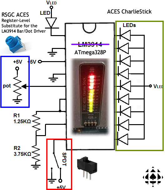 CharlieStick DOT/BAR Display. Here's an interesting challenge for your nascent register-level coding skills and to best prepare yourself for the next section devoted to a register-level manipulation of the ATmega328P's Interrupt Vector Table.
Task.
- Insert your RSGC ACES' CharlieStick (D8..D11), trimpot (A0..A2), and slide switch (D2..D4) into your UNO as shown in the photo below right.
- Save your previous StripboardVUMeter project to CharlieStick.
- With the middle pin of the slide switch sitting in D3, you can exploit the high-level attachInterrupt() function to trigger an update of your mode variable on a CHANGE signal into INT1 (Thanks Harry!) through a register-level read of the D3.
- Exploit the interrupt capabilities of the Arduino's Timer1 library to schedule an update of the analogreading of your trimpot from A1, every 100 ms. Your ISR should map the ADC reading from your trimpot to a value within the number of LEDs on your CharlieStick.
- Your loop() function simply needs to, continuously, use your mode variable to determine whether to display the level in either BAR mode (true) or DOT mode (false) in much the same manner as Pin 9 of the LM3914 Dot/Bar Display Driver.
- Charlieplex Bargraph
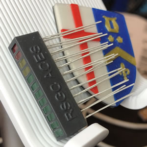
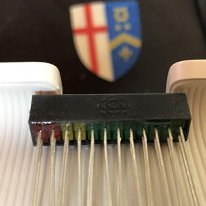
 for 2022/2023. Over the 22/23 Christmas holidays S. Appleyard and J. Rogan answered the call to design an encasement for an ACES 12-LED Charlieplexed bargragh to support an interesting Register-Level coding project we have in mind. Within two days an initial order to JLCPCB was placed for 15 units and the result was terrific. The photos below shown the first unit curing after the LEDs were epoxied in. Click to enlarge.
To be developed...
 |
 |
C. AVR Optimization: Create a Custom Library (Mega328P.h)
 You've employed a number of libraries over the past year or so, from the Arduino Core libraries (transparently included in every project) to third party libraries (through the explicit use of the #include directive) that hide the functionality of complex devices and tasks through convenient object instantiation and subsequent member function calls. Well, it's time to establish and exploit your own custom library. For the first attempt, you'll pack useful ATmega328P resources (constants, data structures, functions, etc.) of your own design and selection. You'll gain some familiarity with the process from completing the directed exercises below. In doing so, future projects can reuse and enhance this code to yield the desired outcomes in less time, and with improved confidence.
 Task 1. Separation of Code. First, let's consider some code that is generic enough to be reusable in future projects and confirm that it can exist in a separate file.
- Open the previous project, CharlieStick, and save it as CustomLibrary.
- Click on the Down Arrow icon in the top right corner under the Serial Monitor icon, and select New Tab.
- Enter Mega328P.h in the text box and press OK.
- Cut the identified resuable resources out of CustomLibrary, click on the new tab, and paste them into your Mega328P.h file.
- Return to the CustomLibrary tab and, just under the opening comments, add the directive, #include "Mega328P.h". Be sure to use the double quotes which reference a header file within the same project.
- Compile (Verify) to confirm all your code remains reachable, despite being split into separate files.
- Upload and confirm everything is functioning as before.

 Task 2. Centralized Access to Common Code. Now, we should place your library (the Mega328P.h file) in a folder that is accessible to all future projects.
- Close the Arduino IDE.
- Use the Finder to locate your personal Arduino sketch folder. Within this folder you have a libraries folder. This is where the Arduino IDE's Library Manager expects to find third-party libraries you have previously downloaded and installed.
- Within this libraries folder, create a new folder called, Mega328P.
- Find your CustomLibrary project folder, remove the Mega328P.h file and paste it in the newly created libraries\Mega328P project folder.
- Now, reopen the Arduino IDE, and the CustomLibrary project. Notice the tab with the Mega328P.h file is no longer there.
- Place your cursor on a new line, just after your opening comments.
- Open the Include Library feature within the Sketch menu, find the Mega328P library, and select OK. You'll notice the directive, #include <Mega328P> has been inserted into your sketch. Notice the angle brackets (instead of the double quotes as before) to indicate the library is NOT within the same project.
- Upload the code. It should be good and you can now do the same for future projects.
- As you develop new features and functions you may wish to add these resources to your Mega328P.h library file.
- ACES are committed to efficiency, accuracy, and high productivity. This world needs engineers that bring all three and custom libraries promote this goal.
Task 3. Syntax Highlighting: keywords.txt. Syntax highlightig is a useful feature that enhances code development. The key to ensuring the personal assets of our custom libraries are supported by the Arduino IDE's conventional syntax highligting scheme is a separate text file called keywords.txt.
- The official Ardiono documentation for the formatting of library keywords can be found here.
- Close the Arduino IDE.
- Download and save this keywords.txt file to your libraries\Mega328P folder.
- Open the keywords.txt file and edit it to reflect the syntax highligting appropriate for the use of your assets.
- Save the file.
- Open your CustomLibrary project and confirm the syntax highlighting is functioning as designed.
Congratulations! You can now proceed to Interrupts Using Register-Level Coding on the ATmega328P.
