This page should be undertaken only after completing,
AVR Optimization #1: Introduction to Register-Level (Mid-Level) Coding of the ATmega328P
With bit-level coding of the ATmega328P's Digital IO registers (0x0020-0x005F) under your belt, it's time to excavate the next level of SRAM Addresses.
 Libraries (Arduino and Third-Party). Libraries offer the novice coder the classic tradeoff between deep understanding and speed of project development. As your embedded skill set matures, greater understanding, clarity, confidence, and efficiency are typically found in the direct manipulation of the MCU's hardware using as close to its native instruction set as possible. To this end, in the exercises below we will do our best to avoid using many of the arduino and third-party libraries suggested by web tutorials in favour of direct register manipulation. On the other hand, establishing and maintaining your own personal library of tested resources is to your significant advantage as we will also introduce in the tasks below.
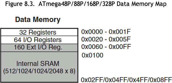 Review the ATmega328P's SRAM Register File one more time.
Here's a question for you. Based solely on the undefined (grayed out) addresses of the 328P's digital IO ports, what ports might you expect to find if you examined the ATmega2560's Register File?
Interrupts: The  to Software Optimization
 Our ACES program places a high premium on productivity. Since organization and efficiency drive productivity, it is necessary to dig deeper into the architecture of the AVR microcontroller to familiarize ourselves with its capabilities in support of our code strategies and structures.
It's pretty obvious that watching your phone constantly for incoming text messages is not a productive use of your time. Likewise, standing at your front door waiting for that Amazon delivery is also a colossal waste of time. Finally, you could probably bring in the green bins from the curb rather than watching and waiting for the kettle to boil up your next cup of tea. The good news is that most of these 'Events' come with associated 'Alerts'. Today's microntrollers are no different and the AVR family is no exception. For example, the analogRead() function initiates an analog-to-digital conversion process that takes time. To the human this takes virtually no time at all but, to the MCU, these are precious clock cycles that could be used to perform a parallel task while the conversion is waiting to complete. So, wouldn't it be terrific to simply launch an analog-to-digital conversion, then do something else and wait to be alerted (ie. interrupted) that the conversion is complete and ready for reading? This sounds highly productive. The AVR line of MCUs has a builtin architecture for alerting or interrupting your code when it finishes certain tasks. We need to exploit this.
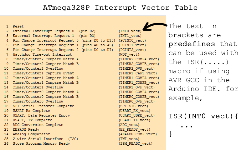 The most efficient software for the embedded developer is typically none at all. This may sound flippant but if the hardware platform your developing on has native circuitry for a given task, there is (likely) no software routine that will perform more efficiently. Review the ATmega328P's Interrupt Vector Table (IVT) to the right.
This table suggests there are as many as 26 different sources of events on the ATmega328P that have the ability to complete the following sequence,
- Automatically interrupt whatever your code is doing at that instant
- Preserve the current 'state' of your program in its entirety
- Transfer control to another section of your code ( remember CHUMP's Program Counter? )
- Execute whatever instructions you have coded as a 'response'
- When the response code is finished, automatically return you to the instruction you were executing the moment the interrupt occurred
- Restore the saved state of your code
- Allow you to continue on as before
The order in which these Interrupts are listed carries with it additional meaning. Implied in this order is a sense of priority. By being #1, a hard (or soft) Reset has the highest prioritiy and takes precedence over any other task your MCU is performing, resets the Program Counter to 0, and code starts from the beginning again. We'll start our formal implementation of Interrupt coding with the Reset Interrupt.
Interrupt #1. Reset
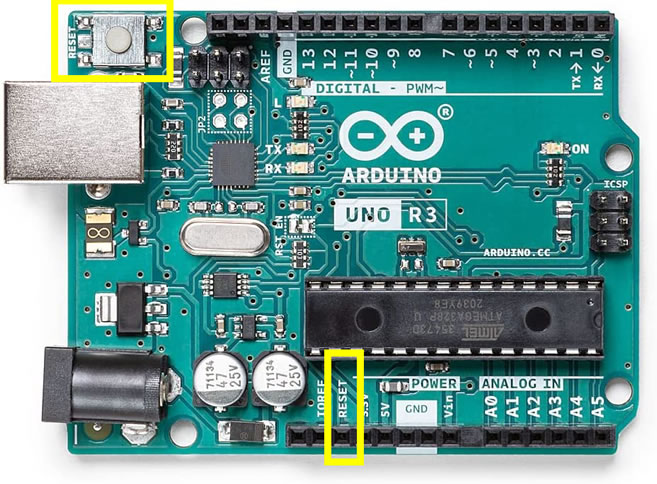 You are familiar with the effect of pressing the Reset button on the UNO or Nano, however further optimization is accessible through a deeper understanding of the subtleties the various Reset sources of AVR MCUs. These sources can be detected and subsequently impact how your code chooses to restart.
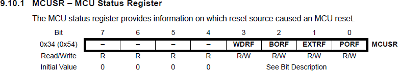
Chapter 11 of the ATmega328P datasheet introduces the concept of System Control and, in particular, the Reset Function. The MCU offers four hardware Reset triggers that include: Power On, External, BrownOut, and Watchdog. At the end of this chapter, there is a description of the Registers that can be inspected and manipulated. For our purposes, we'll limit ourselves to a simple distinction between the Power On and External Reset triggers. Page 54 of the ATmega328P datasheet presents a detailed discussion of the MCUSR Register, (see: ATmega328P Register Summary) in which the source of a Reset can be identified through the use of flags (bits).
Task.
 Span a bicolor LED across digital pins 8 and 9 of your UNO such that the green anode is in pin 8.
- Create the project ResetInterrupt328P and replace the default sketch with this one: ResetInterrupt328P.ino
- Review the fully functional code and note the (unsuccessful) attempt to identify the source of the System Reset: MCUSR's WDRF, BORF, PORF and EXTRF flags
- Upload the code and confirm the UNO lights the green LED. Which of the four Reset sources do you think this is an example of ?
- Launch the Serial Monitor and note that the green LED Lights. Which of the four Reset sources do you think this is an example of ?
- Temporarily disconnect the UNO from your laptop and then plug it back in. The green LED lights. Which of the four Reset sources do you think this is an example of ?
 Press the UNO's onboard Reset button and confirm the green LED lights. Which of the four Reset sources do you think this is an example of ?
- Grab a breadboard and wire a momentary button to the UNO's female Reset header with a 10 kΩ pullup resistor as the default state. Pressing the button should place a ground into the Reset pin.
- Press your button to confirm a System Reset. Which of the four Reset sources do you think this is an example of ?
Interrupt #2 and #3. External Interrupt Requests 0 and 1 (INT0 and INT1)
 From your previous year's experience you are aware that MCUs have digital pins that can be configured to respond to changing voltage levels presented by external behaviour. By way of example, the ATtiny84 has ONE such pin, the ATmega328P has TWO, and the ATmega2560 has SIX!
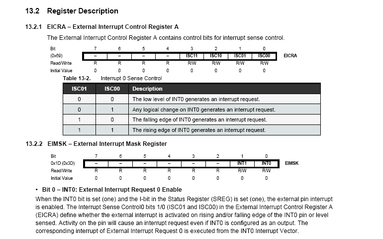
The two on the ATmega328P are referred to as INT0 and INT1 (digital pins 2 and 3 respectively). As can be seen from the IVT (below, left), each has a separate vector address and immediately follow the System Reset Interrupt in order of priority. An excerpt from Chapter 13 of the ATmega328P datasheet appears below right. Configured correctly, the ATmega328P can sense and respond to four voltage level behaviours presented on the INT0 and INT1 pins.
 (Informative) Sparkfun Video Series: Level-Up Your Arduino Code: External Interrupts
Task.
- For this exercise you are asked to assemble a prototype similar to the one shown below. The goal is to enable the user to increase or decrease the digit displayed on the 7-Segment device through the use of FALLING edges triggered by button presses and presented on INT0 and INT1.
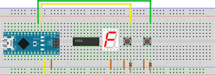
 Feel free to incorporate your 4511 BCD decoder for a presentation of decimal digits (0-9), or wire the segments independently and present hexadecimal digits (0-F) through a segment LUT.
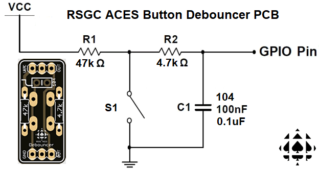
- You may wish to debounce your button inputs for a better user experience.
- Create the project ExternalInterrupt7Segment and drop in this shell: ExternalInterrupt7Segment.ino
- On a System Reset the display should show 5 initially.
- Configure the INT0 and INT1 Interrupts to have the display increase and decrease the digits displayed respectively. TIP. Since External Interrupts are commonly implemented, you may wish to add meaningul #defines in your Mega328P.h library, designed as ORed flags for LOW, LOGICAL, FALLING and RISING.
Interrupt #4, #5, and #6. Pin Change Interrupt Requests 0, 1, and 2

 for 2022. 20/21 ICS4U ACES were the first class to be introduced to the ACES Rotary Encoder. A few short months later A. Goldman and S. Atkinson used their familiarity with the device to support their
  Clue Capturer prototype for their ECE190 course at Waterloo. Their achievement is the inspiration behind this project segment of your journey.
(Informative) Sparkfun Video Series: Level-Up Your Arduino Code: Rotary Encoders
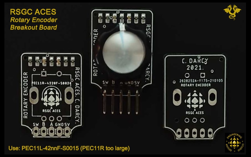 Your Bourns PEC11L-4215F-S0015 Rotary Encoder offers three sources for useful interrupts. These are A, B, and SW. Given that the ATmega328P only provides two external interrupts, we look beyond INT0 and INT1.
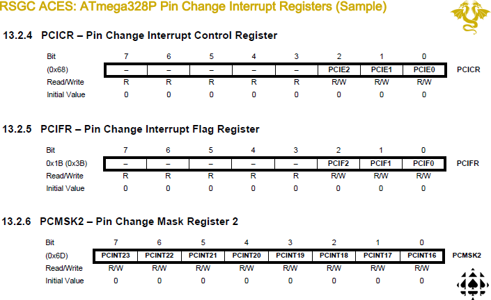
In reading Chapter 13 of the ATmega328P datasheet you discover that interrupts can be triggered on ANY digital IO pin in the event that a logical level change has been detected in hardware. A little bit of software detective work is required to determine which pin was triggered as the 24 pins (PCINT0..PCTIN23) are organized into three separate banks defined by the respective Ports. Pins on PortB are mapped to PCINT0..7, pins on PortC are mapped to PCINT8..15, and pins on PortD are mapped to PCINT16..23.
A sample of the applicable Pin Change Interrupt registers of the ATmega328P appears below.
'Get Acquainted' Tasks: Rotary Encode Pin Change Interrupts
- Wire your RSGC ACES Rotary Encoder to your Nano such that the supply pins are connected and A and B place their signal into INT0 and INT1, respectively.
- Create the project RotaryEncoderNanoPlotter and drop in this sketch. Upload and confirm with the Serial Plotter.
- Adjust the wiring to deliver the A and B output of the Encoder to digital pins 4 (PCINT20) and 5 (PCINT21) (PCMSK2)
- Create the project RotaryEncoderNanoPCInts, and drop in this sketch. Upload, examine, and confirm with the Serial Monitor.
Interrupt #7. Watchdog Time-Out Interrupt (with and without a System Reset, as well as Power-down sleep mode)
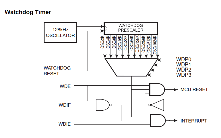
 The Watchdog Timer (WDT) is an MCU subsystem that can be configured to perform scheduled functionality. From the ATmega328P datasheet, 'The watchdog timer is clocked from an on-chip oscillator which runs at 128kHz. By controlling the watchdog timer prescaler, the watchdog reset interval can be adjusted as shown in Table 11-2 on page 55.". Review this Excel workbook to lock in the connection between crystal oscillation binary counting and frequency division:
 BinaryCountingFrequencyDivision.xlsx
Note. Your MCU's onboard Timer/Counters (discussed in future lessons) can be used for the general task of periodic scheduling but are best reserved for their signal modulation and demodulation capabilities if possible rather than mere overflow interrupts.
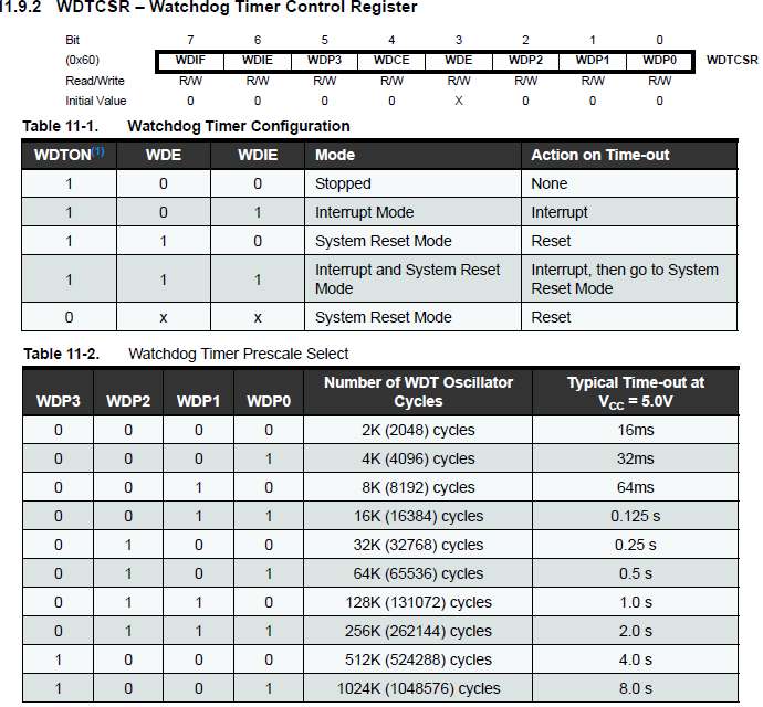 From Table 11-1 to the right it can be seen that there are FIVE courses of action that that can be taken following the end of an elapsed WatchDog Timer interval. We'll start with a simple Interrupt.
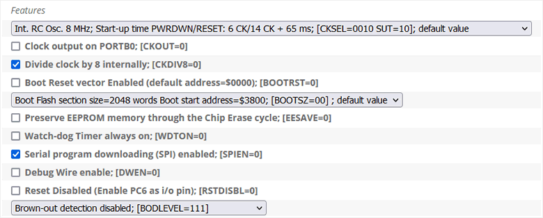
The WDTON fuse determines whether the WDT subsystem is required as a fail-safe function (see AVR FUSE Calculator). The default setting has it off (WDTON=1). Should regularly-scheduled, unconditional System Resets be required, advanced applications may wish to set this fuse (WDTON=0) to enable this protection feature.
WDT Tasks.
In the exercises that follow we'll explore the three WDT Modes of operation,
- Interrupt Only (No System Reset)
- System Reset
- Interrupt followed by a System Reset
 Watchdog Time-out Interrupt Only (no System Reset). For starters, you'll configure the WDT to generate an interrupt at specific intervals of time based on an internal counter clocked to the WDT's internal 128 kHz oscillator.
- Create a new project entitled WDT328PInterrupt and drop in these two files: WDT328PInterrupt.ino and prescalers328WDT.h.
- Open the WDT328PInterrupt project.
 Click on the prescalers328WDT.h tab and review the contents. Consider copying these constants to your personal Mega328P.h library now or simply add an #include directive to prescalers328WDT.h in your WDT328PInterrupt driver to access these ORed flag constants.
- Using the embedded comments as a guide, complete the configuration of the WDT in your WDT328PInterrupt driver.
- Launch and confirm.
- How could a 5-minute interval between LED state transitions be configured with the WDT?
 (preparation for a future exercise) Save your working WDT328PInterrupt project to a new one entitled, WDT328PInterruptforADC. Insert a trim pot (as UNO appliance) into A0-A2 and configure it to deliver a varying voltage into A1. Configure a WDT Interrupt to schedule, obtain, and display an analog reading from A1 every 0.5s to the Serial Monitor.
 Watchdog Time-out Interrupt Followed by a System Reset. You may recall from the earlier Interrupt #1. Reset that there are FOUR triggers for an ATmega328P System Reset as reflected through flags in the MCUSR register, one of which is a WatchDog Timeout Reset Flag (WDRF). Note: Despite my best attempts to have the Arduino sketch identify and display the source of the Reset, it appears that too much code is executed in the avr-gcc toolchain before our code gets to read the MCUSR. If you find a way to do so, let me know!
 A second WDT mode allows the programmer to generate a System Reset only AFTER a WDT Interrupt has occurred. In this way, the program can preserve the state of the system (in EEPROM, for example) prior to restarting. Reading EEPROM on startup is one way continuity can be preserved between sessions.
- Open your WDT328PInterrupt project and save it, as is, to a new project entitled, WDT328PInterruptANDReset
- Consult the WDT's Block Logic diagram to the right to identify the simplest modification required to have a System Reset follow a Watchdog Interrupt.
- Make the single edit and upload to confirm that the extended LED session occurs after the single brief LED on is observed.
Imagine a remotely-situated solar-powered, MCU-based sensor device (ie a roof, mountain top, at-sea, space, etc.) that collects (and possibly transmits) data to a central location. The third WDT mode that deserves to be mentioned is a System Reset only, without the benefit of a prior interrupt. Regularly-scheduled reboots could make the difference in avoiding costly repairs and more space junk. A simple modification to the previous code would result in a System Reset ONLY mode. So, for a final look at the WDT we turn our attention to the System Reset ONLY and an interesting context: overall MCU power consumption.
Imagine, again, a solar-powered MCU-based system. Understandably, optimum use of power would contribute to its viability and sustainability. This final segment provides some insights into how some aspects of such a prototype could be implemented to conserve power between readings. One 24-minute video I encourage you to watch is Kevin Darrah's Low Power Arduino! Deep Sleep Tutorial. This video presentation contains applicable and inspiring material for our final WDT investigation.
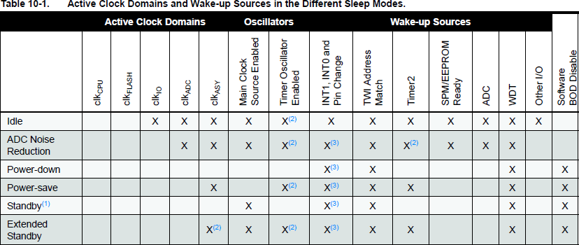
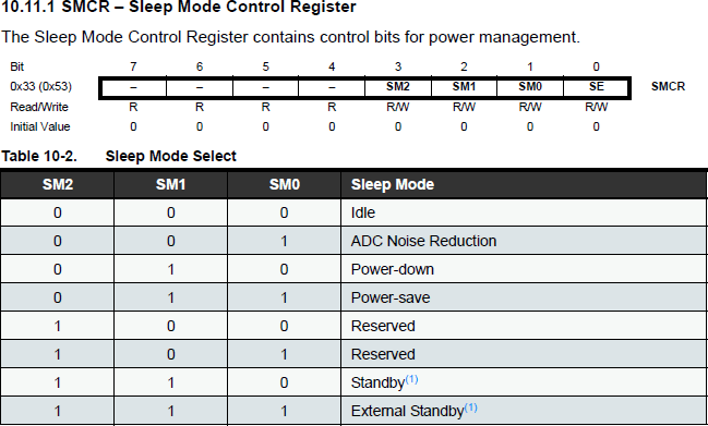
 Power-Down (Sleep) Mode. With the WDT tool confirmed as a scheduler, if there's nothing to be done between interrupts the MCU's power demands should be reduced to a minimal level after configuring the WDT interrupt to wake up the MCU from a lower-power sleep mode. One such mode is the Power-down sleep mode. Pages 40-41 of the ATmega328P datasheet says, "When the SM2...0 bits are written to 010, the SLEEP instruction makes the MCU enter Power-down mode. In
this mode, the external (16 MHz) oscillator is stopped, while the external interrupts, the 2-wire Serial Interface address
match, and the Watchdog continue operating (if enabled). Only an External Reset, a Watchdog System Reset, a
Power-Down (Sleep) Mode. With the WDT tool confirmed as a scheduler, if there's nothing to be done between interrupts the MCU's power demands should be reduced to a minimal level after configuring the WDT interrupt to wake up the MCU from a lower-power sleep mode. One such mode is the Power-down sleep mode. Pages 40-41 of the ATmega328P datasheet says, "When the SM2...0 bits are written to 010, the SLEEP instruction makes the MCU enter Power-down mode. In
this mode, the external (16 MHz) oscillator is stopped, while the external interrupts, the 2-wire Serial Interface address
match, and the Watchdog continue operating (if enabled). Only an External Reset, a Watchdog System Reset, a
Watchdog Interrupt, a Brown-out Reset, a 2-wire Serial Interface address match, an external level interrupt on INT0 or INT1, or a pin change interrupt can wake up the MCU. This sleep mode basically halts all generated
clocks, allowing operation of asynchronous modules only."
- Although they are not incorporated into this task (in favour of direct register-level manipulation) the Arduino Power Management libraries (sleep.h and power.h) are worth reviewing for their insights and assets.
- If necessary, review the applicable Register Descriptions for the Watchdog System Reset starting on page 54 of the ATmega328P dataheet.
- Create a new project entitled WDTInterruptfromSleep and drop in this completely functional sketch: WDTInterruptfromSleep.ino.
- Attach your UNO/Nano and upload the code.
- Launch the Serial Monitor and observe the output.
- Participate fully in the class review and discussion.