 I've found over the years that a good way to gain new insights and acquire new knowledge is to immerse yourself in a compelling project and take stock of where it leads you. Lowering or stepping down voltage in a circuit is a common requirement of many systems. Resistors in series, forming a voltage divider, is one such approach. Voltage regulators such as the LM78XX series is another option. The issue with both of these are the tradeoffs. The former comes at the expense of current loss and the second the poor efficiency due to the conversion of voltage to heat loss. The better solution is a step down or buck converter. We'll explore this strategy in this exercise.

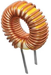
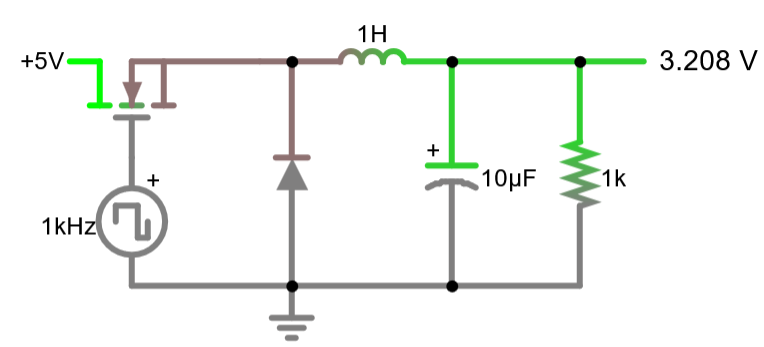
A simple model for a DC DC Buck Converter appears above (Reference: Falstad: Power Conversion: Buck Converter). This particular example shows how a 5V input is stepped down to a 3V output by employing some familiar components (P-Channel MOSFET, Inductor, Capacitor, Diode and load Resistor), athough 1 H inductor is quite large. A switching (PWM) frequency is applied to the Gate pin of the MOSFET to turn the transistor on and off, rapidly. This circuit is the basis for Switched Mode Power Supplies (SMPS) like many of your AC/DC Adaptors. Here's a fairly accessible video explaining how this circuit works:  Buck Converter.
References:
- Creating a Switching Frequency
- The Transfer Function of the Buck Converter
1. Creating a Switching Frequency (PWM)
References
- AVR Optimization #1: Introduction to Register-Level (Mid-Level) Coding of the ATmega328P
- AVR Optimization #2: ATmega328P Interrupts Using Register-Level Coding
- AVR Optimization #3: ATmega328P Timer/Counter Interrupts Using Register-Level Coding
1.1 Review the source code for analogWrite(pin, value);
1.2 Review the source code for RegisterLevelTimer1Mode15BuckConverter
2 The Transfer Function of the Buck Converter
References
 I've found over the years that a good way to gain new insights and acquire new knowledge is to immerse yourself in a compelling project and take stock of where it leads you. Lowering or stepping down voltage in a circuit is a common requirement of many systems. Resistors in series, forming a voltage divider, is one such approach. Voltage regulators such as the LM78XX series is another option. The issue with both of these are the tradeoffs. The former comes at the expense of current loss and the second the poor efficiency due to the conversion of voltage to heat loss. The better solution is a step down or buck converter. We'll explore this strategy in this exercise.