2023-2024 ICS4U Independent Study Projects (ISPs) |
![]() Independent Study Projects. Please read our overview on why ACES pursue Independent Study Projects so vigorously.
Independent Study Projects. Please read our overview on why ACES pursue Independent Study Projects so vigorously.

 To my mind, the characteristics of a great project include such aspects as imagination, creativity, a degree of risk and, sometimes, even simplicity, to name a few. Check out the flashlight circuit 'board' this guy made out of little more that a piece of paper and a pencil? Simple, but inspiring.
Consider a problem that needs a solution. Boyan Slat did at age 17 when he was in high school; four years later he is
To my mind, the characteristics of a great project include such aspects as imagination, creativity, a degree of risk and, sometimes, even simplicity, to name a few. Check out the flashlight circuit 'board' this guy made out of little more that a piece of paper and a pencil? Simple, but inspiring.
Consider a problem that needs a solution. Boyan Slat did at age 17 when he was in high school; four years later he is Also, don't underestimate the value of an enterprise/entrepreneurial aspect to your project that could see a number of units of your project in the hands of future ACES, for sale in the Dragon's Lair or beyond, reaching an even a broader audience.
| ACE | Short ISP (20%) Saturday September 17 |
Medium ISP (20%) Saturday January 13 |
Long ISP (20%) Saturday April 20 |
|---|---|---|---|
| Proposals >>> | Short ISP Proposal | Medium ISP Proposal | Long ISP Proposal |
Jacob C. . |
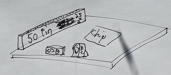
32 Pin SIMM Old RAM Module
The plan is to create a module that will work with micro-controllers and micro-processors. Idea: Hook up an EEPROM’s data pins to the refresh pins and use a counter IC to go through each address from 0-9. A read pin and write pin will then be used to change the address and therefore change the way the EEPROM interacts with the CAS and RAS pins on the ram. The EEPROM will also control which set of 10 bits are displayed on the rams address. Note: I understand that EEPROM is a bit excessive, but I like EEPROM and it will be an interesting method. Maybe I can let the rest of the EEPROM be accessed separately. I want to try and do this without a microcontroller b/c it feels cheating, other than for testing.HARDWARE 328P SOFTWARE Arduino C DESIGN I would like to create a PCB in EAGLE and get it made with JLCPCB. Maybe even try to make my own RAM socket using 3d printing and adding metal bits, b/c its hard to get 30 pin SIMM RAM sockets. COMMUNICATION Serial communication for debugging and for confirming that ram values, but not a core part. MECHANICAL N/A |
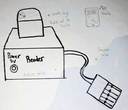
Nintendo Card Reader and Emulator
DESCRIPTION This project will focus on dumping the contents of game cartridges and hopefully emulating one. The reading is straightforward. The community has discovered that the pins use a Nintendo proprietary SPI-like 8-bit bus. After taking apart a Nintendo switch and looking at the insides, I will 3D model a similar device and print and make it. The emulating won’t be as straightforward because of tiny encasing and high-density data. Most likely a cable-like device will be made instead of a cartridge.The microcontroller that will be doing all of the work will be an Arduino Uno R4 WIFI. It has a fast 32-Bit ARM chip and its WIFI module allows for creating an access point and making a TCP/IP server to interact with it remotely, removing the need for a tedious display or cable for serial to communicate to a person or computer. The cartridge has 17 total pins .I will use resistors on the pins just in case. The documentation isn’t that detailed. |
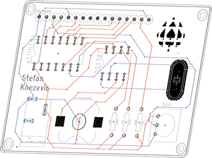
STM32F100R4T6B Microcontroller
HARDWARE STM32F100R4T6B SOFTWARE C DESIGNPurely on a PCB, I plan to make the PCB the art. I plan it to look kind of like an UNO where it has female header pins. COMMUNICATION It will use UART connected to a FT232RL chip to allow USB communication MECHANICAL N/A |
Graham D. . |
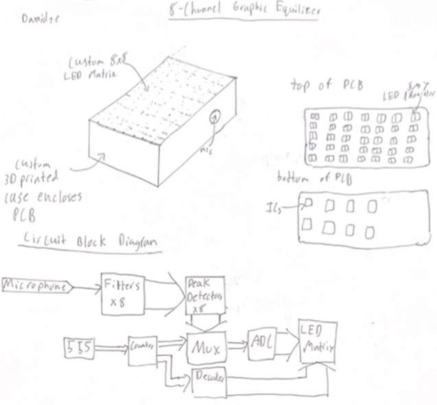
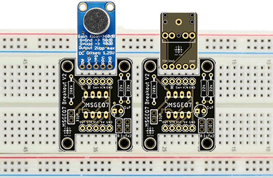
8 Channel Graphic Equalizer
HARDWARE LM324N opamps will be used for all of the filters and the ADC. A standard electret microphone will be used for the audio input. This signal will then be amplified hopefully with an AGC circuit, so that it is of a suitable amplitude for the filters and display. The matrix driver circuitry will be driven by a 555 timer and features a 74HC193 counter, a 74HC42 decoder, and a 74HC4051 multiplexor. SOFTWARE N/A DESIGN A custom PCB or PCBs featuring a combination of THT and SMT components will be designed to house all of the circuitry, and feature a custom 8x8 led matrix. A custom matrix will be designed so that the size of the matrix can be determined to create the best appearance. A 3D printed case and diffuser for the matrix will be designed to fully enclose the PCB COMMUNICATION N/A MECHANICAL A custom PCB or PCBs featuring a combination of THT and SMT components will be designed to house all of the circuitry, and feature a custom 8x8 led matrix. A custom matrix will be designed so that the size of the matrix can be determined to create the best appearance. A 3D printed case and diffuser for the matrix will be designed to fully enclose the PCB. |
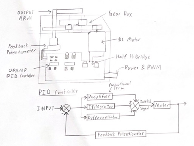
PID Servo Motor
DESCRIPTION I plan to create a Servo motor using a DC motor, a PID controller, and a custom gearbox. I will use basic opamp circuits to create the PID controller, which will drive the DC motor. The PID control system will be created from differential, inverting, differentiating, integrating and summing amplifier circuits. The motor will connect to a gearbox which will increase the torque while decreasing the rate of rotation. Additionally, the gearbox will connect the feedback potentiometer to the output. Due to the potentiometer, the servos range of rotation will be limited to 270º. |
ATtiny214/414/814 Development Platform
HARDWARE ATtinyx14 SOFTWARE C & Registers DESIGN Fixed PCB COMMUNICATION UPDI and Serial MECHANICAL N/A |
Vithusan J.
|
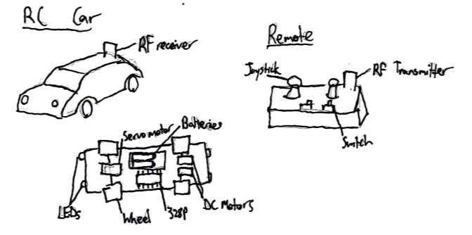
Remote Control Car
HARDWARE 328P. It will include LEDs for head and tail lights with a switch on the remote to control them. SOFTWARE Arduino C DESIGN Fusion360 will be used to design the body of the car and the case for the remote. Eagle will be used to design custom PCBs for both the car and the remote. COMMUNICATION RF MECHANICAL DC Motors will be used to control the rear tires (forward and backward motions). A Servo motor will be used to control the front tires (steering). |
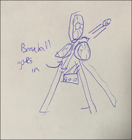
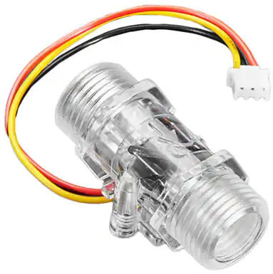
Pitching Machine
DESCRIPTION For this project, I plan to create a pitching machine. It will be able to launch baseballs to simulate pitches, which would be used to practice batting. To do this, there will be three spinning wheels, positioned equally spaced apart in a circular shape where it will accelerate the ball. By changing the speeds of the wheels, different pitches can be imitated (like a curveball). To control the pitch-type and the speed of the pitch, there will be a control panel with buttons. |
DIY Gearbox
HARDWARE SOFTWARE C, 328P DESIGN Almost all components (including gears and shafts) of this project will be designed on Fusion360 and then 3D-printed. There will also be an acrylic face of the box to see the inner workings in action. COMMUNICATION MECHANICAL A DC motor will be used to power the 3D Printed Gearbox |
Liam M. |
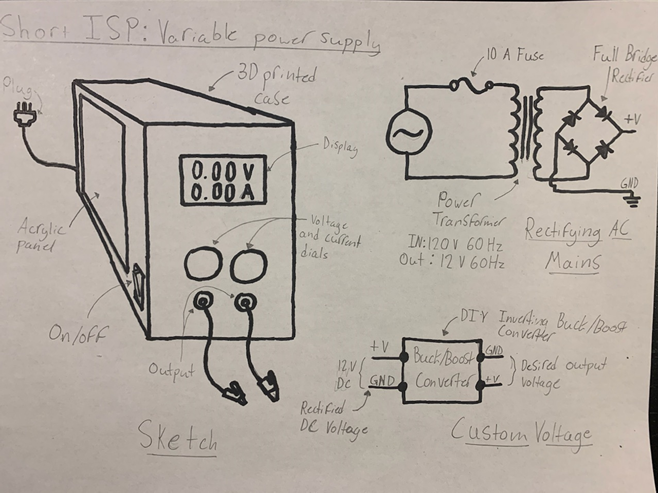
DIY Variable Power Supply
HARDWARE 328P. The device will work by first stepping down the mains AC voltage with a transformer before putting the secondary winding’s output through a full bridge rectifier, turning it into a low-voltage DC output. This will then be smoothed out before going into a buck/boost converter (inverting) before finally leading to the output of the device. SOFTWARE Arduino C. Software will be implemented to create a feedback cycle to limit the current draw and output voltage, and also drive the display. The feedback cycle is required to keep voltage steady with different loads. DESIGN Buck/Boost converter PCB designed in EAGLE, made by JLCPCB. The case will be primarily 3D printed with an acrylic panel to showcase the internals of the device. A PCB will be designed and implemented for the buck/boost converted to go inside the case. COMMUNICATION N/A MECHANICAL N/A |
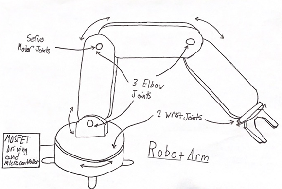
5 DoF Robotic Arm
DESCRIPTION This ISP will be to build a robotic arm with 5 degrees of freedom (DoF). This arm will have a simple pincer jaw on the end effector and other than that will have three “elbow” joints and two “wrist” joints, meaning three joints used for normal positioning and two for rotation. The arm will have a diverse range of motion and be able to move to defined coordinates in 3D space as well as move along lines within 3D space. This is not a trivial task as to accomplish this every joint must work together. |
Rocket Telemetry
HARDWARE MCU: ATtiny414 SOFTWARE C/Processing DESIGN This device will be built on a PCB and mounted onto a model rocket, so it will have to be small in order to facilitate that. COMMUNICATION I will use RF modules to communicate between the rocket and my computer. These will have to be long range modules, likely a 2 km model I found. MECHANICAL N/A |
Alex S. |
Reach For The Top Main Console
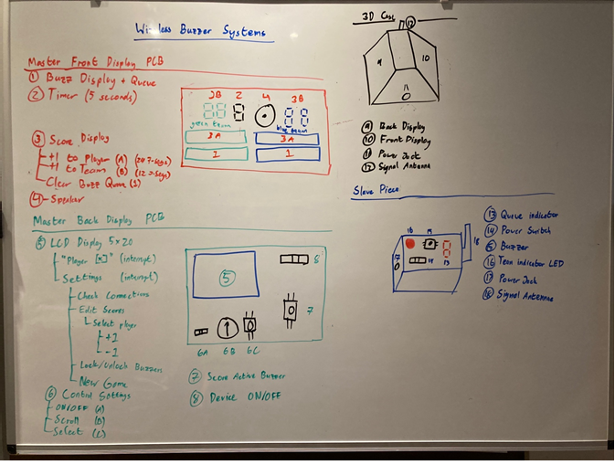
The first part of this project is the main console. The main console will have the scoreboard for individual players and teams on one side using seven segment displays and their accompanying ICs. The second side will have a control panel to alter scores and game settings using a button (PBNO) to select, a potentiometer to scroll through options, and an LCD panel to display the options. This device will be used by the game master. The main console will also be built with the timer, buzzer, and RF modules which will be employed with the second part of this project. The second part, which will be the next ISP, will introduce 12 peripheral devices which wirelessly communicate with the main console. These devices will be used by the players, and there will be six for each team. Interacting with these peripheral devices (which just have a button for HID) will activate the buzzer and countdown timer on the controlling device.HARDWARE 2560 SOFTWARE Arduino C and Libraries DESIGN EAGLE and Fusion COMMUNICATION RF MECHANICAL None |
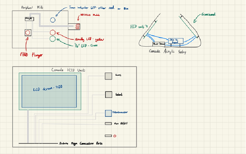
RFTT – Console Completion and Peripherals
DESCRIPTION As a continuation of the previous project, this ISP aims to improve the scoreboard console for HID interaction, and sets it up for RF communication with six or twelve peripherals, which will be used by the players. The console expansions will take place on the same development board and Arduino, with added connections to a second PCB, as well as two RF modules (the nRF24L01 can only communicate with six other peripherals as a controller). The second PCB on the console will be a corrected version of a PCB design made in the first phase. The peripherals only require enough pins to acquire button signals, light three displays, and control the nRF24L01 RF module which they communicate with (which should be just nine pins). The LEDs will display the team the device is set to, and indicate if the peripheral has been activated fast enough for the player to answer a question (by an RF signal from the console). Each peripheral will be encased, and each case will have a number (1 to 6) to indicate the player number of the team in connection with the individual players’ scores shown on the console.HARDWARE (84 and 2560) The development board on the console is controlled by the same ATmega2560 Arduino Mega as the previous project. The peripherals will be using ATtiny84 µCs, as their functionality requires fewer pins SOFTWARE High and Register level C. RF24 Library and, possibly, SPI. DESIGN Acrylic casing for the console will be designed in Adobe Illustrator. This case will mount the console PCBs and development board as a frame. The peripherals will have 3D printed cases and PCBs designed in Fusion and Eagle respectively, and may have acrylic covers. COMMUNICATION RF MECHANICAL N/A |
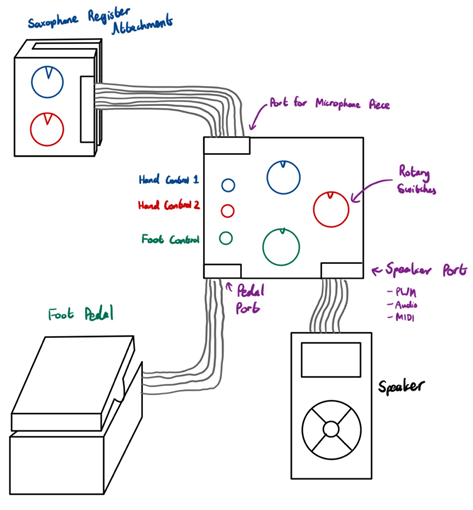
Selmer-Style Varitone
Rather than fitting for a specific type of saxophone, I hope to make mine adaptable for all of my instruments. It will include an attachment device, fit for various instruments I play, with a microphone and hand-accessible dials for speaker control, a Long & McQuade amp or speaker, a control pedal for when hand control isn’t viable, and a main circuit forming the various connections between audio sources and MIDI devices. Any operating Varitone will have three or four devices: an attachment, a main circuit, a speaker, and possibly a pedal. I hope to 3D print most of the devices like the instrument attachments, but I plan to do some wire tinkering with guitar pedals to make use of their existing circuits. The internal circuit of each device will be housed on a THT PCB, and controlled by either a microcontroller or older devices that were used within varitones. My varitone will have some of its historic capabilities such as sound distortion, modified vibrato, pitch dampening, and octave-wide intervals. I hope to add capabilities such as imperfect intervals, pitch bending (scoops, falls, lifts, drops), fine tuning, and volume control.HARDWARE 328P SOFTWARE C DESIGN PCBs for each device’s circuit. 3D printed cases for the instrument attachment devices and the main circuit. Cables for each device’s connection. COMMUNICATION Wired Communication, if necessary. I2C preferred if so. MECHANICAL N/A |
Short ISP Choices
ISPs are gifts. The best choice for you is the one that fits well with your interests, as well as strengths, and blows the doors of your future opportunities wide open!
It takes CONSIDERABLE time and reflection to make the BEST ISP choices but, the good news is that this year you have more options than ever before. For the 2022/2023 ICS4U-E year, the starting point for your Short ISP could come from any of the following areas (no group projects and no duplications),
 As you wind up the final two terms of your secondary education it is time to both advance and lock in your burgeoning engineering skills. Whereas through-hole technology (THT) has had a good run over the past few decades, the future is Surface Mount Technology and Design. For this reason, you best be prepared. This ISP round you will refine your SMD and CAD skills to showcase your Design skills in preparation for the opportunities that await you in the next few years.
Your Medium ISP goal (20% of your final mark) should include the slimmest of useful DES devices consisting of a custom PCB, populated with SMT parts, and encased or hosting (Truth Be Told, Mastermind) 3D printed components in the thinnest form possible (think wallet-size proportions). You have two months. Our 3D Printing TAs, and either JLCPCB or DirtyPCBs are all about to get a serious Sr. ACES workout.
Should you be stuck for a meaningful project, consider a DDPv7 Legacy Shield to complement or replace the ones we already have (Intersection, ADC, Universal v1 or Universal v2). The only stipulation I impose is that these devices must remain compatible with our current EAGLE DDPv7/Shield files.
Download and review the updated Medium ISP Proposal. This Word version I would ask that you edit, attach, and email on Saturday January 14, 2023 under the Subject Line: Medium ISP Proposal.
Long ISP (THT and/or SMT, Fixed or Flex)
 Download and review the updated Long ISP Proposal. This Word version I would ask that you edit, attach, and email to on Monday February 21, 2022 under the Subject Line: Long ISP Proposal.
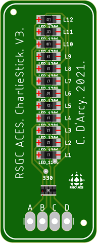
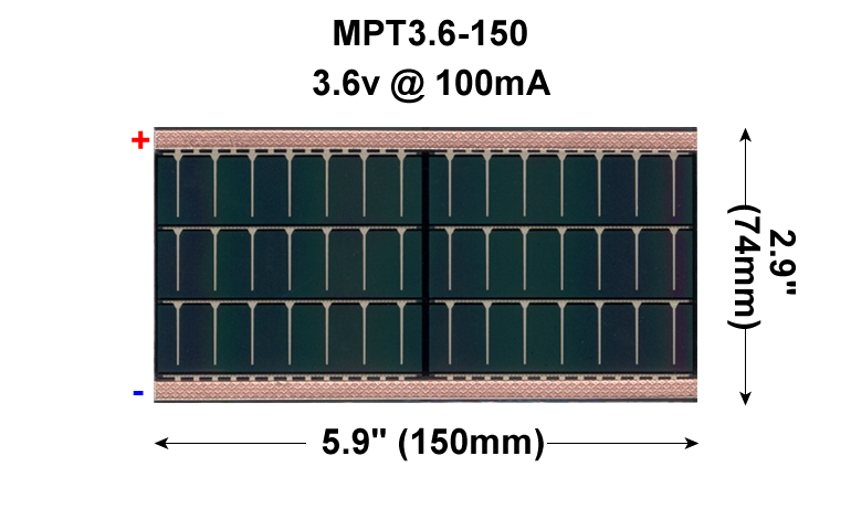
Electronic control over your final ACES ISP must be in the form of custom PCB populated with either through hole and/or surface mount components. In the case of the latter, you can consider taking your design to the next level, in the form of a Flex circuit that will be laminated into a page of your DER. If your circuit proves fully functional a flexible 3.5V, 150 mA Powerfilm solar cell will be included in the lamination so that that viewers of your creativity will marvel at when shown the light of day!
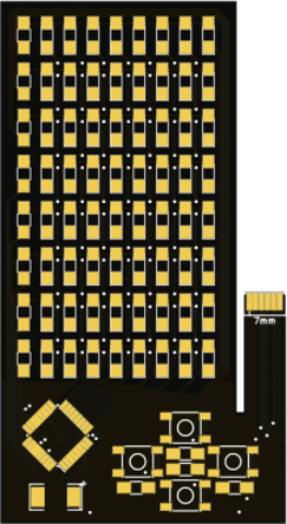
![]() The Flex Circuit concept was first introduced into the ACES curriculum in the 2015/2016 TEI4M year with some impressive results. Where the attempts since have failed is whren the designer becomes too ambitious. If you choose this route, I require that you keep it SIMPLE. (LEDs and resistors only?) Your Medium ISP requirements provided you with valuable experience that should improve your likelihood of success as will be a small project this term that requires the use of the ACES ATtiny85 SMD Trainer. The examples below are too ambitious for us but each offers a unique feature you may wish to consider,
The Flex Circuit concept was first introduced into the ACES curriculum in the 2015/2016 TEI4M year with some impressive results. Where the attempts since have failed is whren the designer becomes too ambitious. If you choose this route, I require that you keep it SIMPLE. (LEDs and resistors only?) Your Medium ISP requirements provided you with valuable experience that should improve your likelihood of success as will be a small project this term that requires the use of the ACES ATtiny85 SMD Trainer. The examples below are too ambitious for us but each offers a unique feature you may wish to consider,
For the bulk of your formal education you have been, and will continue to be, required to consume curriculum chosen for you by someone else. Fortunately (hopefully) you will put this knowledge and skill to good use in your future. However, jumping through someone else's hoops alone does not, typically, secure future success. For that, you must demonstrate your own initiative, motivation, and passion. These qualities need to be cultivated and our Grade 10 hardware course is a perfect place to start. There is so much to learn and there are so many great projects out there that offer stimulating contexts within which to develop and refine your interests.
| Grade | Contribution to Final Mark |
|---|---|
10 |
30% |
11 |
50% |
12 |
60% |


