| ICS4U-E Tasks |
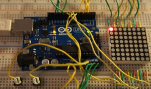
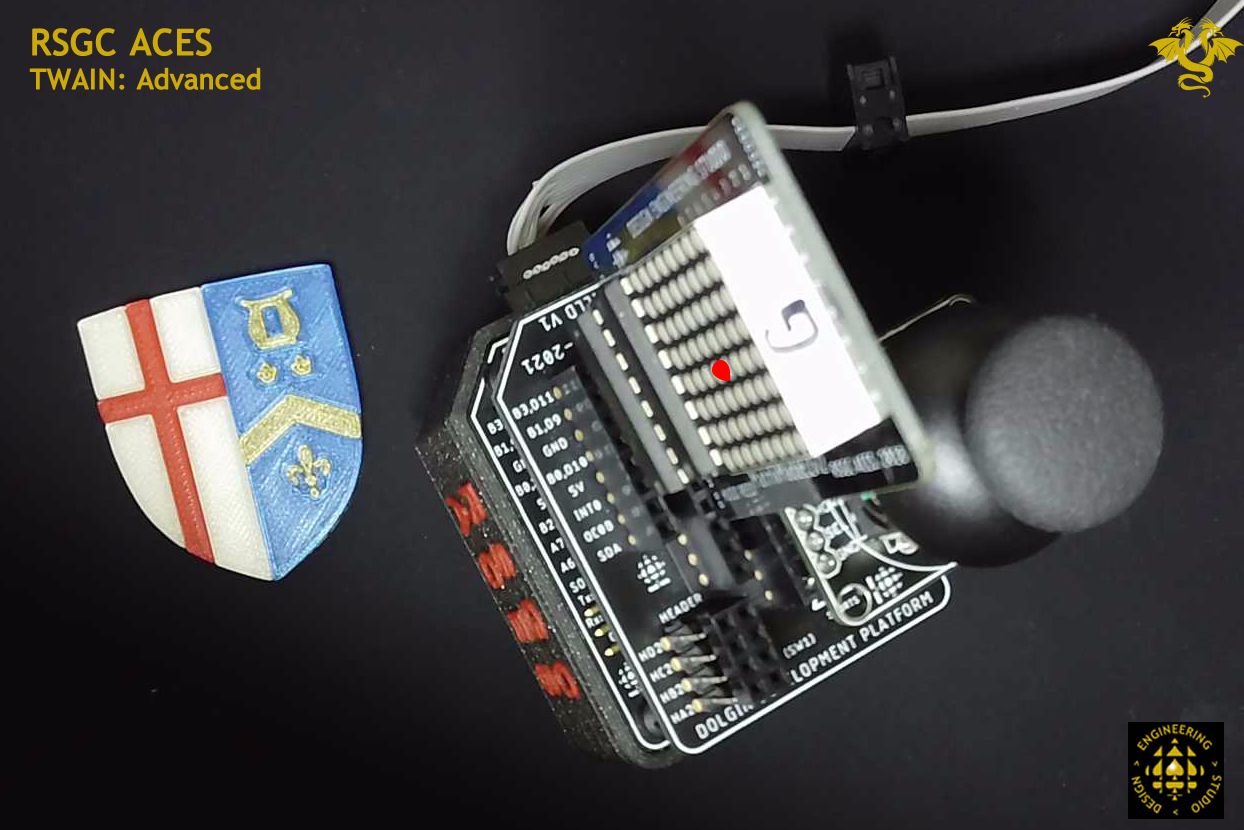
![]() Project 3.5. TWAIN (Task Without An Interesting Name). For your first (only?) AVR Assembly project on your DDBv7 you are asked to manipulate the position of a single LED on an ACES display device through the use of an analog input device. To provide a better fit for your software skill set I'm giving you a choice between one of two options. Please choose the one that is better suited to your abilities. You'll get more out of the exercise this way.
Project 3.5. TWAIN (Task Without An Interesting Name). For your first (only?) AVR Assembly project on your DDBv7 you are asked to manipulate the position of a single LED on an ACES display device through the use of an analog input device. To provide a better fit for your software skill set I'm giving you a choice between one of two options. Please choose the one that is better suited to your abilities. You'll get more out of the exercise this way.
INPUT. Your trusty blue 10 kΩ trim pot can be inserted as an appliance into any number of positions within the DDBV7's female headers. Alternatively, a Thumb Joystick offers two perpendicularly arranged potentiometers that can support X-Y positioning. An RSGC ACES Thumb Joystick breakout board enables the use of the joystick as a DDBv7 appliance.
OUTPUT. An ideal location on the DDBv7 for your familiar RSGC ACES Morland Bargraph (T. Morland ACES '18, Queen's 22) has been provided offering 1-Dimensional access (X) to 8 LEDs through the support of a '595 shift register. The RSGC ACES MatrixMadeEZ (H. Reed, ACES '19, Queen's '23) offers 2-Dimensional access (X-Y) to 64 LEDs through the support of a '595 shift register and TPIC595 (Power) shift register. To achieve 'appliance' status for the Matrix Made EZ a Universal Shield V1 is required. See Mr. D for this.
| TWAIN: Basic (1D) | TWAIN: Advanced (2D) |
|---|---|
 |
 |
Task.
![]() Project 3.4. Pin Change Interrupt
Project 3.4. Pin Change Interrupt
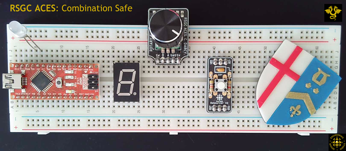
 Create the project CombinationSafe. (or MyLocker?)
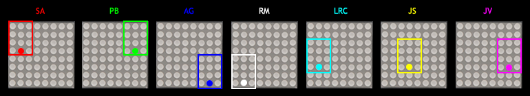
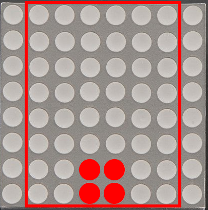
![]() Project 3.3. Keypad Matrix Echo. For your first ATtiny84 project of ICS4U you are to maximize your mid-level coding skills in the development of a prototype that echoes button presses on your 12-key telephone keypad onto your small Adafruit 861 8x8 matrix. Each of you has been assigned a 4x3 subset of your matrix as shown below that represents the 1:1 Key→LED mapping. For example, should your user press the '0' key, the LED indicated will light up for 300 ms, only.
Project 3.3. Keypad Matrix Echo. For your first ATtiny84 project of ICS4U you are to maximize your mid-level coding skills in the development of a prototype that echoes button presses on your 12-key telephone keypad onto your small Adafruit 861 8x8 matrix. Each of you has been assigned a 4x3 subset of your matrix as shown below that represents the 1:1 Key→LED mapping. For example, should your user press the '0' key, the LED indicated will light up for 300 ms, only.
Your ATtiny84 has just enough GPIO pins (10) to pull this task off as I describe it below (7 input; 3 output). Furthermore, the code is surprisingly short if done skilfully.
(Basic) Task.
 Optional (Advanced) Task.
Some of you may wish to consider going beyond the basic task.
Rather than 1:1 Key→LED mapping, a 1:4 Key→LED mapping could be achieved. What is compelling about this implementation is that it requires a skill you already possess: PoV!
You have the time; consider it if you are inspired.
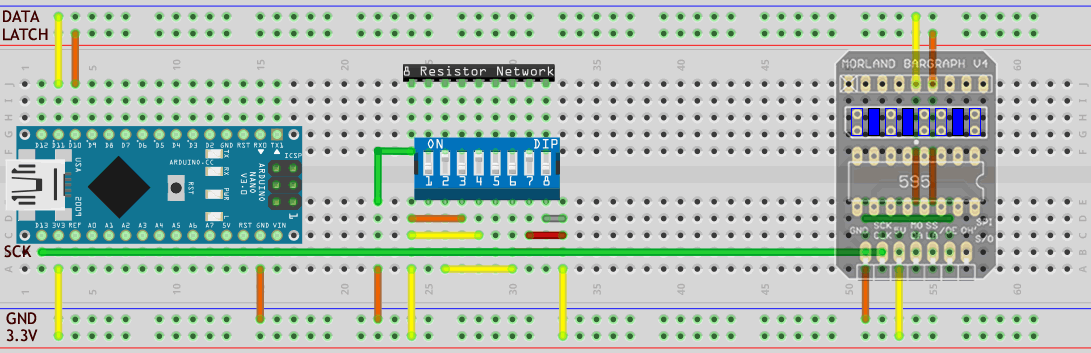
With efficient register level shiftout functions seamlessly accessible to your future projects, it is an opportune time to examine a similar optimization for input. This project exploits single statement input of the full byte-state of an 8-position rocker switch. For confirmation you will echo the input on your 8-LED Morland Bargraph V4.
The ability to read the state of 8 switches with a single statement provides the ACES Binary Challenge and other applications with increased efficiency. In the partially wired prototype below it is easy to imagine that continuous echoing of the state of the rocker switches on your MBV4 can be achieved with just two lines of caller code.
Task
If you have the motivation, curiosity, and time this week you are encouraged to consider developing an emulation of the ACES' Binary (Unsigned) Challenge in which random unsigned byte values (in decimal) are presented on either an LCD, OLED, or multiple 7-Segment displays, for example (the Serial Monitor is likely not an option in this project as we need all 8 bits of PORTD for input). You are awarded credit for providing the correct response, in binary. The points are 30 (if you answer in less then 10 s), 20 (if you answer in less than 20s) , and 10 if you eventually enter the correct value at any time before the 5 minute time limit expures.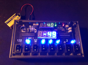 Create the Arduino Nano project, BinaryChallenge.
![]()
![]() Project 3.4 Register Level Shiftout
Project 3.4 Register Level Shiftout
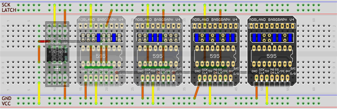
With your register level shiftout (outshift) of a single byte (uint8_t) finalized in class it is time to pair up (yes, a group project) to implement OVERLOADED register level outshift functions that will accomplish the same for uinti16_t, and uint32_t integers. Our recently developed ACES Morland Bargraph V4 is an ideal vehicle to test and display the results as it breaks out the 595's Carryout pin to enable chaining. The graphic below suggests a prototype wiring strategy. Click to enlarge.
 ACES' Optimization considerations include an efficient means to reuse code such as your effective register level outshift() function. The natural question that arises is, "How best to make use of previously developed stable coding assets in future projects?". We could certainly 'copy and paste' the code into every new project but that has drawbacks. For example, what if we want to modify the code at a later date? We'd have to hunt down every previous copy of the asset and edit and test. Surely a better solution would be to maintain ONE version of the asset and place it in a location that is accessible from every new project we create. This project will achieve that by introducing you to the concept of a personal code library.
Task
 Feel free to collaborate with the ACE you normally sit with in class while developing this exercise.
void outshift(volatile uint8_t *port, uint8_t dat, uint8_t clk, uint8_t dir, uint8_t valu){

void outshift(volatile uint8_t *port, uint8_t dat, uint8_t clk, uint8_t dir, uint16_t valu){

void outshift(volatile uint8_t *port, uint8_t dat, uint8_t clk, uint8_t dir, uint32_t valu){
 Create a new folder called ICS4U23 within the \libraries folder of your Arduino sketch folder
void shiftOut(uint8_t dataPin, uint8_t clockPin, uint8_t bitOrder, uint8_t val) {
  uint8_t i;
  for (i = 0; i < 8; i++)  {
    if (bitOrder == LSBFIRST)
      digitalWrite(dataPin, !!(val & (1 << i)));
    else
      digitalWrite(dataPin, !!(val & (1 << (7 - i))));

    digitalWrite(clockPin, HIGH);
    digitalWrite(clockPin, LOW);
  }
}![]() Project 3.3 Gate-Level Minimization
Project 3.3 Gate-Level Minimization
TBD
![]() Project 3.2. CHUMP. See here.
Project 3.2. CHUMP. See here.
![]() Project 3.1. SMT: PB Machine. One of the greatest challenges (and I believe, privilege) for ACES is to influence the direction of our program. Through your imagination and skill you are expected to contribute to the enhancement of our mutual creativity, tool set, and assets.
Project 3.1. SMT: PB Machine. One of the greatest challenges (and I believe, privilege) for ACES is to influence the direction of our program. Through your imagination and skill you are expected to contribute to the enhancement of our mutual creativity, tool set, and assets.
P. Bagga (ACES '17, UofT '22) fulfilled this opportunity/commitment when he decided he could improve on the DC Breakout Board ACES were using by adding a simple Resistor/LED power indicator using small 1206 size SMT components. Click on the image to the right of the (affectionately called) PB Machine for a more thorough explanation of its design. Apart from its functionality, this PCB offers a perfect introduction for Sr. ACES to practice the hand-soldering of SMT 1206 parts.
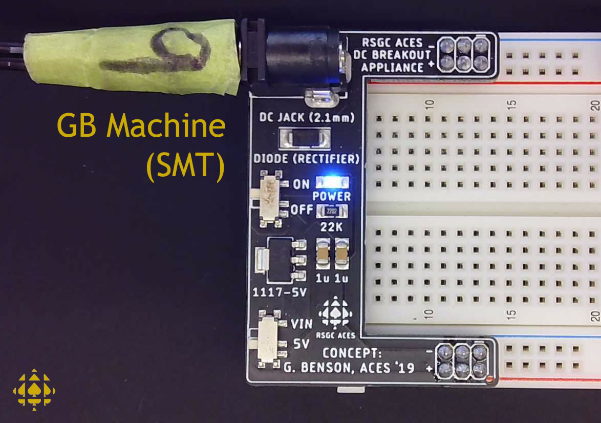
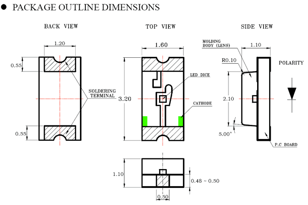
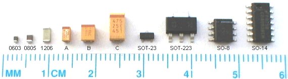
G. Benson (ACES '19, Calgary '24) also met this challenge with the enhancement of the indispensable PB Machine (P. Bagga, ACES '17). In the Fall of 2019 and 2020, Sr. ACES had the opportunity to solder up their own GB machine and put it to good use in the pursuit of their own prototypes. In the 2021/2022 year ACES benefit from JLCPCB's relatively inexpensive SMT Assembly Service requiinrg only additional THT soldering. Your experience with electric circuits has been largely limited to components that use through-hole technology (THT). To round out your proficiency with all components, your next few projects will require the use of devices that use surface-mount technology (SMT). As the graphic reveals, the smallest size that is reasonable for hand-soldering techniques is the 1206 family, so this is what we carry in the DES inventory. Update: By the Spring of 2021, ACES had shifted their skill set to the SMT Design and (reasonably-priced) Assembly of PCBs to JLCPCB. Increasing dependency on outsourcing may not be the wisest decision in the long run but, in the short run, it remains an option. You will be provided with a newly designed and fully assembled SMTV1 GB Machine to serve for both function and inspiration.
GB Machine (click image to enlarge) |
1206 LED Package |
|---|---|
 |
 |
Task.
