 Our initial session justifiably begins with an emphasis on tips and techniques for writing GREAT code. The months (years?) of software development ahead of you are best served by first acquainting yourself with fundamental coding concepts applicable to ALL software contexts. At the very least, the size of the DER space occupied by your project report's Code Section will be optimized.
The motivational brilliance behind the development of the Arduino hardware platforms included providing curious and creative minds with straightforward,, seamless access to the power of electronics based on the (AVR) microcontroller. The Nano is one such development board that breaks out the functionality of the AVR ATmega328p to a breadboard-compatible form factor. Click on the image to the right of Version 3 and acquaint yourself with as many of its resources as possible, for now. Take your ABRA Nano from your kit and compare your findings.
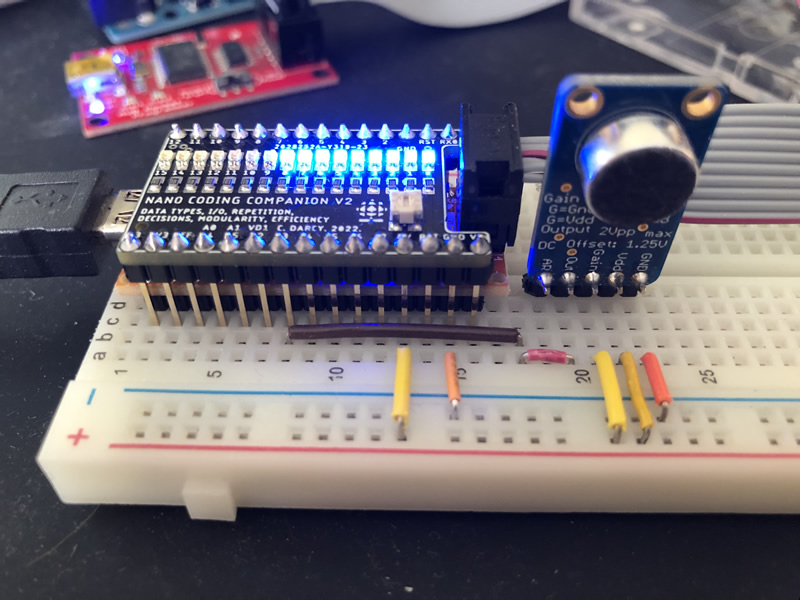
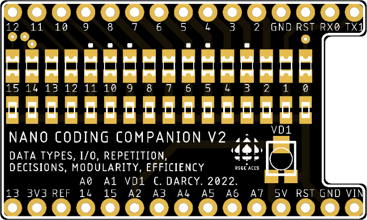 To place an emphasis squarely on software from the outset of our course, a Nano-compatible breadboard appliance was developed in the Spring of 2022 for ICS3U-E ACES to focau and sharpen their coding skills. After inserting the Nano into your breadboard, position your Nano Coding Companion PCB over top of the Nano. As a 'breadboard appliance' no additional supporting wiring is required to explore the basic coding concepts below of data types, input/output, loops, decisions, modularity, efficiency and documentation. On the output side, the NCC breaks out 16 of the ATmega328p's digital pins (0-15) to blue SMT 0805 LEDs. For input, a Bourns SMT 5 kΩ Trimpot (JLCPCB Part #C124626) provides variable voltage into Analog Input pin 2. For the exercises to follow on this page the Nano is best programmed with your Sparkfun AVR Pocket Programmer.
Finally, you 'may' wish to add these two statements at the start of your setup() function: DDRD = 255; PORTD = 0;
Additional Coding Skill Development: Towards Better Code
1. Blink. Modify the Examples > Blink sketch to achieve the following result on your NCC.
2. BlinkPlus. Load your Template sketch and Save As BlinkPlus. Adapt the code to achieve the following result on your NCC as efficiently as possible, given what you know.
3. Bars. Load your Template sketch and Save As Bars. Achieve the following result on your NCC.
4. Bars Decreasing. Achieve the following result on your NCC. For your first iteration, hard code the delay between frames to be 200 ms. After successful completion if this first interval, allow the user to control the speed of animation through the manipulation of the onboard pot.
5. Random. Achieve the following result on your NCC so that any one of the 16 onboard LEDs will be on, one at a time, for a duration of 2 s.
6. Fade In. The pins marked with green dots (see the Nano image at the top of this page) support (limited) PWM through the use of the analogWrite(pin, duty) function. Achieve the following result on your NCC in which a complete fade in cycle occurs every 2 s (approximately).
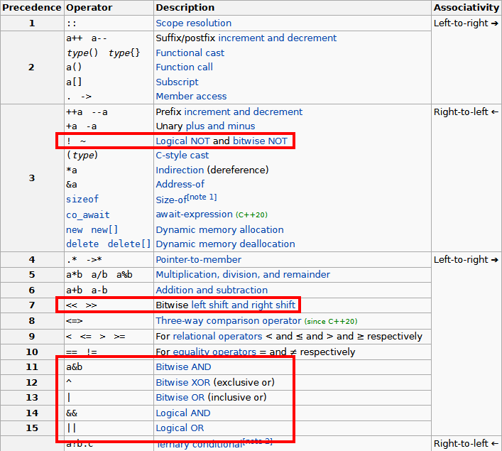
Subsequent exercises focus your attention on the similarities, differences, and subtleties of C++'s logical and bitwise operators.
Complete list of C++ Operator Precedence
 7 b.
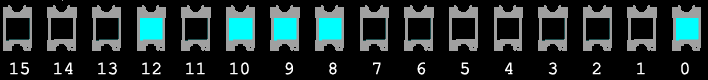
7 b.  BinaryCounting. You will recall Stage D of last year's Counting Circuit that presented 4-bit binary counting as output from the CD4516 Binary Up/Down Counter IC. In this exercise you will develop a program that will exploit your NCC's 16 LEDs to present 16-bit binary counting! This results in 216 = 65,536 different states, of which 0x1701 in 10 a was but one state.
Now, the key to this is a for loop within a for loop, a structure referred to as a NESTED loop. An animated gif of the entire sequence is, understandably, not practical.
8. Analog In/Digital Out. This is a two-task exercise.
- Adapt the previous code to include the display of the analog reading (a uint16_t variable) on the LEDs.
- Use this 10-bit ADC reading to determine whether to turn LED 15 ON (≥ 2.5V) or OFF (< 2.5V).
9. Digital In/Digital Out. Achieve the following result on your NCC by performing a digital read of your onboard pot (A2) and echoing the result through a digital write on pin 15.
10. Analog In/Analog Out. In this exercise, without the benefit of an animation, perform the following, continuously,
- Obtain a 10-bit ADC reading of the onboard pot,
- Reuse code from the previous exercise to display the 10-bit reading on digital pins 0-9, and,
- (Efficiently) scale/map the ADC reading to its 8-bit equivalent, using this as the duty cycle parameter for an analog write to pin 11.
11.  EEPROM. Successful completion of the previous uint16_t exercise opens the door to this insightful and creative project. (Note: You will need your standard cable (AVR ISP) to complete this exercise. Your AVR Pocket Programmer appears incapable of accessing EEPROM correctly)
Your AVR MCU has three memories: Program Flash, SRAM and EEPROM. The first and last are non-volatile meaning their contents are preserved even when the power is disconnected. In this exercise you are asked to write, read, and display the contents of EEPROM as an animation.
To get you started, I have prepared a sketch to populate EEPROM with the data for the animation. Download and review the sketch, EEPROMWrite.ino, before uploading it to your Nano. Launch the Serial Monotor and compare the output to the C code itself. By looking at the array data, you may be able to imagine what the animation will look like when you finally finish the EEPROMReadandDisplay.ino code that will continually play the animation on your Nano Coding Companion!

12. Complement. The inverse of a bit is also referred to as its complement. Thus, the complement of 0 is 1 and the complement of 1 is 0. In terms of logic gates, this is the result of applying the NOT operator. Save the previous exercise to a project named Complement and adapt it to achieve the animation below.
13. Operators: Logical vs Bitwise. After consideration of class discussions on the matter and reviewing the operators and their relative order of precedence (above), predict the value of the result variable for each expression below. Run and confirm your predictions on your NCC.
void setup() {
  //set first 16 digital pins to output...
  for (uint16_t pin = 0; pin < 16; pin++) {
    pinMode(pin, OUTPUT);
    //    digitalWrite(pin, LOW);
  }

  uint16_t a = 7 << 13;
  uint16_t b = 192 >> 3;
  uint8_t c = 16;

  uint16_t result;
  result = a;
  // result = b;
  // result = a | b | c;
  // result = a | b & c;
  // result = a || b && c;
  // result = ~a;
  // result = !a;
  // result = !!a;

  // provide LED representation of word-size data
  displayWord(result);
}
/***************************************************************************
   Purpose: LED display equivalent of binary representation of the parameter
   PreCondition: 16 I/O ports declared for output
   PostCondition: NCC's LEDs provide binary representation of the parameter
 ***************************************************************************/
void displayWord(uint16_t data) {
  for (uint16_t pin = 0; pin < 16; pin++)
    digitalWrite(pin, data & 1 << pin ? HIGH : LOW);
}

void loop() {}
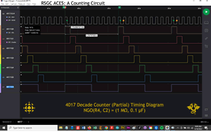 14. CD4017. Remember your Counting Circuit from last year? The clock signal ouput of the NGO was presented to the 4017 Decade Counter. The rising edges of the clock signal input resulted in the 4017 presenting a cyclical firing of its 10 output pins. Its 'Divide-by-10' pin completed one cycle at one-tenth the frequency. This behaviour is captured in the adjacent image from our Logic Analyzer.
In this exercise, duplicate the standard 4017 behaviour on your NCC as suggested in the animation below.
For thr curious, here's another application of cascaded 4017's, resulting in this effect.
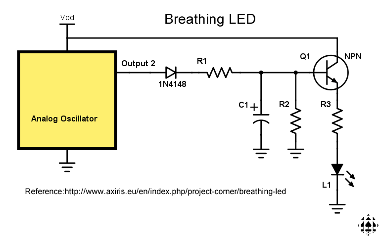
15. Breathing LEDs. The brightness of an LED is dependent on current. This feature is easily manipulated in hardware by changing the size of the series resistor. Another hardware design to affect current changes is presented in the circuit (below, right, that appeared in your Grade 10 DC Circuits workbook. This application of the Analog Oscillator (aka Astable Multivibrator) circuit emulates a 'breathing' cycle. The square wave(ish)' output of the oscillator supports the charge/discharge action of an RC pair that drives the base pin of an NPN transistor to control current, resulting in the fading in and out of an LED. This year, we explore a similar software-based simulation on the NCC.
| Breathing LED Circuit |
PWM: Duty Cycle |
 |
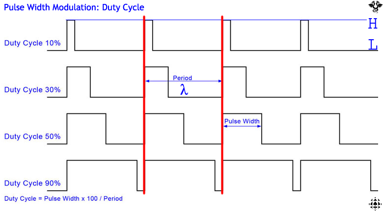 |
First off, an alternatve to current-controlled LED brightness is to exploit the human eye's persistence of vision characteristic. If an LED is turned on and off repeatedly our eyes will interpret brightness levels in direct proportion to the on/off time ratio. More precisely, in the world of digital signals, it is the ratio of ON time to the total of ON and OFF time (period) that is the key. This is referred to as the duty cycle. For example, if an LED was turned ON for 9 ms and OFF for 1 ms, repeatedly (90% duty cycle), the human eye would perceive the LED to be brighter than if it was ON for only 1 ms and OFF for 9 ms (10% duty cycle).
As you are now aware from earlier exercises, the ATmega328P (Nano and UNO) offers 6 pins capable of Pulse Width Modulation (PWM) in which a square wave of fixed frequency can be easily produced through the use of Arduino C's analogWrite(pin, duty); function. With a little more thinking it should be apparent that any MCU digital I/O pin can produce a square wave of varying duty cycle AND frequency simply by turning them ON and OFF for various durations.
Develop the sketch Breathing.ino that results in ALL 16 LEDs fading in and out, in unison, at a rate that reflects human breathing, similar to the animation below.

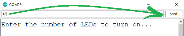
16. Serial Input. Earlier NCC exercises (Analog In/Digital Out, Digital In/Digital Out) supported user control over the NCC's output. This third example introduces you to a more versatile option for digital input through the use of the Arduino's Serial Monitor.
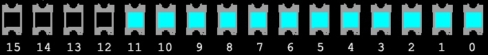
Develop the sketch SerialInput.ino that requests the number of consecutive NCC LEDs to be turned on (through the Serial Monitor) from the user as shown below, before lighting them.
Question. What steps must be undertaken to get this to function correctly and why?
17. VU Meter. This stage was inspired by this video: https://www.youtube.com/watch?v=ogcEquL6oUE

