2022-2023 ICS4U Independent Study Projects (ISPs) |
![]() Independent Study Projects. Please read our overview on why ACES pursue Independent Study Projects so vigorously.
Independent Study Projects. Please read our overview on why ACES pursue Independent Study Projects so vigorously.

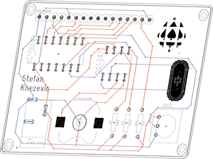
 To my mind, the characteristics of a great project include such aspects as imagination, creativity, a degree of risk and, sometimes, even simplicity, to name a few. Check out the flashlight circuit 'board' this guy made out of little more that a piece of paper and a pencil? Simple, but inspiring.
Consider a problem that needs a solution. Boyan Slat did at age 17 when he was in high school; four years later he is
To my mind, the characteristics of a great project include such aspects as imagination, creativity, a degree of risk and, sometimes, even simplicity, to name a few. Check out the flashlight circuit 'board' this guy made out of little more that a piece of paper and a pencil? Simple, but inspiring.
Consider a problem that needs a solution. Boyan Slat did at age 17 when he was in high school; four years later he is Also, don't underestimate the value of an enterprise/entrepreneurial aspect to your project that could see a number of units of your project in the hands of future ACES, for sale in the Dragon's Lair or beyond, reaching an even a broader audience.
| ACE | Short ISP (20%) Saturday September 17 |
Medium ISP (20%) Saturday January 14 |
Long ISP (20%) Saturday April 1 |
|---|---|---|---|
| Proposals >>> | Short ISP Proposal | Medium ISP Proposal | Long ISP Proposal |
Appleyard, S.
|
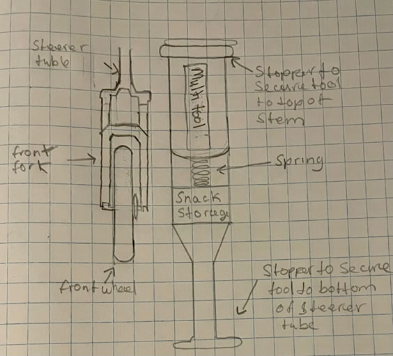
Bike Tool Carrier
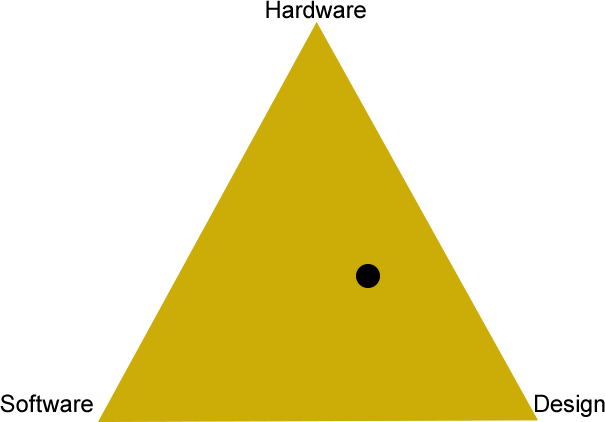
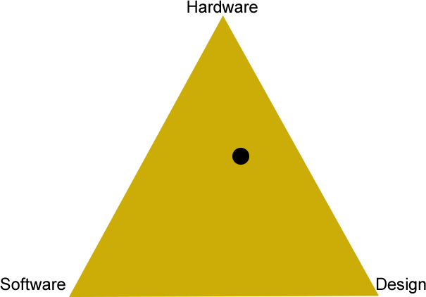
HARDWARE N/A SOFTWARE N/A DESIGN THE TOOL HOLDER FOR THIS PROJECT WILL BE DESIGNED IN FUSION 360 AND TESTED THROUGH MANY ITERATIONS AND REVISIONS. COMMUNICATION N/A MECHANICAL N/A |
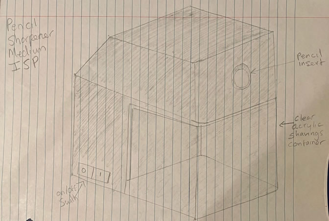
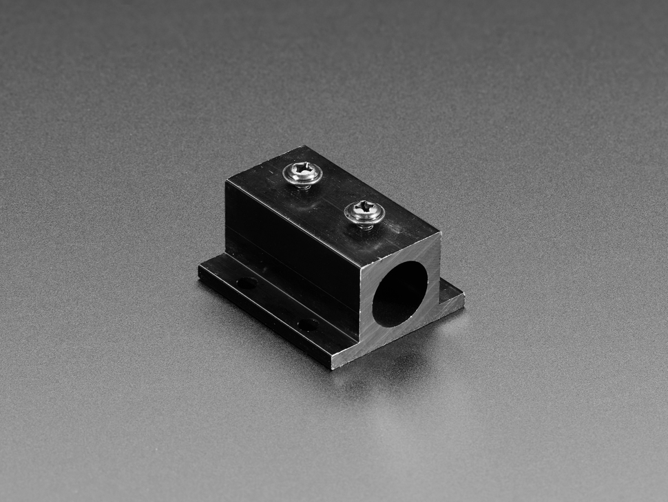
Electric Pencil Sharpener
DESCRIPTION While modern pencil sharpeners offer an easy and efficient method to sharpen most pencils, they are usually too underpowered to sharpen tougher wax pencils. The electric pencil sharpener that I will make for this project will contain a more powerful motor and sharpening head to deal will the added strain. The sharpener will have a clear acrylic shavings container below the pencil sharpener body to hold the shavings. |
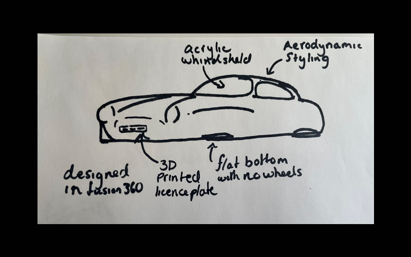
Car Body Design (with 'Features)
DESCRIPTIONWhile all of my ISPs to date have ended with a working product, the goal of this project is to learn how to work with curves in Fusion 360 with the end goal of designing a car body similar to a Mercedes Benz 300sl Gullwing or a 1970s Porsche 911, both containing iconic aerodynamic designs around the headlights. The car will also have acrylic front and rear windshields as well as 3D printed license plates. |
Appleyard, T.
|
ACES Tool Box
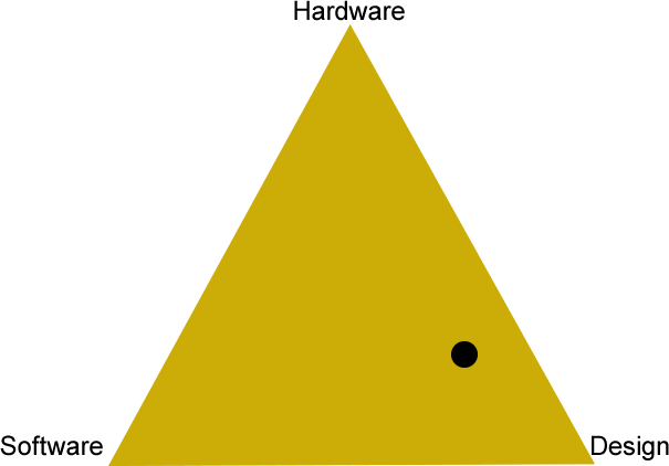
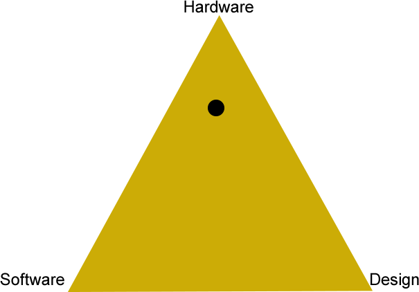
HARDWARE N/A SOFTWARE N/A DESIGN This project will make use of fusion 360 and potentially on acrylic lid to be able to see through to see all of your parts in the top. COMMUNICATION N/A MECHANICAL Hinges? Minimized friction? |
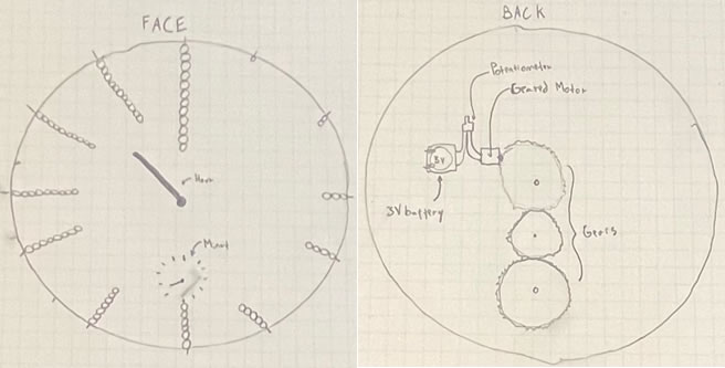
Appleyard Fully Analog Clock
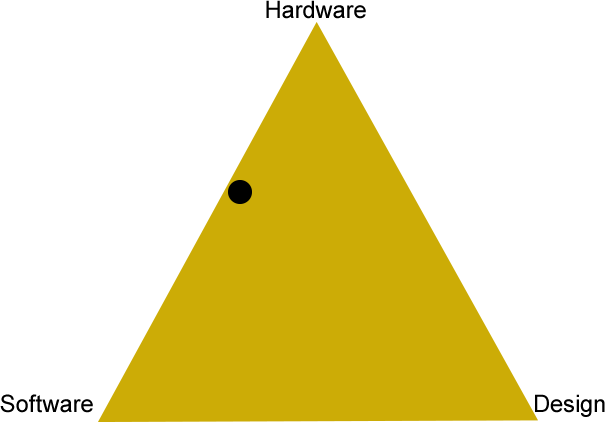
HARDWARE Gears of some sort... SOFTWARE N/A DESIGN For the design part of this project, the clock body will be designed in function 360. It will either be 3D printed, or CNC Milled out of aluminum. The rest of the clock is made up of a series of 3D-printed gears, as well as two 3D-printed hands. I may also choose to display the date on the clock. COMMUNICATION N/A MECHANICAL The hardware portion of this project will involve a few key parts. It will have a small geared 3 volt motor powered by a coin battery. This motor will have an on off switch as well as having its speed regulated through a potentiometer. All of this will be managed on a PCB designed in Easy EDA. |
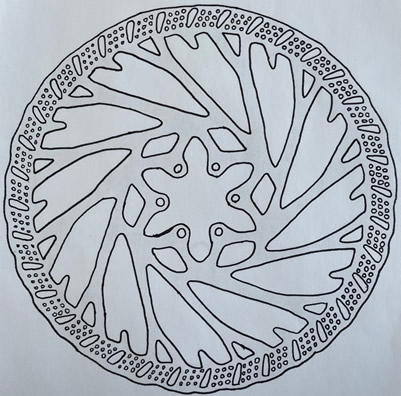
Appleyard M. Bike Disk Break Rotor
DESCRIPTION Throughout my time in this course I've enjoyed all of my ISP’s, but the ones I have enjoyed the most have been the ones that have focused on design. for my final ISP at RSGC I wanted to do one that was entirely designed but that also solved the problem. With this information in hand I have decided to design and build using either CNC milling or laser cutting a mountain bike brake rotor that both dispersed heat well, looked good and was affordable. This will be designed in Fusion or Adobe Illustrator and made out of aluminum. aluminum has been chosen because it is highly conductive meaning that when the break is heating up under friction it will not retain its heat. |
Elder, A.
|
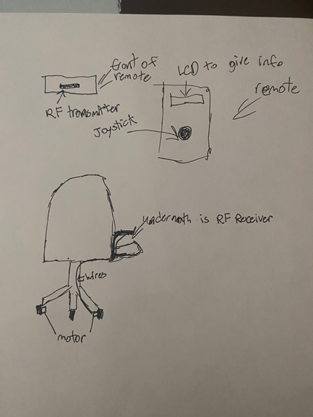
Motorized Chair
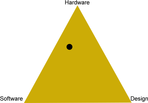
HARDWARE I will use a atmega328p which will be used for the joystick on the remote and sending and receiving the RF signal SOFTWARE Arduino C: I will write code to be able to read the joystick outputs and be able to transmit them to the motors. DESIGN I will make a 3d case for my JLCPCB PCB which will have my joystick on it and the RF transmitter. COMMUNICATION I will us RF to transfer the data between the controller and the motors. MECHANICAL I will use (???) motors to move the chair. |
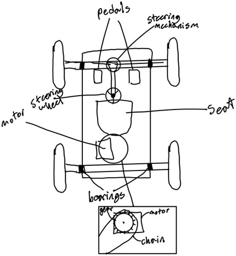
Go-Kart
HARDWARE For the hardware part of this PROJECT, I will be using many mechanical parts to make the wheels spin. for example, I need to make the front wheels able to turn from a steering wheel which will need a mechanical system. I will also need gear shafts to be able to send the motors rotational torque to the wheels that are on the front and back of the go-cart. SOFTWARE There is no coding needed for this build and I have chosen this project to have none since I am comfortable with coding more than hardware and design. DESIGN I am using design to build the go-cart and how it will look. I will also need it to design where the seat, motor and pedals sit on the go-cart. COMMUNICATION N/A MECHANICAL Seriously? You need to ask? |
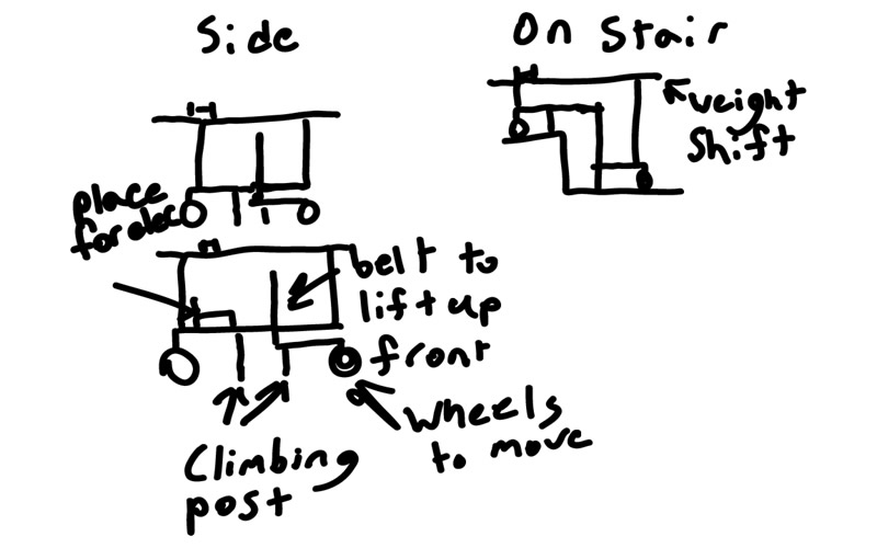
Elder Auto Stair Climber
DESCRIPTION The Elder Auto Stair Climber will be able to go up any size of stairs and this will be done by its ability to sense the next stair in front with two sensors on the front of the Climber. It will also have wheels that will allow it to move itself to the set of stairs wanted and then climb. |
Mann Shaw, H.
|
Switch Mode Bench Power Supply
HARDWARE The 328P that I plan to use in this project will not have a huge number of roles, but it will aid in reading and displaying the current and voltage. If fans are required, it will also control them. SOFTWARE Arduino C: Since this is not a primarily software project, and I am more interested in hardware/electrical engineering/physics, I plan on just using Arduino to code my LCD and to read the current and voltages from my sensors. To focus largely on the other parts of my project, I will likely use the LCD library, and no library will be necessary to read the measurements from my sensors or to control power to fans. DESIGN I plan on designing a PCB for the entire SMPS, and will likely use stripboard for the sensors and ATmega328P circuit. I will design the PCB on Eagle and will order it through JLC. The PCB will be THT soldered parts unless there is a need for me to make some of them SMT. Like I mentioned, I plan on designing 2 3D printed cases, and I will do this through Fusion360. These cases will be designed to perfectly fit the LCD display as well as the input, and output power cable adapters. COMMUNICATION None MECHANICAL Fans would be the only mechanical part of the project if they are used. |
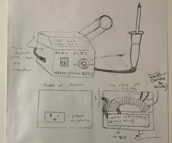
Mann Shaw Soldering Station
HARDWARE The MCU will take 2 inputs. First, it will take the potentiometer voltage input for the chosen temperature, and convert it to a temperature value. Second, it will take the voltage input from the iron which it will also turn into a temperature value. It will do this with a function that will be determined through graphing the relationship between voltage and temperature (determined experimentally). The MCU will then output the set and actual temperatures to the LCD display. It will also PWM the gate pin of the triac to control the input power to the iron’s heating element. When the real temperature is too high, it will lower the input power, and when the real temperature is too low it will raise the input. If the real temperature is correct, it will pulse the power on and off to keep the temp constant. SOFTWARE The software will simply execute the details explained in the MCU section above. It will be in Arduino C, but possibly partly in assembly depending on the feasibility. DESIGN I plan on designing a PCB on EAGLE for the driving circuit that will be ordered through JLC. Additionally, I will design a 2-part (they will fit together) 3D printed case on Fusion to house the entire project. Previous projects of mine have not been particularly pleasing for the eye, and so that will be a focus for improvement in this project. COMMUNICATION I may use I2C for the LCD, but that would be it. MECHANICAL N/A |
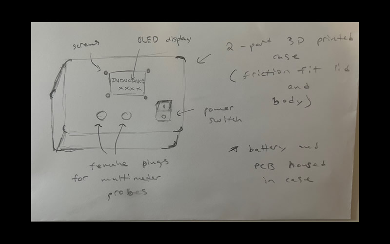
Inductance Meter
DESCRIPTION For many of my projects in the past that have involved transformers, chokes or any sort of coil winding, I would have benefitted from an easy method to measure inductance, especially for more advanced calculations. Unfortunately, the DMMs in the DES don’t offer an inductance measuring setting, and buying RCL meters online is fairly expensive. Additionally, measuring inductance requires some math and a circuit/function generator and scope, and so measuring it in the past has been annoying and difficult. Therefore, I plan to build a single function simple inductance meter so that I can measure the inductance of all the coils I have wound (and possibly fix my SMPS as the inductor might have been the problem). I plan to use an Arduino nano and a basic LC tank oscillator to calculate inductance. Essentially, LC tank circuits oscillate at the resonant frequency of the of the inductor capacitor pair. Thus, after pulsing the circuit and determining the frequency of oscillations with comparators and the nano, and with a known capacitor, the inductance can be calculated by the nano. It will then be displayed on an OLED and the whole circuit plus a battery for power will be housed in a 3D printed case. I will also use two female sockets compatible with ACES DMM probes so that inductors can easily be measured. This project is smaller than previous ones so that I have time to continue my soldering iron. |
Muir, R.
|
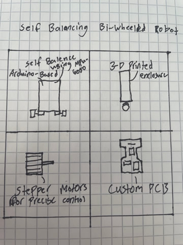
Self Balancing Bi-Wheeled Robot
HARDWARE 328P SOFTWARE Arduino C DESIGN The device will be mostly 3D printed, with the exception of a few parts such as the wheels which will need to be rubber for grip. A custom PCB will be used in order to save space COMMUNICATION N/A MECHANICAL The device will use precise stepper motors in order to control movement. These motors are nescisarry [sic] for their arcuate [sic] positioning and quick adjusting nature. |
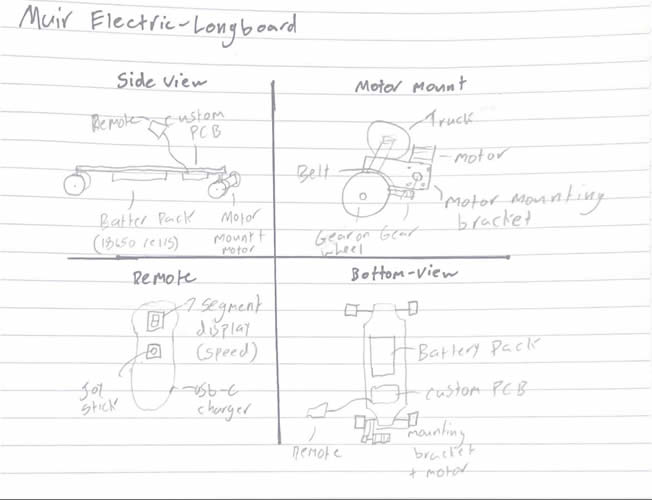
Muir Electric Longboard
DESCRIPTION I selected this project as a simple solution to the transportation problem I face in everyday life. I live close enough to the school for driving to seem wasteful, but too far to walk every day. Leaving my bike at the school is not a risk I like to take, so I needed a solution. With this device I will be able to get to school fast and on time, and leave it in my locker while in class, so I face no risk of theft. I feel like it is a challenging enough project that I can complete and optimize within the time frame given, and a good introduction into the world of CNC machining. |
Pocket Packet Sniffer
DESCRIPTION The Pocket Packet Sniffer is a portable device with an LCD screen which allows users to “sniff” wifi packets and display information about them on the screen. |
|
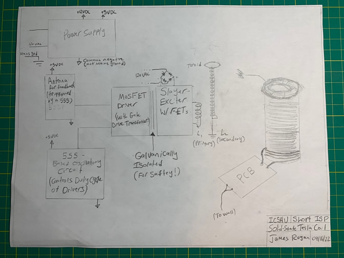
Solid-State Tesla Coil
HARDWARE ICs: 555, 3732x (1,2), 74HC14. SOFTWARE N/A DESIGN Winding mechanism and Toroid skeleton made in Fusion 360, 1 or 2 PCBs designed in Eagle COMMUNICATION N/A MECHANICAL N/A |
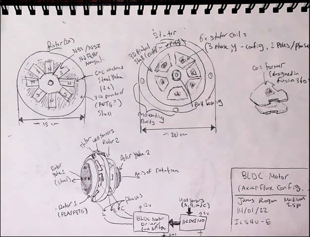
BLDC Motor
HARDWARE On the Hardware side, an Arduino BLDC (Brushless Direct Current) motor driver will be created using six MOSFETs in full-bridge configuration driven by three half-bridge drivers. Hall effect sensors will also be used for timing purposes. SOFTWARE For software, I will take advantage of the ATmega328’s built-in timing registers, as well as some high-level Arduino language, in order to send the appropriate signals to the MOSFET Drivers. I will get feedback from the motor using three hall sensors (one per phase). DESIGN The motor will be modelled in Fusion360, and from there, the required parts will be purchased / 3D printed / CNC machined. Additionally, a coil former will be created in fusion360 to allow for uniform winding of all six stator coils. The motor will use an axial-flux topology, which means the magnetic flux lines are parallel to the axis of rotation. This is an inversion of typical DC motors, which use radial-flux configurations. I chose axial-flux because it allows for a broader range of magnet shapes, saving me time and money. COMMUNICATION N/A MECHANICAL Its very essence... |
BLDC Motor Driver
DESCRIPTION The BLDC motor driver will take a wide range of voltages (approx. 15V-40V) and convert this DC voltage into three (approximate) sine waves that are 120 degrees out of phase from one another. This will mimic the EMF curves out of the three phases of the Axial Flux Alternator, enabling it to run as a motor. As is shown in the block diagram, the base circuit will consist of:
HARDWARE 328P, 6pin ISP SOFTWARE Register-Level C DESIGN Fixed PCB, THT/SMT, EasyEDA COMMUNICATION SPI MECHANICAL Reuse of Axial Flux Alternator |
Shea, E.

|
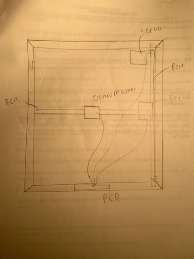
Magic Chess Board
HARDWARE 328P (Nano), Stepper Motors SOFTWARE Arduino C DESIGN EAGLE, JLCPCB, Fusion 360 COMMUNICATION Serial MECHANICAL Steppers, Servos? |
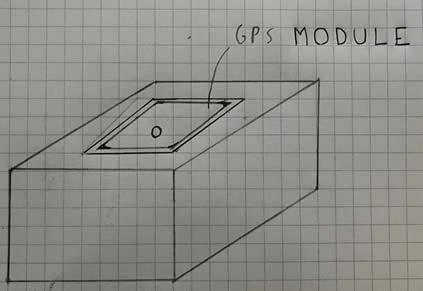
SMS GPS Tracker
HARDWARE This build will also make use of the SIM800 module as well a BN series GPS module SOFTWARE Libraries: TinyGPS++, SoftwareSerial. DESIGN There will be a custom PCB as well as a 3d printed case COMMUNICATION Serial MECHANICAL N/A |
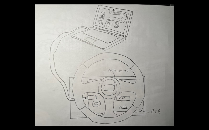
Shea Steering Wheel
DESCRIPTION This build will have aspects of all three domains, the hardware will be the circuit supporting a potentiometer that will be read to determine at what angle the steering wheel is at and send that to a computer using a USB to TTL adapter, the software will consist of two different parts, an Arduino part where the code supporting this circuit is written and a processing part where there is a simple 2D game showing the steering wheel controlling something. |
Strain, J.
|
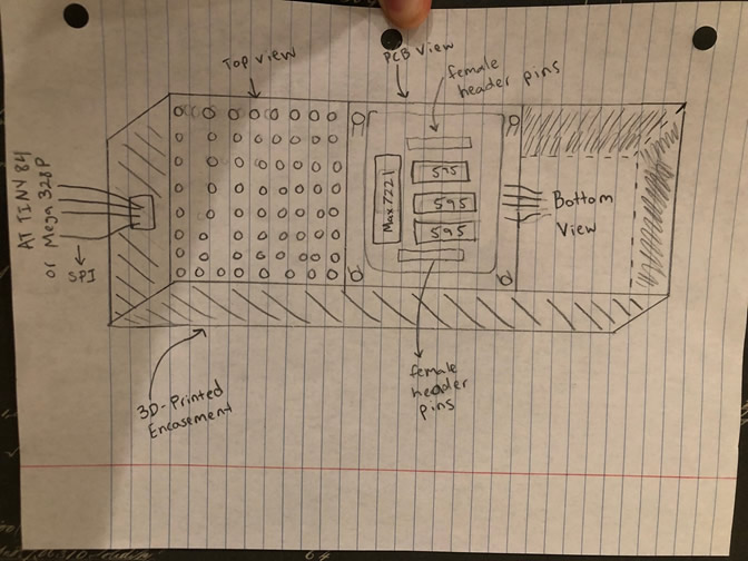
RGB Matrix Made EZ V3
HARDWARE My project will be compatible with both the 328P and ATtiny84 MCUs. SOFTWARE Arduino C, SPI Library Max72XX Lib DESIGN Eagle is the platform where i will design my PCB and i will use the services of JLCPCB for the manufacturing process. Additionally, there will be a small 3D printed encasement for matrices with an open top for easy visibility. COMMUNICATION SPI MECHANICAL N/A |
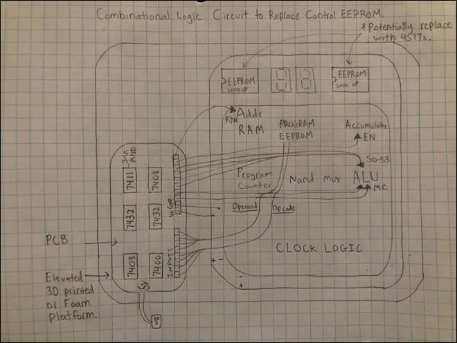
CHUMP: Control EEPROM Logic
HARDWARE I will use the 328P and the Arduino to verify my logic in software before ordering the PCB to test to see if my Boolean algebra outputs the correct truth table for all instructions. SOFTWARE No libraries are needed for this project. The software for this project will be low level C and I will attempt to write in Assembly Language for the challenge and interesting learning experience. The majority of assembly in this project will be writing to the DDR and Port registers. DESIGN I will be printing a custom JLC circuit board for this project. The circuit will be on display with either a 3D printed mold for the platform designed in fusion 360 or foam board to give the board some elevation. COMMUNICATION N/A MECHANICAL N/A |
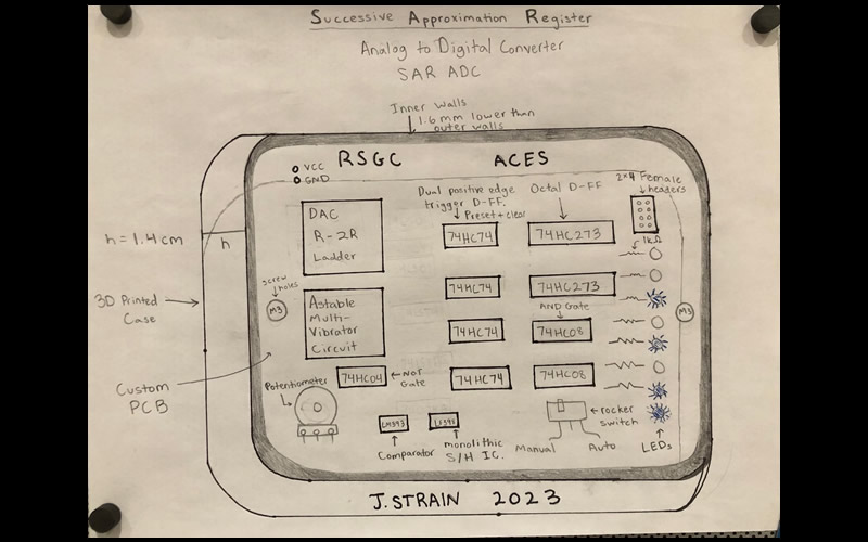
Successive Approximation Register Analog Digital Converter (SAR ADC).
DESCRIPTION The 8(?)–bit Strain Successive Approximation Register Analog Digital Converter will convert an analog input voltage signal into a respective 8-bit binary value. The main ICs for this build include 74HC08 CMOS AND gates, 74HC04 not gates, 74HC273 Octal D-FF, 74LF398 monolithic sample and hold IC, R-2R configuration DAC, an astable multivibrator circuit and the LM393 comparator. This SAR will be connected to a potentiometer to change the input voltage and demonstrate the scaling of LEDs. Additionally for test purposes an LDR or a thermistor will be tested with this circuit. Finally, the outputs of this circuit will be connected to an MCU to demonstrate the conversion results from an LDR or temperature sensor. |
2022/2023 Short ISP Choices
ISPs are gifts. The best choice for you is the one that fits well with your interests, as well as strengths, and blows the doors of your future opportunities wide open!
It takes CONSIDERABLE time and reflection to make the BEST ISP choices but, the good news is that this year you have more options than ever before. For the 2022/2023 ICS4U-E year, the starting point for your Short ISP could come from any of the following areas (no group projects and no duplications),
 As you wind up the final two terms of your secondary education it is time to both advance and lock in your burgeoning engineering skills. Whereas through-hole technology (THT) has had a good run over the past few decades, the future is Surface Mount Technology and Design. For this reason, you best be prepared. This ISP round you will refine your SMD and CAD skills to showcase your Design skills in preparation for the opportunities that await you in the next few years.
Your Medium ISP goal (20% of your final mark) should include the slimmest of useful DES devices consisting of a custom PCB, populated with SMT parts, and encased or hosting (Truth Be Told, Mastermind) 3D printed components in the thinnest form possible (think wallet-size proportions). You have two months. Our 3D Printing TAs, and either JLCPCB or DirtyPCBs are all about to get a serious Sr. ACES workout.
Should you be stuck for a meaningful project, consider a DDPv7 Legacy Shield to complement or replace the ones we already have (Intersection, ADC, Universal v1 or Universal v2). The only stipulation I impose is that these devices must remain compatible with our current EAGLE DDPv7/Shield files.
Download and review the updated Medium ISP Proposal. This Word version I would ask that you edit, attach, and email on Saturday January 14, 2023 under the Subject Line: Medium ISP Proposal.
Long ISP (THT and/or SMT, Fixed or Flex)
 Download and review the updated Long ISP Proposal. This Word version I would ask that you edit, attach, and email to on Monday February 21, 2022 under the Subject Line: Long ISP Proposal.
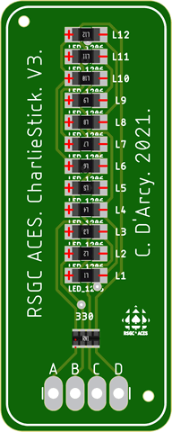
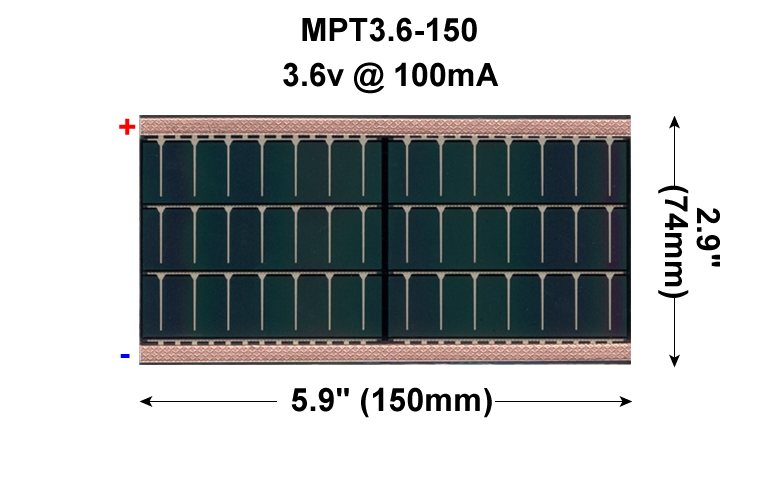
Electronic control over your final ACES ISP must be in the form of custom PCB populated with either through hole and/or surface mount components. In the case of the latter, you can consider taking your design to the next level, in the form of a Flex circuit that will be laminated into a page of your DER. If your circuit proves fully functional a flexible 3.5V, 150 mA Powerfilm solar cell will be included in the lamination so that that viewers of your creativity will marvel at when shown the light of day!
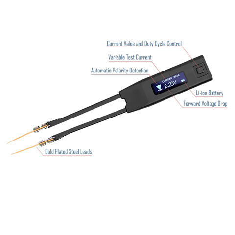
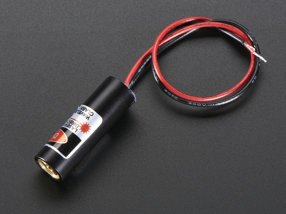
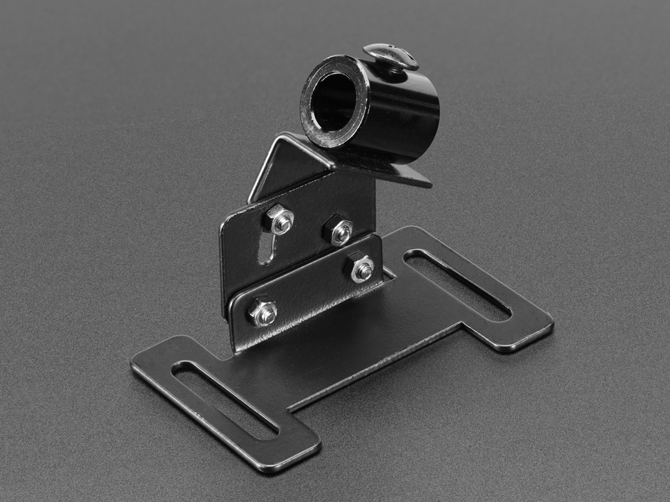
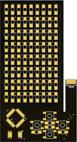
![]() The Flex Circuit concept was first introduced into the ACES curriculum in the 2015/2016 TEI4M year with some impressive results. Where the attempts since have failed is whren the designer becomes too ambitious. If you choose this route, I require that you keep it SIMPLE. (LEDs and resistors only?) Your Medium ISP requirements provided you with valuable experience that should improve your likelihood of success as will be a small project this term that requires the use of the ACES ATtiny85 SMD Trainer. The examples below are too ambitious for us but each offers a unique feature you may wish to consider,
The Flex Circuit concept was first introduced into the ACES curriculum in the 2015/2016 TEI4M year with some impressive results. Where the attempts since have failed is whren the designer becomes too ambitious. If you choose this route, I require that you keep it SIMPLE. (LEDs and resistors only?) Your Medium ISP requirements provided you with valuable experience that should improve your likelihood of success as will be a small project this term that requires the use of the ACES ATtiny85 SMD Trainer. The examples below are too ambitious for us but each offers a unique feature you may wish to consider,
For the bulk of your formal education you have been, and will continue to be, required to consume curriculum chosen for you by someone else. Fortunately (hopefully) you will put this knowledge and skill to good use in your future. However, jumping through someone else's hoops alone does not, typically, secure future success. For that, you must demonstrate your own initiative, motivation, and passion. These qualities need to be cultivated and our Grade 10 hardware course is a perfect place to start. There is so much to learn and there are so many great projects out there that offer stimulating contexts within which to develop and refine your interests.
| Grade | Contribution to Final Mark |
|---|---|
10 |
30% |
11 |
40% |
12 |
60% |


