| 2020-2021 ICS3U-E Engineering Tasks |
Almost without exception one of your first memories is that of a motorized toy you received as a gift and played with endlessly. With luck, you may still have it somewhere, either in your room or a basement toy box. This project gives you the opportunity to revisit some of the mechanical magic you were enthralled with over a decade ago and may consider pursuing in your post-ACES years as a Mechanical/Mechatronics undergraduate.
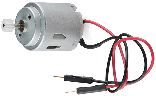
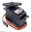
Our ten-class Session 7 instructional focus explored the mechanics of three common motor varieties (DC hobby, servo, and stepper motors). In this project, you are asked to identify one of particular interest to you and develop an interesting prototype that exposes both its (no load) capabilities and your command of the many related concepts you have become familiar with in this course. These include power supply considerations, MCU control, monitoring, measuring, and display options, and finally some simple design aspects (PCBs, acrylic and/or 3D printing mounting and encasement alternatives).
| DC Hobby | Servo | Stepper |
 |
 |
.png) |
The emphasis of this project is on creativity, originality and making the best use of the available resources in front you (components and time) (the only caution I will issue is that if your ISP or previous ACES project involved one of the three motors above, and you a wish to exploit it again, you are expected to take it to entirely new level)
As a starting point for your project considerations, you may wish to review the videos on our course page submitted by last year's ICS3U class that were tasked, specifically, with monitoring the speed of their DC Hobby Motor. Here's a link to their project description. Interestingly, their efforts were undertaken with the first month of the COVID pandemic. Browsing a decade's worth of previous ICS3U course pages will bring you face-to-face with dozens more project videos from Grade 11 ACES that have gone before you.
Finally, one of the reasons I require ACES to document their achievements in text and media (and painstakingly archive their work) is to have them available for inspiration for current ACES to use a springboard for their own accomplishments. Josh Dolgin's Bi-wheeled Rover and Jasper Schaffer's Rubiks' Cube Solver (both undertaken as Grade 12 ISPs) are pinnacles of high-school project achievements you can exploit to open the doors of your admission to University Engineering programs, this time next year.
One of the foundations of a healthy society, in general, and education, specifically, is equity. Since each student's particular situation is unique under this pandemic the equity principle is virtually impossible to adhere to. To this end, I am making this project optional. If it is compatible with the variables you are managing under, complete it. If not, save it for a rainy day.
Our nine-class Session 6 instructional focus is on two wireless communication protocols: Infrared (IR) and Radio Frequency (RF). Should you find either one interesting enough to dig deeper, you are at liberty to pick one of the first two descriptions below and complete a DER project summary based on it. On the other hand, if you UNO and Nano are embedded deep into your ISP pursuit consider one of the two, purely hardware, breadboard alternatives.
Pursuant to our brief look at a possible prototype for a universal remote control in Week 1 of Session 6, you are granted the opportunity to extend the concept by adding additional codes to control either a home device or possibly a motor (hobby, stepper or servo) that are all in your kit and that we will explore in Session 7.
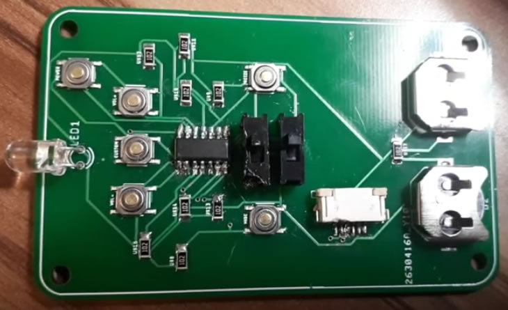
Fola Folarin (ACES '20, Waterloo '25) chose to develop a surface mount version of an IR remote control for his Medium ISP in Grade 12 (pictured, right). Here is Fola's video that accompanied his DER submission: ![]() The DominatIR 2.0
The DominatIR 2.0
 2. Two-Way nRF24L01 Communication
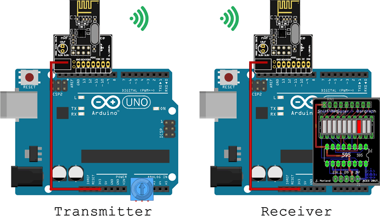
In your possession are a pair of nRF24L01 transceivers. In class you were introduced to one-way communication between two MCUs, supported by the use of these devices to transmit a byte from a base UNO to a receiver UNO.
In this project you have the opportunity to solidify these skills by extending the sample application to support an interesting two-way communication. For example, earlier this year you undertook an exchange between a UNO and a Nano that employed wired serial communication when you complete the ASK,UNO project below. This project offers you the chance to modify that project by employing the pair of nRF24L01 transceivers you have.
Feel free to replace the Nano with a second UNO if that's more convenient and borrow a second breakout board from a peer if necessary.
3. R-2R Digital to Analog Conversion (DAC)
In class your knowledge of resistor networks expanded from the bussed and isolated varieties,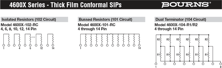
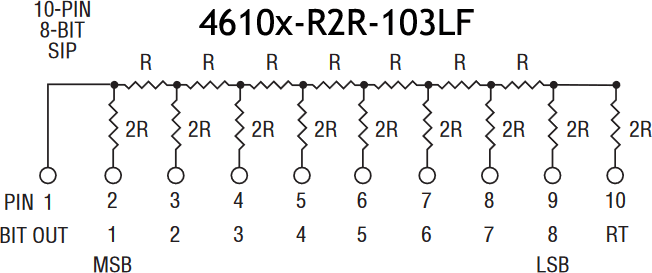 to include the R-2R design (right). You were supplied with such a device in your Session 6 loot bag, the datasheet for which can be found here.
This project asks that you wire up a 8-bit DAC using slide switches and your R-2R ladder to yield an analog output. A DMM or even Analog Voltmeter will be used to confirm the output. It might be a good time to dust of that 12V supply.
 OK, here's a project I've been wanting to do myself for some time. You're invited to beat me to it.
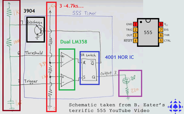
In Grade 10 you were introduced to the 555 Timer/Counter. On watching Ben Eater's remarkable video, you became aware of the internal design of this IC. If you appreciated the significance of this workhorse, this is your chance to recreate it's magic.
Recent instruction introduced you to the LM358 (op)erational (amp)lifier. From the hundreds of op amps on the market, this one includes two comparators, making it ideal for this purpose.
On a breadboard, recreate the 555 by connecting its major components highlighted in the diagram to the right. For the SR latch, your 4001 Quad 2-Input NOR IC from your Grade 10 kit will do nicely.
As I said from the top, this is an important circuit to develop at least once in your life!
![]() ,
, ![]() , and
, and ![]() Project 2.4. Mint Tin ATmega328P (Modified for COVID 19.1).
Project 2.4. Mint Tin ATmega328P (Modified for COVID 19.1).
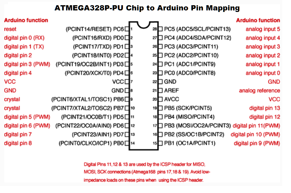
The goal of the embedded system designer is to engineer a real time, in-system programmable (ISP) and functioning ATmega328P-based device, housed in a physical and electronically-stable case. This project gives you your first attempt at creating such a device (and sets your design ideas in motion for our custom PCB and CAD design journey in the second and third terms)
Most (all?) ACES projects combine required elements with creative latitude for students to demonstrate competency in both areas. It is your teacher's belief that your careers will demand this of you. This project is representative of this hybrid pairing.
This project is also designed to be a dry-run for your upcoming ISPs in 2021. As of the date of this initial text (November 15, 2020) you have two months before this project is due, giving you the necessary time to think deeply about what inspires you and to invest this dividend as you see fit. Additionally, your device is to be encased, setting you on the ISP design path in which your device will have custom PCB and housing features by the third term.
Read this 2020/2021 Breadboard ATmega328P Primer
Read this Comprehensive Backgrounder on this Project
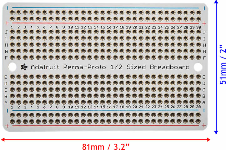
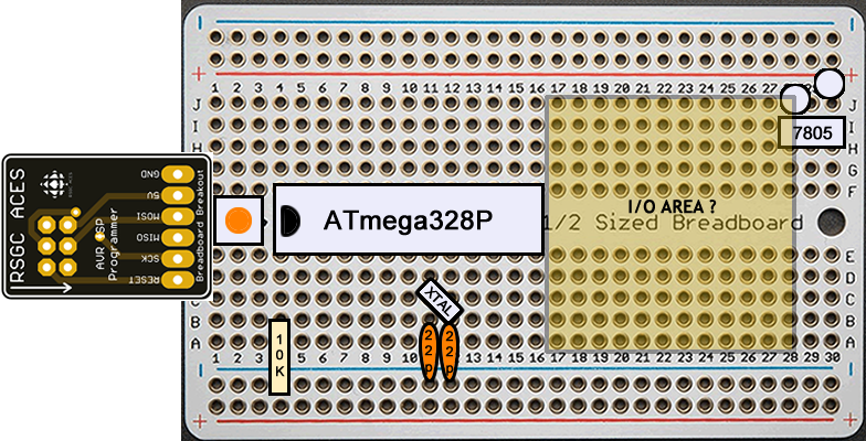 The ULTIMATE GOAL of this project is to create a standalone, sensor-based, In-System Programmable (ISP) (MCU reprogrammable without removing it) device driven by the same MCU at the core of the Arduino, AVR's ATmega328p that will be housed within a closed storage tin with a clear 2"×1.5" viewing window. By way of example, the graphic to the right is a crude simplified layout for a next-to-minimal, standalone ATmega328p on Adafruit's 30-column, Perma-Proto Half-sized Breadboard PCB. I'm sure you'll think of a more optimal layout. Just remember, those 30 columns are precious, so make the best use of them as your design skills will permit.
In the graphic to the right, you'll see the ACES' AVR ISP Programmer breakout board you were supplied with that may be your means to program your in-place SOCKETED MCU (the primer link above provides you with options to consider). On the right, you'll see the 5V regulation section where you may choose to provide a >7V power source as a substitute for 5V power supplied through your ISP BoB by way of your Sparkfun AVR Pocket Programmer.
Most of the additional requirements and wiring are left to you to determine from the direction and knowledge provided in class.
The PRIORITIES of this task are THREE-fold. What your embedded system does is important, but vastly secondary to these three:
If you can accomplish these three things, in a comfortable, confident manner, keep your engineering dreams alive. Now, on to the secondary part ...
Your functioning MCU will sense environmental input of your choosing (light, temperature, time, audio, etc) and display the result on an optical device of your choice (LEDs, 7-segment displays, bargraph, matrix, etc) (that can be viewed through the clear window, with the lid fully closed should you elect the optional stages of this project.
Task 2.4.1. Breadboard ATmega328P.
| Supplemental Parts List for 2.4.1 | |
|---|---|
| # | Description |
| 1 | RSGC ACES ISP Breakout v2 |
| ? | ? |
| ? | ? |
| ? | ? |
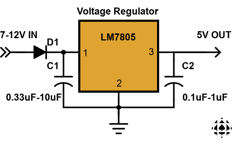 Power MUST come from a 9V power source. This will require you to create onboard 5V regulation using your LM7805 and shoulder caps, to smooth spikes.
Task 2.4.2. Perma-Proto ATmega328P (Optional: See Conditions in Conference email on December 1).
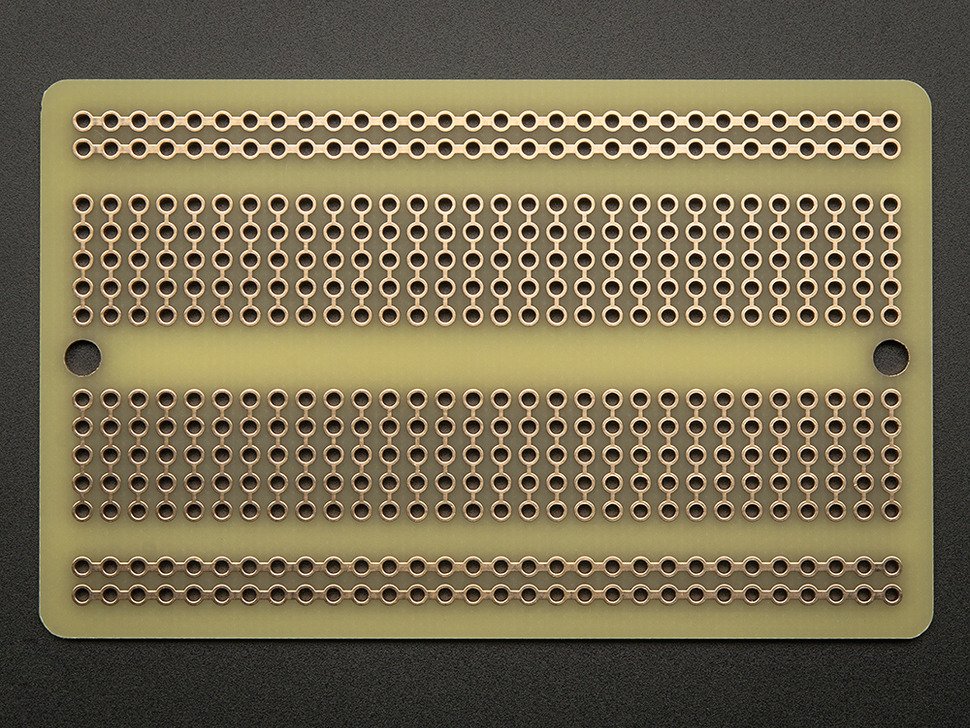
| Adafruit's Perma-Proto Half-sized Breadboard (30 Columns) | |
|---|---|
| FRONT | BACK |
 |
 |
| Supplemental Parts List for 2.4.2 | |
|---|---|
| # | Description |
| 1 | Adafruit Perma-proto 1/2 Sized PCB |
| 1 | PJ-005A 2.1mm power jack |
| 1 | 1x6 Female ISP Socket (straight or RA) |
| 1 | Rectangular Metal Tin with Window |
| 1 | 10X Aven Loupe, Magnifier |
| ? | M3 5 mm Nylon Screws |
| ? | M3 Nylon Nuts |
| ? | Screw Terminal Blocks |
| ? | 5mm LED Holder |
| * | Heat Shrink Tubing |
| ? | ? |
Task 2.4.3. Mint Tin ATmega328P. (Optional: See Conditions in Conference email on December 1)

![]() Project 2.3. Ask UNO.
Project 2.3. Ask UNO. ![]() for 2020/2021. This project is specifically tailored for the 7-Class, Session 3 segment of COVID-19.1 (my notation for the Year 1 of likely many under COVID-19). I hope you have as much fun developing it as I had imagining and crafting it. The goal is to achieve the final prototype in as stress-free a fashion as possible, by undertaking a sequence of introductory conditioning stages.
for 2020/2021. This project is specifically tailored for the 7-Class, Session 3 segment of COVID-19.1 (my notation for the Year 1 of likely many under COVID-19). I hope you have as much fun developing it as I had imagining and crafting it. The goal is to achieve the final prototype in as stress-free a fashion as possible, by undertaking a sequence of introductory conditioning stages.
Smart Personal Assistant Systems (Siri, Alexa, Home, Nest, etc.) are all the rage and, while we're not at the wireless hardware and AI software stage yet in this course, we can begin to imagine how a simple 'intelligent' wired system might be put together.
Stage 1. Watch this ![]() short video with the goal of recreating your own prototype of the same, as follows,
short video with the goal of recreating your own prototype of the same, as follows,
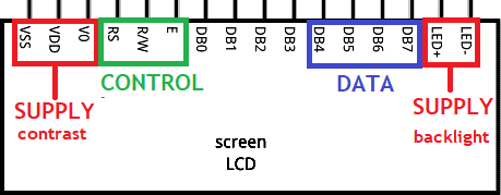 Wire your Nano (not your UNO; that comes later) and your 16×2 Character LCD Screen together on a breadboard, as reviewed in class.
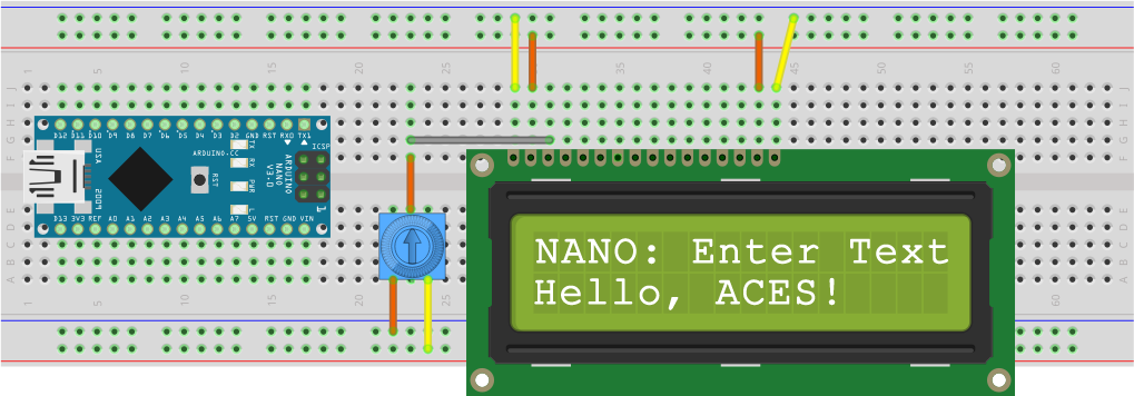
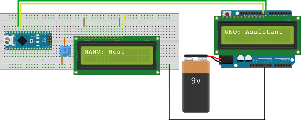
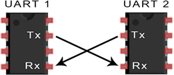
Stage 2. In this stage, we wish to establish communication between our Nano Host and our UNO Assistant, while maintaining the ability to access the Nano through the Serial Monitor. Since there is only one Hardware UART system on the both devices (each based on the ATmega328p) we need to employ the Arduno's SoftwareSerial Library to emulate the Hardware Serial UART on any two pins, so the Nano and UNO can talk to one another (again, while leaving the Nano's Serial Monitor available for your control).
Before we address the software serial communication connections, consideration must be given to powering both MCUs. A review of this blog suggests that since the Nano Host is our primary device (drawing power from our laptop's USB Cable) when the system is up-and-running, power for the UNO Assistant could come from a second 5V USB source (or, better yet, your 9V AC/DC adapter you should still have from Grade 10) into the barrel jack connector of the UNO.
One more power consideration is access to a common ground. Two independently functioning electric systems will only function in a coordinated manner if they share a common ground reference. This is easily achieved by connecting the grounds on both MCUs together, with a wire. Assemble your hardware prototype as shown, replacing the 9V battery with your 9V ACDC wall adapter, if possible.
 The first software task is to create code that will reside on the UNO Assistant that simply echoes the text passed to it by the Nano Host. Create an Arduino Project by the name of UNOLCDFromNANOHost and drop in
 Project 2.3. Ask UNO
Basic Task
Your Nano Host requires the suppport of your UNO Assistant for the evaluation of 'simple' arithmetic expressions. By 'simple' I mean your UNO Assistant only accepts expressions in the form, a?b in which the operands a and b are limited to single digit ASCII characters and the ? is one of the 5 arithmetic operators. +, - *. /, or %.
| Nano Host Passes Expression... | ....UNO Assistant Result Returned |
|---|---|
| 6+5 | 11 |
| 9/4 | 2 |
| 7%3 | 1 |
| 4-8 | -4 |
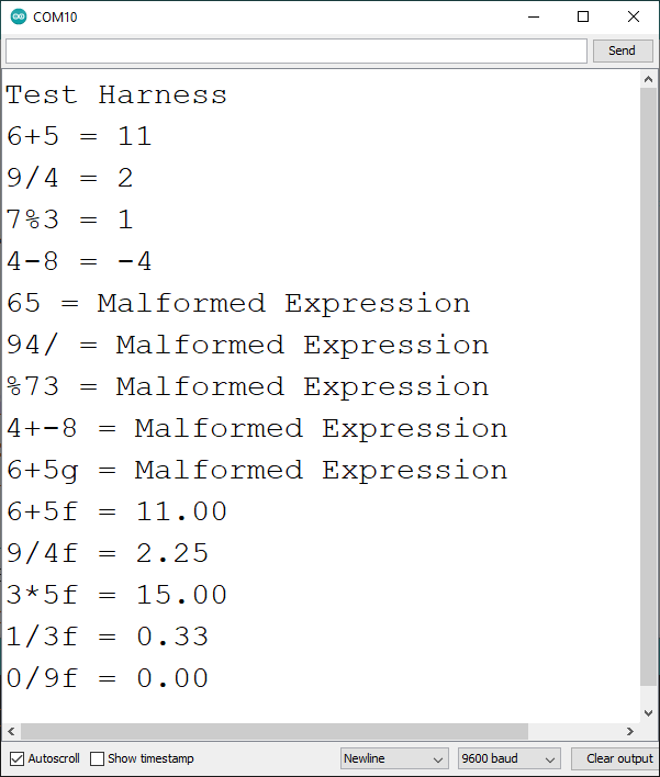
Expressions of the correct form a?b are entered by you in the Serial Monitor and read by your Nano Host. The Nano Host echoes the original expression on the second row of its LCD and transmits it, in its original form, to the UNO Assistant which also echoes it on the second row of its LCD Appliance. The UNO Assistant will parse the String expression, evaluate it, display the result on the second row of its LCD Appliance before transmitting its String equivalent back to the Nano Host for display on the second row of its LCD screen. The original expression and its evaluated result are presented for 5 seconds on both screens before the Nano Host requests the next expression from you through the Serial Monitor.
For the Basic Task your code can assume the user enters correctly-formed expressions. The operands and result remain as integers. You can assume the user does not request division by 0.
Here is a ![]() video of what you're going after, including a samples of Enhanced Tasks that include handling malformed expressions and floating point evaluations.
video of what you're going after, including a samples of Enhanced Tasks that include handling malformed expressions and floating point evaluations.
Enhanced Tasks
The door is open for creative extensions by inspired ACES, but know yourself and your own personal risk tolerance. Here are some possibilities that you might consider.
| Nano Host Passes Expression... | ....UNO Assistant Result Returned |
|---|---|
| 6+5f | 11.00 |
| 9/4F | 2.25 |
| 3*5f | 15.00 |
| 1/3F | 0.33 |
| 0/9f | 0.00 |
Final Words
 Please do this on your own, seeking a sensible amount of Forum assistance, if necessary.
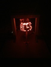
![]() Project 2.2. Persistence of Vision. (Reference: AVR Foundations: pp.35-38). It's strange to think that our eyes perceive much of the LED lighting around us to be uniformly ON, when they are actually OFF as much as half the time (maybe this is one of the reasons LED lighting is so cost-effective?). The next time you're in the DES, point your phone's camera at the digital clock and observe the interference bands generated by clock's display alternation and your camera's periodic scan rate.
Project 2.2. Persistence of Vision. (Reference: AVR Foundations: pp.35-38). It's strange to think that our eyes perceive much of the LED lighting around us to be uniformly ON, when they are actually OFF as much as half the time (maybe this is one of the reasons LED lighting is so cost-effective?). The next time you're in the DES, point your phone's camera at the digital clock and observe the interference bands generated by clock's display alternation and your camera's periodic scan rate.
 |
 |
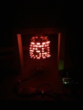
Perhaps the most remarkable ACES PoV creation was engineered by K. Fiset-Algarvio (ACES '19, Guelph Mech. '23) in his amazing Grade 11 ISP:![]() The Persistence of Vision Globe. Above are two images extracted from his DER. Be sure to watch his detailed video.
The Persistence of Vision Globe. Above are two images extracted from his DER. Be sure to watch his detailed video.
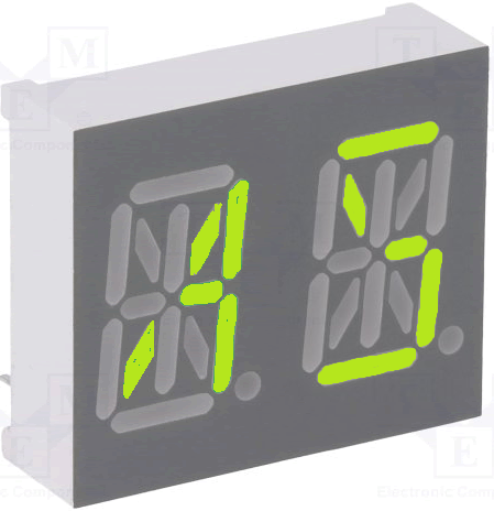
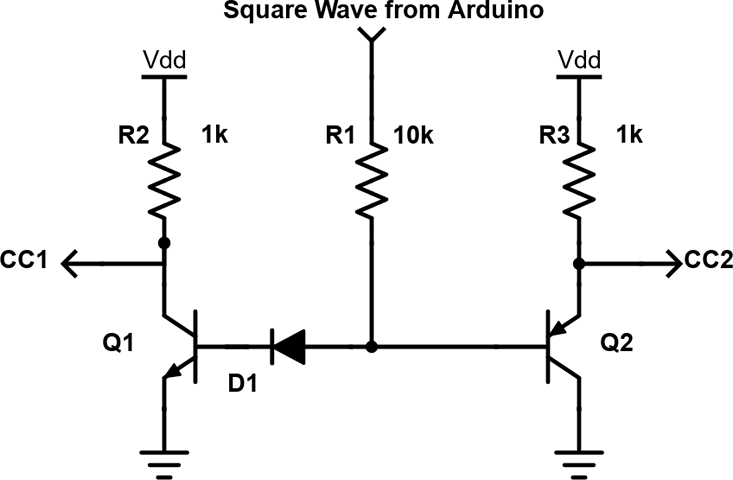
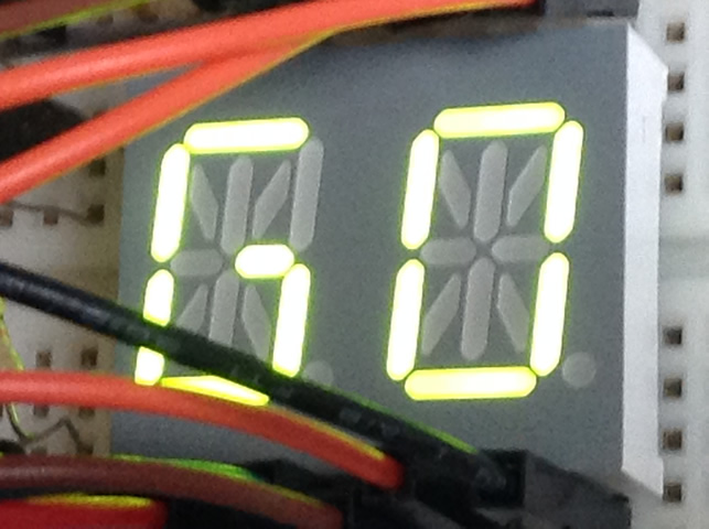
You have two 14-Segment Dual CC Alphanumeric Displays in your kit. An image of the device appears below, left, in which I have coloured a few segments to simulate a 'possible' depiction of the two-letter word AS. Here's the link to its datasheet so you can familiarize yourself with its pin layout. Given its 14 segments, this component can be driven by two SN74HC595 shift registers* and a pair of transistors (one NPN and one PNP) under control of a SINGLE square wave (bottom, right), in a Persistence of Vision scheme.
*Although the ATmega328p has enough pins to complete this task without using shift registers, you are required to do so, for practice.
 |
 |
 |
BASIC Task. (Adapted for 2020-2021)
For the ambitious, consider the following any or all of the following. If you implement any enhancement add a section on you DER entitled Enhancement and document your creative extension(s).
ENHANCED Task.
Advice (trust Mr. D's experience)
 This is a CHALLENGING project. Do NOT doubt yourself, you are all talented enough to complete it. Success follows those who simply devise a SMART plan and have the DISCIPLINE to execute it.
For many of you, next to your Secondary School Graduation Diploma, your DER will be your most important high school document as the two of them may very well open the doors to your careers.
Take great pride in your craftsmanship of this work.
![]() First, make the following edits to your DER,
First, make the following edits to your DER,
Project 2.1. Traffic Light. Since many of you will be pursuing your driver's license in the near future, the focus of this first project is the careful soldering and QUALITY programming of a standard traffic light. When Jasper Schaffer (Fraser's older brother) (ACES '18, Queen's '22) was in his ICS3U year, he designed the handy little PCB pictured to the right that we'll exploit to start our year off. For the assembly aspect of this project you will solder one each of a green, yellow, and red 10mm LED and a four-pin right-angle header from your toolkit onto the Schaffer Traffic Light PCB you have been provided with. Take care as there are NO replacement parts. The right-angled male header pins allow your device to be inserted directly into adjacent female port pins on your Arduino (eliminating the need to use a breadboard and hookup wires). Be sure to document your soldering of the device through video acquisition that you can include in your report. For the testing aspect, you will include media as well as a well-planned sketch modified but based on our discussions and models in class. The fully documented sketch should cycle through the LEDs continuously with the green and red remaining on for four times the duration of the yellow (amber) LED.
In your Report, you are include the Purpose, Reference, Procedure, Code, Media, and Reflection subsections in Heading 2 style. A full Parts Table, with background shading consistent with your previous ICS2O colour theme and width of 3" and should appear right-aligned within the Procedure section. Finally, ensure that no content is allowed to spill into any of the four page margins.
 Infrared Remote Control
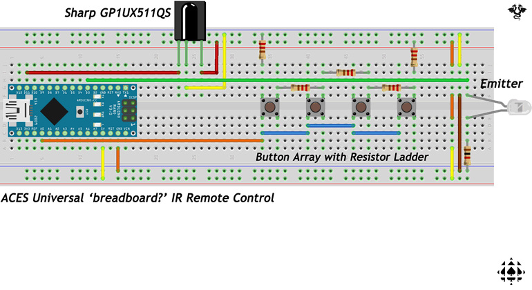