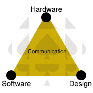
 The Mint Tin ATmega328P project is yet another 'evolutionary' ACES journey in which current ICS3U students build on the achievements of their predecessors to establish and solidify their own hardware, software, and design skill sets. Typical results are tight, well-engineered pocket-sized embedded systems bursting with gems of creativity and great ideas that set the stage for the next iteration, a year from now. Feel free to return to previous ICS3U course pages and watch their Mint Tin ATmega328P videos to inspire your own embedded ambitions.
Concept
As you near the end of your first ACES Arduino term, it is the right time to gain valuable perspective, understanding, and appreciation for this ingenious device. You will tear down the Arduino, conceptually, and build a similarly functioning prototype, based on the ATmega328P MCU, on your solderless bread board (SBB) with many of the parts that are in your kit.
Once that is accomplished, and applicable media recorded for your DER, it will be time to consider a more permanent version of your standalone Arduino. This will require the transfer of components from your SBB to a soldered circuit boards of which there are a number of options. Custom PCBs are not the answer at this stage as they offer little more than a point-by-numbers exercise with little opportunity for the unique creativity of each ACE. Generic solderable prototyping boards, in particular, Adafruit's half-sized perma-proto boards, offer the best compromise of ease of transfer from your solderless breadboard and creativity.
An introduction to custom 2D/3D PCBs/Cases comes later in this course. The added benefit of these 1/2-size perma-proto boards is that their form lends themselves well to convenient and adaptable, off-the-shelf, containers. By undertaking the constrained tasks of imagining and adapting a common case for individual needs you can gradually begin to appreciate the challenges and considerations that must be brought to future design efforts.
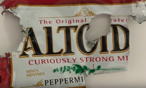
Small rectangular tins, such as those that house Altoids mints, have proven to be a versatile housing for DIYers across the web for their MCU projects. While their size is highly appropriate, adapting these tins for external power, in system programming, and sensing is tricky and often requires additional workshop tools.

Constraints
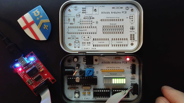
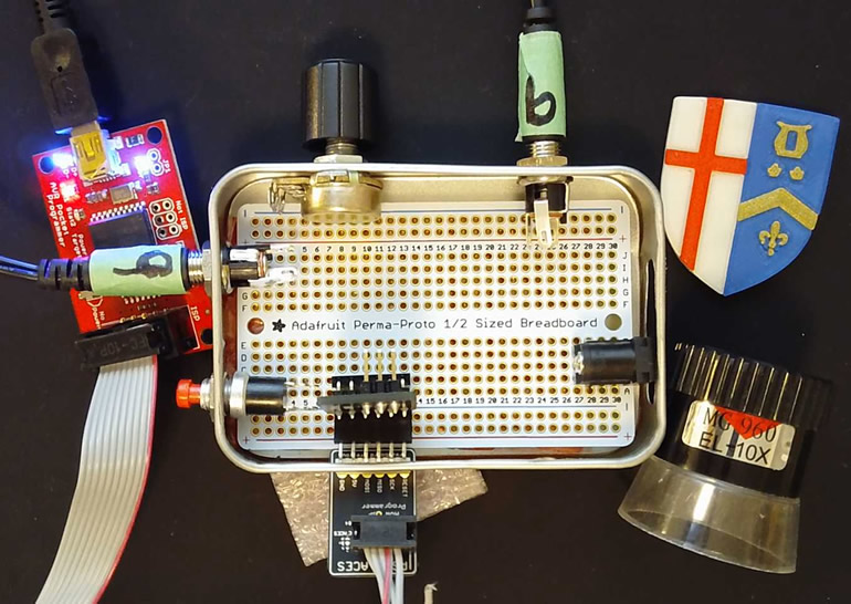
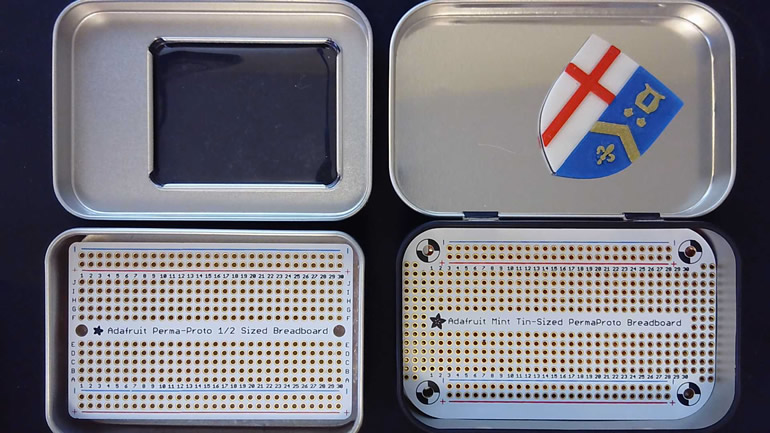
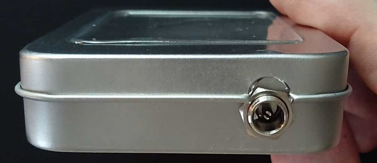
You are to put yourself literally and figuratively, in a box. While this project affords you substantial latitude and creativity over what your ATmega328P-based circuit does, you have only limited options for the circuit board and metal tin you are required to use and adapt for your users' experience. The options appear below from which you will select one. These components have been scrutinized for use over the past two years and selected for the relative ease of manipulation and the consistency it affords ACES as a common project foundation. You have the perma-proto PCB below left. Should you prefer to use the mint tin variation on the right, just let me know and you will be provided with one. As for the tins, the one below left has a brushed silver finish, a convenient viewing window, it is slightly smaller, and the top is not hinged. The tin on the right has a black finish, is slightly larger, no viewing window, and a hinged lid.
Finally, as much as many of you would make good use of the wide-open freedom to develop any embedded system you can dream of, there are equally good reasons to impose on the constraints of these PCBs and tins. The most important reason upholds one of the greatest strengths of our program which is the mutual support ACES offer each other. Whether it be in-class advice to a peer, contributions to our transparent email conferences, or your Discord back channels exchanges, if everyone is working with the same first-time materials, all students benefit from each others travails.
The second reason is that future employers will impose similar constraints on the team projects ahead in your life. You will always be expected to strike a balance adding creativity where your imagination will allow while sticking to the baseline projects' requirements imposed externally.
Perma-Proto Boards
 The options for transferring temporary solderless breadboard prototypes to more permanent soldered platforms are virtually limitless. Adafruit offers a line of generic PCBs, called perma-proto boards, that make it easy for first time DIYers by providing durable solderable circuit boards that mimic the appearance and layout of standard solderless breadboards (SBBs). In addition to the two featured above, you'll find both 1/4-size and full-size versions, available singularly, or in multi-packs. These are widely available from Amazon, Digikey, Creatron, ABRA and many other retailers. In addition to the traditional layouts, Adafruit offers all sorts of non-standard perma-proto layouts you may wish to research.
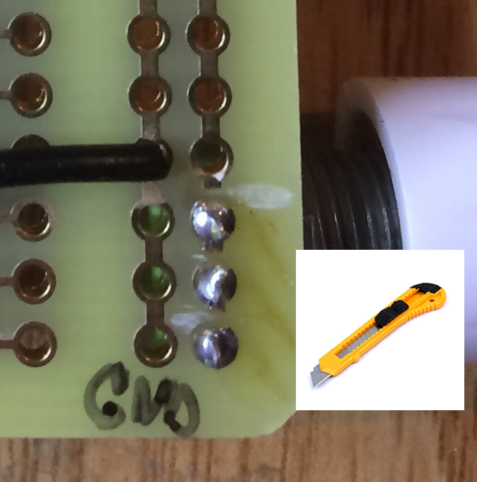
To maximize the versatility of your perma-proto based device, unlike SBBs, you can access the traces on the back. By careful and strategic cutting of the copper traces, you can isolate components electrically from one another in areas that would normally be continuous on a standard SBB. Click on the image to the right to see a clear view of what one maker did to isolate a small section.
Adafruit offers a convenient tutorial on Perma-Protos that I highly recommend reviewing as early on in this project cycle.
Sockets and Headers
 Sockets and headers provide a number of advantages for the prototype developer. The primary benefit is avoiding the potential damage due to excessive heat applied directly to semiconductor components. Additionally, the freedom to remove components, either for swapping for debugging purposes or temporarily removing parts for use in other projects, lowers expenses.
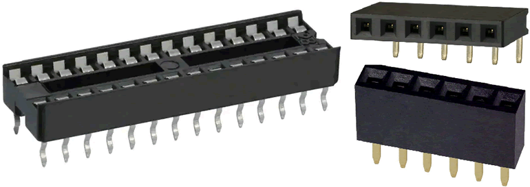
IC Sockets, together with male and female headers, typically come in either tin or gold plating, with the latter being more resistant to oxidation. When ordering, ensure the correct pitch (distance between pins) of 0.1" (2.54 mm) for breadboard and perma-proto applications.
Another option for IC sockets is the 'kinked' pin variety. ACES soldering applications require their PCBs to be turned upside down. Kinked pins ensure the IC socket remains firmly in place.
The image samples to the right include the 28-pin kinked IC socket for the ATmega328p, and both the straight and right-angle varieties of the 1×6 female ISP headers.
Punches
 The advantages of working with tin include its strength and appearance to name two. A weakness for DIYers is its inflexibility to cutting and shaping, without the right tools. Sloppy cutting can lead to sharp edges and susceptibility to cuts. Power drills and Dremels are good solutions in the hands of experienced users but, even with firming backing material, drill bits are typically too aggressive and can easily ruin a case.
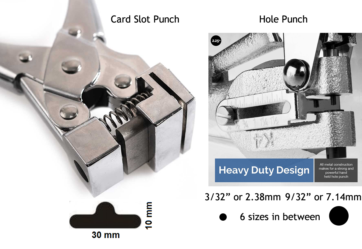
A good solution I have found is to use heavy-duty handheld punches like the ones below. The one pictured below left does a satisfactory job of punching out wide slots typically used for create slots in plastic cards for name tags. Although it is tricky to remove after punching. The one below right is terrific for punching circular holes ranging from from 3/32" to 9/32" in diameter.
 Drawbacks to both of these devices include the depth of the jaw and the distance from the edge as you'll come to realize. The cases I plan to provide you with have total depth of 0.8" This is not quite deep enough to create an opening in the wall of the base and have the lid close without some form of relief in the lid. I have this slightly deeper mint tin on order for mid-December. At a depth of 1.4" it will likely be a better solution. I have these and am willing to coordinate your access to them if they provide the advantage I anticipate.
Panel Mount
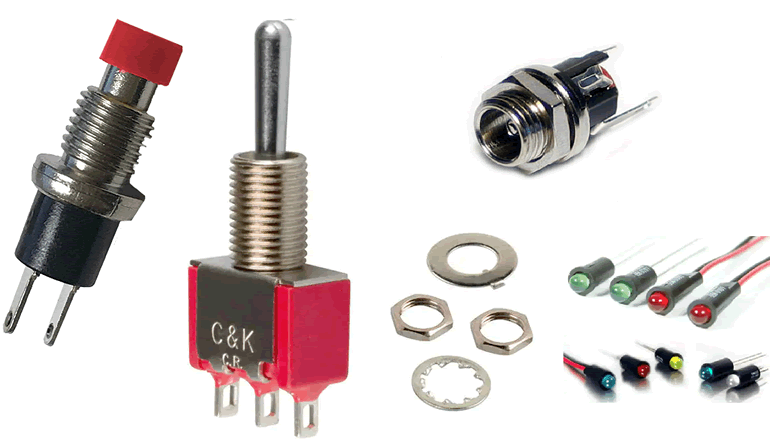
You may remember the red- and black-topped push buttons from your Grade 10 kits. These were not breadboard-friendly as they are intended to be mounted on a panel (thin metal/plastic) just like our mint tins. Should you decide to order additional components like the actuators and indicators below, please be SURE! to confirm the diameter of the threaded ground sleeve matches our/your ability to create a clean mounting hole in the wall of your tin. For example, one of the parts I will supply you with is the PJ-005A 2.1mm power jack to fit the barrel of you 9V barrel plug. The 9/32" hole from the punch, above right, is just large enough to take the sleeve. Remember the washer stays on the inside and the number secures the components from the outside.
Known Challenges
 Keep this really simple. Do NOT be too ambitious with this first project attempt. Do not set out to impress with overzealous enthusiasm. Temper your imagination and keep to a familiar application, elegant, and stress-free while enjoying the high expectations for handling these new materials. Save that crazy Kickstarter device you've had in your head for V2, or even V12. Unfortunately, I will not be sympathetic when it comes to marks if you are not realistic.
- Think, before designing and building at EVERY Stage. The obstacles, pitfalls, and dangers can never be fully anticipated heading down a road for the first time but your collective experience can still guide you to some extent.
- Shorting. As the case is metal, it CONDUCTS. Consideration and care must be taken in the design and assembly with respect to to insulation, padding, and clearances. Thin bubble-wrap, foam and electrical can be used to line inside bottom, walls, and top. Small, M3 nylon screws and nuts I can supply you, inserted into the holes of the PCB, can elevate it slightly off the bottom.
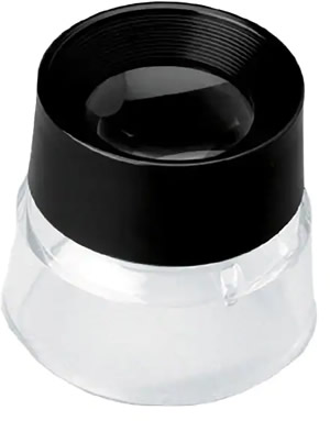
- Solder with a DMM and a Magnifying Glass. The soldering is REALLY TRICKY, primarily because, even the most steady hands can inadvertently, cause the solder to bridge holes and result in, hard to detect, shorts. For this reason you must have a DMM (I will lend you, if necessary) to test for continuity issues IMMEDIATELY after soldering each component and a small 10 X magnifying glass I will simply give you, to keep.
- Sequencing. The final assembly of your devices, in particular the sequence, may be tricky. Clearly, in the image of the sample installation above, the soldered PCB must go in fairly early in the assembly stage as the panel-mounted components may block such.
Task
Return to your ICS3U Task home page for this specific year's expectation.
Future
Your experience with this project, combined with the design skills yet to come in this course may motivate you to convert your imagination into something along the line of the prototype below. After a generally successful inaugural version of this project, I designed version 1 of a custom PCB that worked to a large extent. Two voltage dividers (one based on an LDR and the other a potentiometer) were read and mapped to a bargraph-based VU meter. Click to enlarge.
 Watch this 3:00 minute video demonstration of this PCB in action.