Clock.You're 2 for 2 this year; let's go for the sweep. With your engineering, communication, and collaborative skills well-established, it's time to focus on, arguably, the most challenging skills of all:
R & D (Research and Design)
You are acutely aware of the premium our world places on passion, creativity, innovation, and imagination. Your future success will, assuredly, depend on how deeply you have cultivated these assets.
The final project of this year's course requires you to design and engineer a clock within the framework of required and discretionary specifications. The required skills listed below are designed to ensure to ensure that each student is prepared for the final exam in two month's time.
Required Specifications
Individual Project (each student is responsible for both the hardware and software requirements of their clock)
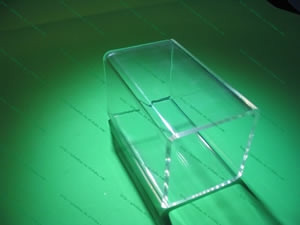
The housing for the unit will be a length of square, acrylic tube.
No two student clocks will be identical with respect to the electronics
The pulse for this project comes from an IC referred to as a Real Time Clock (RTC). One of the more common devices is the DS1307. A description from the Datasheet for this two-wire, 8-pin DIP is as follows...
Arduino RTCLib Software Library
You have a number of options for software interfacing with the DS1307. You can develop the code from scratch or use an existing library. AdaFruit's tutorial for the DS1307 Breakout board recommends the RTCLib library from JeeLabs that can be obtained from GitHub. Here's a quick look at the RTCLib header file (RTCLib.h) in which you can see the functions it makes available for your sketches.
~~~~~~~~~~~~~~~~~~~~~~~~~~~~~~~~~~~~~~~~~~
Design Proposal (April 13)
Based on our discussions combined with your own research and over the three classes this week, you are to prepare and submit your proposal for your Tube Clock. Your ER proposal will include,
Overarching rationale for your design philosophy and decisions
Links to online clock projects that inspired your design decisions
a comprehensive description of the unit that addresses all of the required and discretionary specifications above, indicating those details you are confident about and those that may require further investigation (don't leave too many of the latter)
a Part List so I can start accumulating your parts
Prototype (April 30) The ATmega328 will provide the logic side of your circuit. It is not designed to supply the power to your display components. So, your most important consideration for a successful implementation of your design will revolve around the ICs you select to provide optimal current and voltage requirements to your display devices. This is not a trivial design decision. Particular ICs can provide HIGH side (source) and LOW side (sink) current, latch, and decoding (BCD to 7-segment) functions, offering many options for the designer.
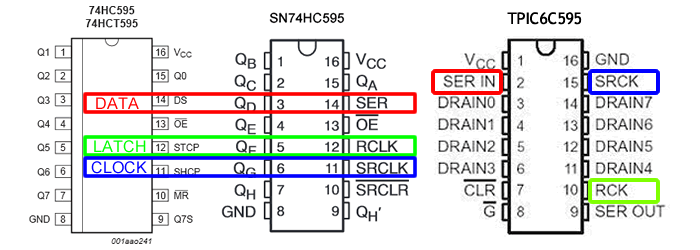
SHIFT REGISTERS: Although the pin outs are identical, depending on the 74HC595 datasheet you use from any given manufacturer, the labels on the pins may be different. Here are two examples, the one on the left is from NXP and the one on the right is from Texas Instruments.
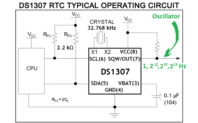
LCD CONSIDERATION: With the SQWE bit enabled, the DS1307 Square Wave output is activated as 'open drain' meaning it can sink but not source. For this reason a pull up resistor (10kΩ) is required as shown from the capture below taken from its datasheet.
Taking into account the particular current requirements of your clock design, select the correct shift register, sink or source, decoder combination of ICs (74HC595, MAX7219CNG, HEF4794B, HEF4543B, UDN2981, etc). On an expanded breadboard, prepare and demonstrate the full prototype. This includes the switches/button assemblies. ER details will include,
shift register and sink or source details and design and implementation discussion
switches/button discussion
HEF4794B Application example: serial-to-parallel data converting LED drivers (Datasheet p. 12)
PCB Fabrication (Strict: Sunday May 18)
Although you've done this a couple of times this year (Intersection & Console), there are a few new considerations for this project.
Be sure to acquire media throughout this stage for your ER.
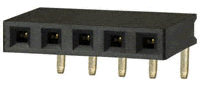
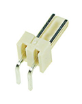
One option for mounting your RTC Breakout board for easy access in a multi-board configuration is to use a 5-pin right angle female header such as the one pictured to the right.
In attempting to limit the sizes of your boards, you may have to monitor the width of your gaps. If they are too narrow, etching may not be able to remove the copper as can be seen by the adjacent, unsuccessful attempt. An hour and a half did little to remove the copper in the gap and, inadventently started overetching other areas.
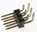
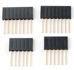
Long breakaway male headers combined with female headers offers a convenient method for transferring signals between layers in a two-board configuration. For multi-board arrangements, stackable headers are needed. If necessary the boards can be easily separated for maintenance. Placing the pins symmetrically at the ends of the boards can increase overall stability of your structure. Inventory in both 1x6-pin and 1x8-pin arrangements is available. In EAGLE, search for FE06-1 and FE08-1, respectively for the footprints.
ViaCAD (Tuesday May 20)
Your design may require one or more openings in the acrylic tube for access and viewing features. Mr. Elia will attend this one period to provide support for the creation of your CAD file. From there, your tube will be laser cut to your specification.
Demonstration (Tuesday May 27)
You are to provide a thorough demonstration of your clock to Mr. D. no later that the afternoon of Tuesday May 27.
Final (Tuesday May 27)
Final ER submission. Demsntrate your technical writing ability and formatting skills!
ACES Game Console. Our focus for Term 2 is the design, development, and production of the LED-based, hand-held, ACES Game Console.
Final (Tuesday March 4 through Friday March 29). After debugging any issues, mount your PCB, assemble, install your cover plate, and test your Console. Document the complete process and add subsections to your ER Console writeup. Be thorough.
Cover Plate (Monday March 3). Your PCB is populated, it works, and you have your Console at the START of class. By the END of the class you are to submit the file nnnnCoverPlate.vc3 to handin (where nnnn is your surname). This plate will be laser cut and returned to you at the START of class on Wednesday March 5. Of primary concern is the placement of the four rectangular openings for the buttons. Since the text worked out so well on the Intersection plates, you will want to consider this carefully. In addition to, possibly, your name and a title, you may want to have 8421 engraved under each rectangle from left to right to support Stevie's binary game which is currently working and available for upload to your unit.
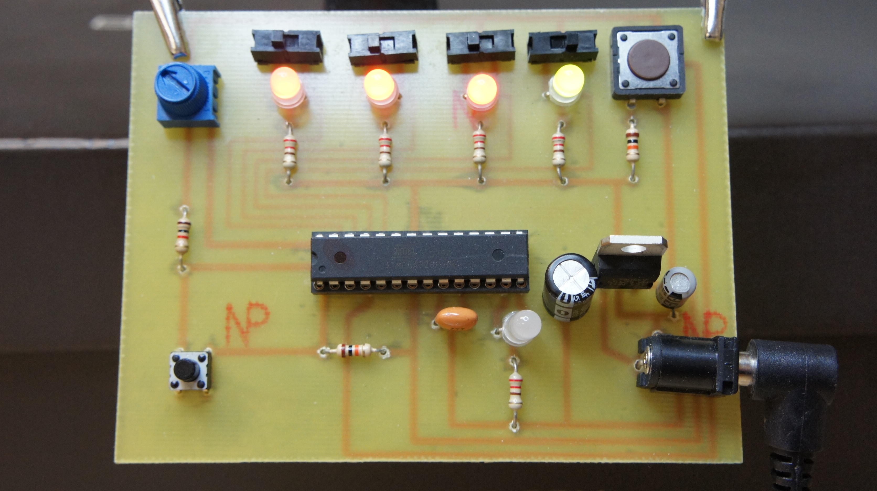
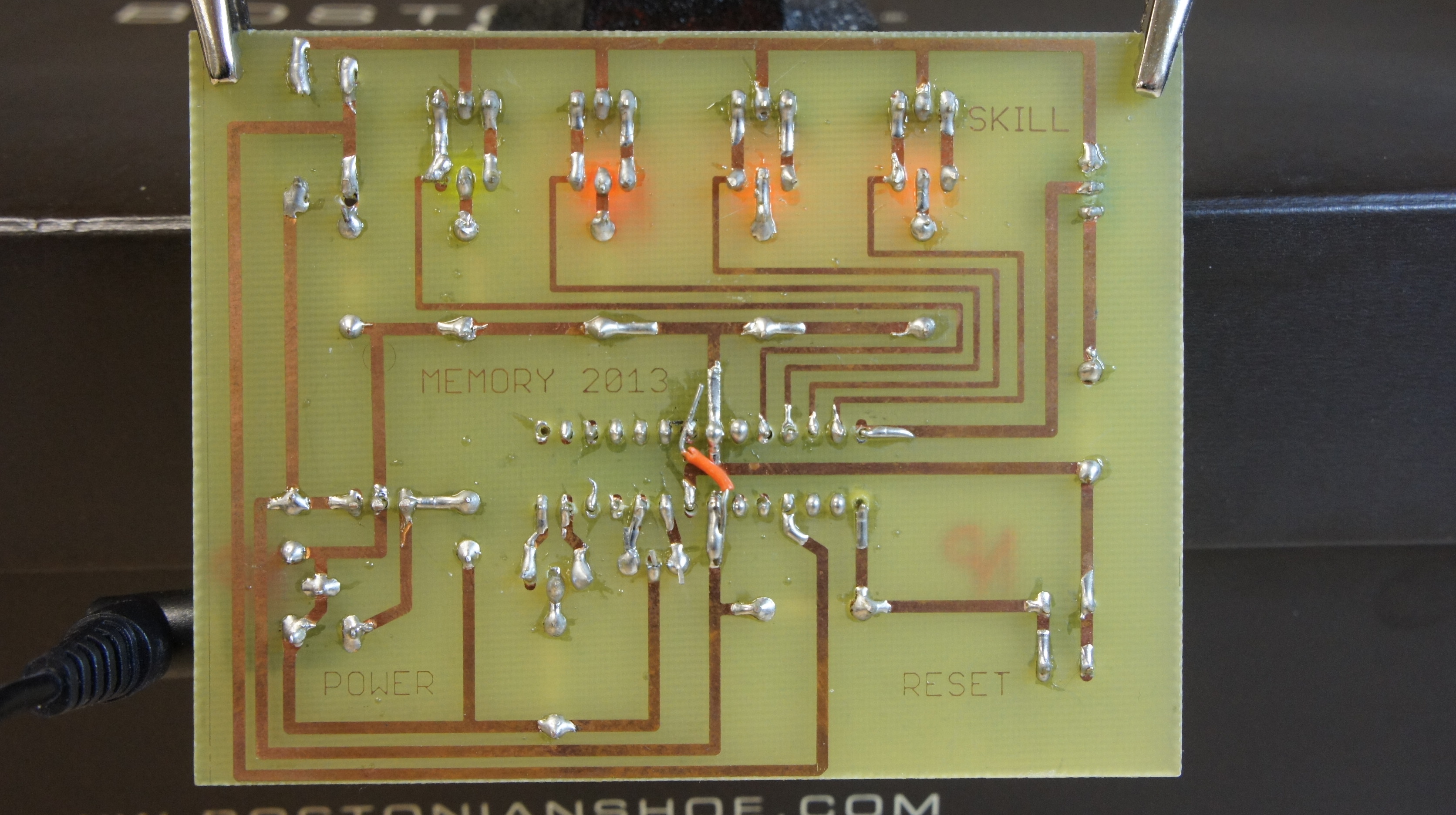
PCB Fabrication (Wednesday Feb 19 though Friday Feb 28). We have all invested a great deal of time, effort, skill, and money to get to this point, so there is a lot at stake beyond just a mark. This is more about the present and lasting pride of accomplishment. You get one shot at this. If you think deeply, bring all your previous engineering experience forward, double- and triple-check your work, with your partner, and others, you will enjoy a successful outcome. As an incentive for being the best you can be, only fully-functioning boards will be awarded a console case.
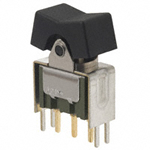
Once your off-board prototype is confirmed as working, take a photo and a video. Dissassemble the circuit returning 4 SPDT switches and 2 momentary PBs to me in exchange for your new final parts kit. The parts details you require can be found below. Retrieval of the required EAGLE parts within the ADD menu is made easier if you follow my BOM located here. Working with these specifications below, design, etch, and drill your Game Console PCB. A number of required components are indicated below. Document the process and add subsections to your ER Console writeup. Be thorough.
Board Tips
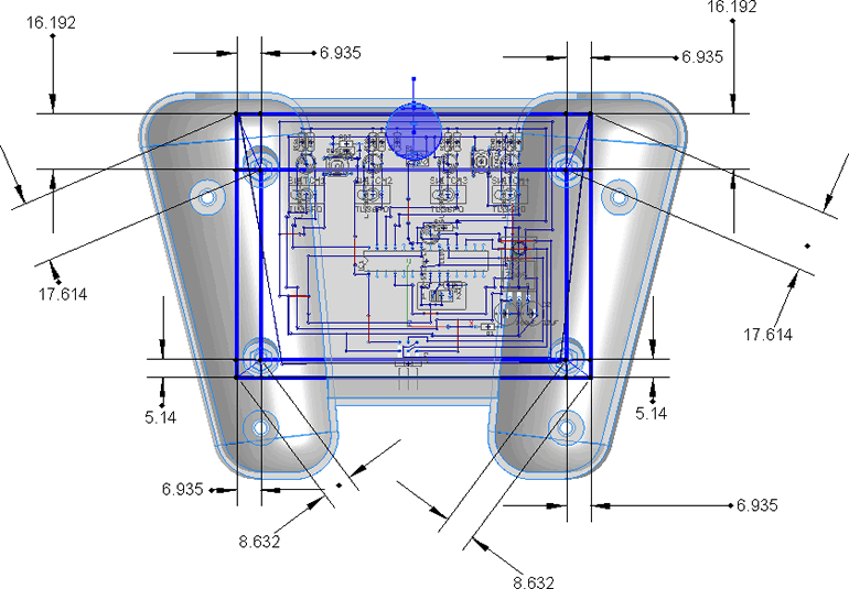
Be sure your outer board dimensions are EXACTLY 4" by 3" BEFORE placing any parts and keep an eye on it.
Place the mounting holes on first. They are located at: TBA
Recess the 2-pin molex connectors along the sides so they do not extend beyond the board.
Position the 2x3 ISP header at the bottom, middle and recess so that the ends and edge line up. Do not extend over the edge of the board.
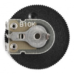
The 10K Thumbwheel Potentiometer (SKILL) must extend EXACTLY 3.5 mm beyond the top middle of the board. This allows for the thickness of the case (2mm) and 1.5mm exposure.
All parts MUST lie as FLAT as possible. Position the L7805 so that it can lie FLAT.
Four sessions are allocated for each group to develop a working prototype of their Memory Game. Each team will start by confirming the contents of their Parts Kit against the List to the right.
Partners will combine their hardware and software skills to get the prototype functioning.
In parallel with prototype development, partners will also use their EAGLE skills to develop the Memory Game Schematic. Do not extend the schematic to a board view as this will require further class discussions that depend on case considerations.
Board View
Be sure to add the new parts (switches and 2x3 ISP Connection) to your schematic. See recent posts to the TEI3MForum to make sure you've got it all. See Ross' post to the TEI3MForum for the 6-pin ISP Connector and ensure ALL six pins are wired in, ensuring the 5V connection taps into the OUT pin of the 7805 regulator.
With the schematic finished and the parts identified, hardware partners can focus on the Board view of the Console.
Pass along the EAGLE .sch and .brd files to your software partner so each of you can update and submit your ER for this Sunday's deadline.
Requirements
There are class, partner, and individual responsibilities for this project.
Class. The entire class will work out the design of a common body for the console. The bulk of this work will be undertaken on January 16 and 20. The design will be revisited after partner-level prototypes have been developed to accommodate unforeseen issues and enhancements. Only after any design revisions the CAD file will be sent out for the RP production of 15 units.
Partner. Achievement of a successful outcome for the console will require equally challenging hardware and software skills. A 2-person partnership, consisting of hardware- and software-inclined ACES, will produce 2 console units apiece. Whereas the common body will place 'some' constraints on the circuit board (side control locations, mounting positions and 9V battery bay), each group will be expected to design and engineer the other circuit variables and top plate. A web page, with a product review angle will be developed at the partner level.
Individual. Given the common components (class-level body, partner-level plate & PCB) each student will assemble his own game console.
Partners
ACES Game Console Partners
ATmega328P-PU
Hardware
Software
Andrew
Greg
Sam
Turner
Mariano
Stevie
Ata
Thomas
Robert
Lachlan
Graham
Peter
Ross
Robbie
Engineering Technology
Design Technology
Communication Technology
Analog to Digital Conversion. Users must be able to select the skill level. To accomplish this, a potentiometer will provide a variable analog voltage that the software will read and map to a range of difficulty.
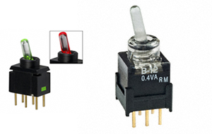
External Interrupt. Users must be able to grab the attention of the console at any time. Momentary push buttons tied to one or more interrupt pins will enable this.
In System Programming. The console has the feature that its software can be maintained and modified in-system. This allows for easy switching of game code.
Reset. A momentary push button will trigger a software reset.
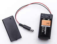
Power. The console will be powered by a 9V battery, the compartment for which will be embedded within the console's case.
The case for the console will contain 2 sections: a body and a cover plate.
The console will have a common body, the design for which will arise from a class discussions on January 16, and 20. Manufacturing of the body in an opaque colour will eventually be outsourced to a 3D printing service.
Given the common specifications for the body, the cover plate will be designed at the partner level. The plate will be laser-cut clear acrylic and secured to the body with screws.
Ergonomic design considerations will be developed at the class level.
Mr. Elia will be here on January 16 and 20 to guide the class through body design decisions and CAD file development. Considerations for the cover plate will also be developed.
Since your game console will attract the attention of others, your console requires a promotional/ product review page. The software parnter will assume the lead for this resource with input and media supplied from the hardware partner.
Partners will collaboarate on video to appear on their web page.
Each student will assemble a comprehensive ER submission having learned the benefit of gathering media elements in parallel with each stage of the development cycle.
Function: Analog to Digital Conversion (ADC) Purpose: Skill level Code: Below is the sample code used in class on December 12 to demonstrate the use of the ADC feature of the Arduino. (Examples > Analog > AnalogInput)
/* Analog Input Demonstrates analog input by reading an analog sensor on analog pin 0 and turning on and off a light emitting diode(LED) connected to digital pin 13. The amount of time the LED will be on and off depends on the value obtained by analogRead(). The circuit: * Potentiometer attached to analog input 0 * center pin of the potentiometer to the analog pin * one side pin (either one) to ground * the other side pin to +5V * LED anode (long leg) attached to digital output 13 * LED cathode (short leg) attached to ground * Note: because most Arduinos have a built-in LED attached to pin 13 on the board, the LED is optional. Created by David Cuartielles modified 30 Aug 2011 By Tom Igoe This example code is in the public domain. http://arduino.cc/en/Tutorial/AnalogInput */int sensorPin = A0; // select the input pin for the potentiometerint ledPin = 13; // select the pin for the LEDint sensorValue = 0; // variable to store the value coming from the sensorvoidsetup() {
// declare the ledPin as an OUTPUT:pinMode(ledPin, OUTPUT);
}
voidloop() {
// read the value from the sensor:
sensorValue = analogRead(sensorPin);
// turn the ledPin ondigitalWrite(ledPin, HIGH);
// stop the program for <sensorValue> milliseconds:delay(sensorValue);
// turn the ledPin off: digitalWrite(ledPin, LOW);
// stop the program for for <sensorValue> milliseconds:delay(sensorValue);
}
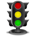
Function:External Interrrupt Purpose: Test User Response
Code: Below is the sample code used in class to demonstrate the use of external internal 0 (Pin 2) feature of the Arduino.
//PROJECT: External Interrupt Example//PURPOSE: Demonstrates the concept of an external interrupt//DATE: December 16, 2013int redPin = 12;
int grnPin = 13;
volatile int red = LOW;
voidsetup(){
pinMode(redPin,OUTPUT);
pinMode(grnPin,OUTPUT);
attachInterrupt(0,isr,RISING);
}
void isr(){
red = !red;
}
voidloop(){
digitalWrite(redPin,red);
digitalWrite(grnPin,!red);
}
The 3D Fireplace. To complement last year's 3D Christmas Tree, you need a 3D Fireplace. Based on the PWM Fire Effect example on page 55 you are to design and implement a unique LED-suimulated fireplace to grace your mantle this holiday season, preferably right beside your tree (the internet doesn't seem to have anything like what I envision so any video contribution you make should spark :) the imagination of others).
A. Concept. Adapt the code supplied with the LED Fire Effect Project (p. 55) referenced above to prototype as realistic a fire effect as you can with the 6 PWM pins available on your Arduino. Enhance your effort with something around the lab that could act as a diffuser.
B. (Optional) Implement your 3D Fireplace. A few common parameters appear below to keep everyone focused.
You will be provided with 6-3mm LEDs that will be driven with the ATmega328 PWM pins. The colour choices are yours from an inventory of red, yellow, amber, green and blue.
You will require a diffuser to cover the LEDs and distribute the flicker. An opaque (coloured?) plastic sheet, waxed paper, a ping pong ball, or frosted plexiglass are viable alternatives. Use your imagination here.
You will be provided with a black plastic project box. I have a couple of different sizes.
You will design and implement a custom circuit board that will be installed in the project box.
Power will be supplied through the 5V regulation of a 9V battery, that will be installed in, or attached to, the project box. Power will be switchable.
The box must be completed disguised. Short lengths of thick twigs, creatively screwed, glued or otherwise affixed to the box will give it a hearth look & feel.
The goal is to provide as much realism as possible, given the materials. Your software decisions, combined with the colours, and diffuser will make the greatest contribution to this feature.
The project is due before you break for the holidays, so get crackling.
Intersection. The first of three major projects this year is to design and build a simulation of a four-way intersection with traffic lights in each direction. Over the course of the project you be introduced to a number of new techniques and the acquisition of these skills will be best served through a series of intermediate deadlines.
A. The Acrylic Cover Plate
Obtain your copy of the ViaCAD download and install/register the application.
While working your way through Mr. Elia's video tutorials, create a 3"×4" rectangular plate with rounded corners, roughly positioned holes at the 4 corners for mounting the standoffs and the 12 LEDs, a possible hole for the On/Off switch and a rectangular cutout for easy access to the microcontroller.
You are asked to have this file prepared for the start of Tuesday's class in which Mr. Elia will be present to field questions and offer advice.
B. The Arduino Prototype
Although you likely have a good idea of how the sequence of traffic lights work it would be highly instructive to consider a similar project generously documented online. Review the (Australian-based) Traffic Light with Pedestrian Crossing Project, thoroughly. From his discussion, value can be gained from the decision path he undertook, his Fritzing diagram and, in particular, a few useful software techniques he employed in his code.
(Recommended) Create an Arduino project entitled PedestrianCrossing and drop in the code supplied by the author. Note: The opening statement should read #include <TimerOne.h> which requires a useful Arduino library that you may have. If you don't, it can be found here. Under the Tools>Board menu select the Arduino Mega 2560 or Mega ADK and confirm that the code will Verify.
Stripping away the pedestrian crossing and adding the NS/EW traffic light pairs, consider what our state transitions would look like by completing the table below using bits (0 or 1) to indicate the status of the LEDs.
State
RNS
ANS
GNS
REW
AEW
GEW
Duration(s)
1
2
and so on...
(Initial) Data Design. Define constants that model the traffic lights and an array (or array of struct) to contain the data.
(Initial) Code Design. The Arduino is comfortable operating at 5V, with each digital pin capable of sourcing 40mA and sinking 50mA. After considering your wiring options, assemble the first draft of the code for your prototpye and test.
C. The Standalone Prototype. With your Arduino-based prototype now functioning, the time has come to move the simulation off-board. Standalone (embedded) electronics are undoubtedly challenging but the incomparable level of satisfaction of seeing a device you conceived, designed, and engineered, functioning remotely, fully justifies the effort.
Arduino UNO
Pin Mapping
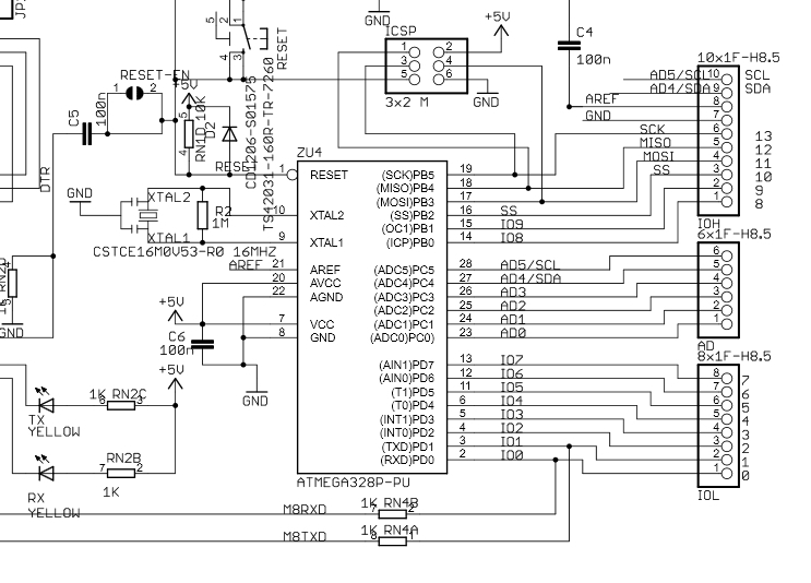
Arduino UNO (Partial) Schematic
Click on the image of the Arduino UNO (above, left) to get a clearer view of the components. Between your UNO and the image, confirm the following about the microcontroller (μC):
Locate the μC and identify the particular model number
What company makes this μC ?
How many pins does the μC have ?
Using the typical reference strategy, where is pin 1 ?
Locate the Receive (RX) and Transmit (TX) pins. What digital pin numbers do these correspond to?
Is the μC soldered directly to the circuit board ?
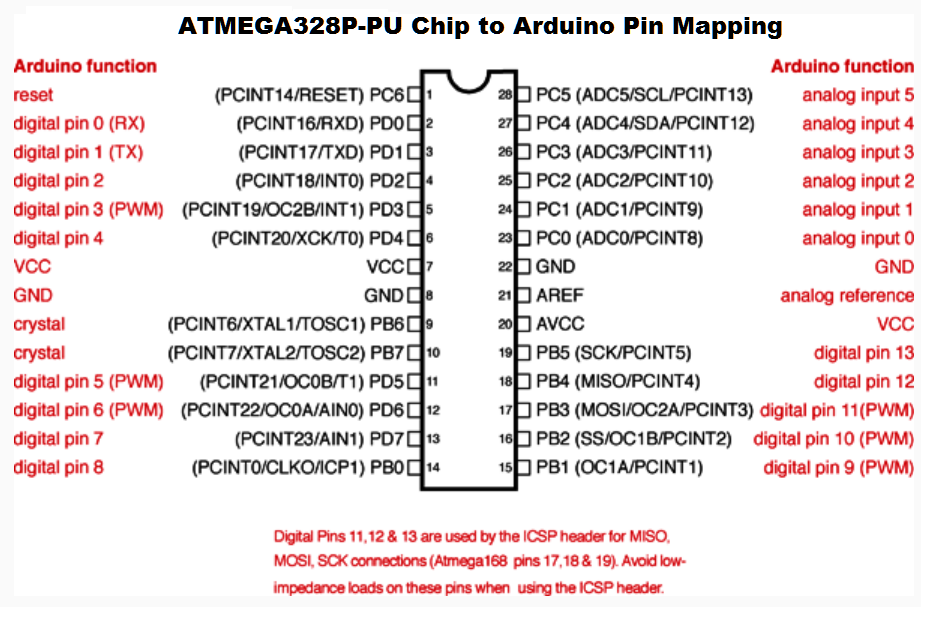
Click on the Pin Mapping image (above, center) to get a clearer view of the function of each of the ATMEGA328-PU pins (black) and how they are mapped within the Arduino UNO platform (red). Confirm the following,
Where is the RESET pin?
Locate the Receive (RXD) and Transmit (TXD) pins. What pin numbers are they?
Where are the power supply pins (VCC and GND) located? How many are there of each ?
Although the μC has an internal clock, it benefits from having an external crystal for timing. What is the name given to the crystal and what pins are used to connect the crystal ?
The Blink sketch that comes preloaded on the UNO, flashes Digital pin 13 every second. Which μC pin is connected to Digital Pin 13 ?
Part of the Arduino UNO's (Partial) Schematic (above, right) to get a clearer view of the ATMEGA328-PU's connection details. Confirm the following,
What is the voltage requirement of the μC and which pins are used for the power supply ?
Where is the RESET pin? Explain how is it configured for operation.
Although the μC has an internal clock, it benefits from having an external crystal for timing. Identify the speed of oscillation and explain, specifically, how the crystal is attached to the μC.
Based on your research above and assuming an ATMEGA328-PU has the Blink sketch in its program flash prepare a Fritzing diagram that displays a complete half+ breadboard view that could be used to wire up a standalone circuit demonstrating a working version of the sketch. Save your Fritzing diagram as StandaloneBlink.fzz.
Attach your Fritzing diagram to an email to handin with the Subject Line: StandaloneBlink by midnight tonight.
(Wednesday) Flash the Blink sketch onto your Arduino.
Unplug your Arduino.
Gently remove the ATMEGA328P from it's chip seat on the Arduino, taking great care not to bend the end pins.
After ensuring that the triple breadboard does NOT have a power supply, strategically place the μC in the breadboard so as to enable easy access to the VCC(5V) and GND power rails.
Using both existing parts from your kit and the additional components supplied to you, assemble your standalone Blink circuit. Build quality counts.
Wire in the 5V and GND supply from your Arduino, before plugging the Arduino back into your laptop.
Confirm the blinking of the LED and the RESET functionality, and show your peers.
(Friday) With the Blink sketch confirmed, the task today is to confirm a working prototype of your full Intersection sketch.
Carefully place the μC back on the Arduino platform, ensuring none of the 28 pins are bent in the process. With due consideration to the location of the digital pins on the ATMEGA328 (digital pins 2 through 8 on one side of the chip, digital pins 9 through 13 on the other), edit your code and upload the Intersection sketch. Confirm it is functioning as expected.
Gently remove the μC from the Arduino, place it back in the triple breadboard, and wire in the 12 LEDs. Confirm the operation and show me the successful execution of your prototype before you leave today.
Begin your ER entry for Sunday (outline below).
D. ER: The Prototype.
Create the next entry in your ER entitled Project 3. The Intersection (your Cover Plate summary will wait until a later submission).
Start with a subsection entitled, Purpose, in which you offer an explanation of the goals of this project as you understand them.
Follow with a Reference section including relevant links and a brief explanation of what they are.
Next, include a section entitled the Prototype in which you provide full details of the steps leading up to the assembly and testing of your Intersection sketch. Include an explanation supported by a completed State Transition table, ATMEGA328P Pin Mapping diagram, Fritzing diagram, Parts Table and media.
E. The Circuit Board.
Under the subtitle, Printed Circuit Board, introduce EAGLE and your use of it in the design of the Schematic and Board views of your Intersection Simulator.
F. The Cover Plate.
Since all holes (mounting and LEDs) have been drilled, you are able to complete your Cover Plate. Make final hole adjustments and add your initials and before submitting the .vc3 file. I will forward them on to Mr. Elia and he will see that they are cut and returned to you. Be as accurate as possible, this is a one-shot undertaking.
G. The Final Product
Extend the previous section to include a thorough documentation (text, images, video) of the manufacturing (printing the mask, transferring to photosensitive copper plate, etching, and drilling) of your PCB. Think creatively.
Once your final testing has been performed and your cover plate has been installed, obtain some final media and add it to your ER. Submit your document to handin and your intersection to Mr. D. for evaluation.
The Bargraph. While this course expects you demonstrate interrelated hardware and software competencies it's only natural that each student would have a slight preference for one over the other. I've designed this collaborative project to allow you to lean towards your personal preference. Each student is free to take on either of the following tasks but is asked to,
Make a significant contribution to their group's effort
ER sections: Purpose, Reference, Procedure, Sketch, Media (photo(s) and a link to your group's video confirmation), and Summary. You decide the content of each section. A premium will be awarded for your inclusion of strategic elements, great code, creativity, and the recognition of the recommendations in the Technical Writing document
Submit to handin by the deadline with the Subject Line: Project 2. The Bargraph
Volunteer to present your group's achievement on Tuesday Oct 8.
Project 2 Groups
Hardware 1
Hardware 2
Software
GT
SB
AK
ME
AE
SC
LD
RS
RF
PW
GB
TG
TH
RS
Hardware Task.
The 4017 Decade Counter takes an input clock pulse on Pin 14 and presents a 10-count on sequential pins. Pin 12 cycles once for every 10 input pulses, presenting a rising edge on the 0 count. Be sure to watch, and understand, the timing diagram animation. Two cascading 4017s, properly wired, can monitor a count of 100 before resetting itself. This count can be presented on a number of display devices. Two bargraphs would work. In the diagram below, the green LED bargraph could display the units' count and the red LED bargraph could display the tens count.
Place the major components on your breadboard similar to the layout below. Using the fixed and resistor networks provided, be sure the LEDs are protected. Cascade the 4017s in such a manner that the two bargraphs present the count as defined earlier.
Develop an elegant, efficient Arduino sketch entitled BargraphTest that drives the circuit. Note: You are not to use for statements, not are you to use if statements.
Obtain video footage of your base 10 counting system.
Rewire your circuit to count in octal. and make slight edits to your sketch. Note: If your coding skill are up to par, you should not have to change any statements in the setup() or loop() functions.
Add footage of your octal counter to that of your decimal counter and upload the content as a single YouTube video.
Software Task.
In the becker.robots library (package), Prof. Becker includes a Robot class. As a result, users are able to instantiate objects of the Robot class without concerning themselves with the specific details of how the class functions. This 'hiding' of functionality and information, referred to as encapsulation, is useful as it allows the software engineer to take problem-solving to a higher level of abstraction. In this task, you are asked to write a Bargraph class that will allow authors of future sketches involving bargraphs to focus less on the device details and more on the data being manipulated. The Arduino language is based on C++ syntax. Writing a library gives you useful experience for what may lay beyond RSGC.
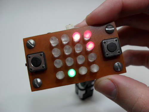
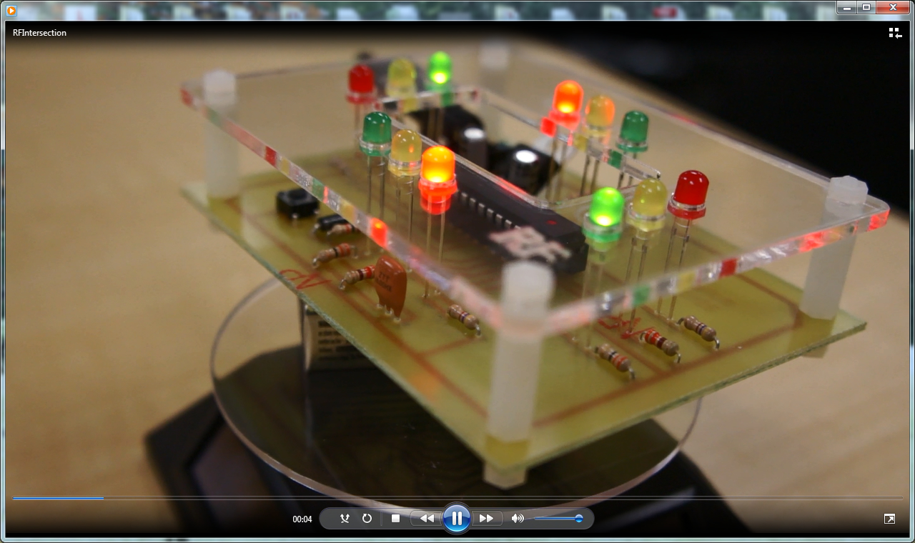
View a video sample of the goal of this project:
Match the results of the video with the Arduino sketch used create the display: BargraphLibraryTest.ino
Collaborate with the other group members on the development of a common UML diagram defining a Bargraph library to meet the minimal requirements of sample driver sketch: BargraphLibraryTest.ino and provide additional creative functionality (justify any redesign of the Bargraph library suggested by the driver). Be sure to include the common UML diagram in each of your ERs.
In addition to the .h and .cpp library files here is an explanation of the value and structure of the keywords.txt file.
Develop and upload the 'javadoc' for the Bargraph library to each members' F/C Web Publishing folder. Include a link from your ER.
Using the sketch provided as a starting point, add more statements to exercise two or more additional functionalities of your (common) Bargraph Library.
Seven-Segment Display. The first entry in the TEI3M section of your ER is a summary of the reproduction of last year's exam from the Arduino platform, with a twist.
Task.
Modify the sketch you developed for the CIRC-01 Day 4 Mod to include ALL of the hexadecimal digits.
Add TEI3M after TEL3M on the cover page of your ER.
Insert a new full (odd) page in your ER with TEI3M: Computer Engineering Technology, Emphasis: Interfacing. Starting on the next odd page after that, complete the Project entitled, Project 1. Seven-Segment Display.
Include the following sections, Purpose, Reference, Procedure, Sketch, Media, and Conclusion. You decide the content of each section . A premium will be awarded for your inclusion of strategic elements, great code, creativity, and the recognition of the recommendations in the Technical Writing document (a link to video displaying your continuous sequence would surely be an asset).
Submit to handin by the deadline with the Subject Line: Project 1. Seven-Segment Display
 Individual Project (each student is responsible for both the hardware and software requirements of their clock)
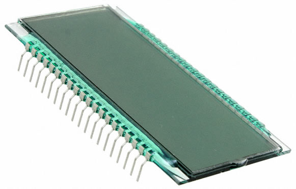 Microcontroller-based: Mega or Tiny
 Digikey: http://www.digikey.ca/
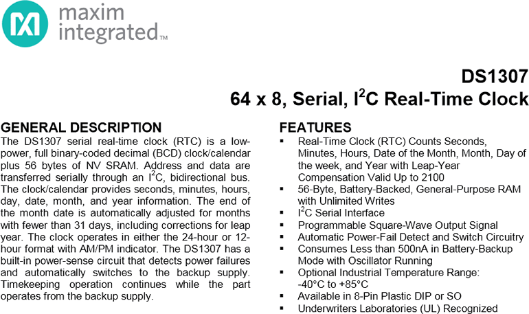
 Although you've done this a couple of times this year (Intersection & Console), there are a few new considerations for this project.
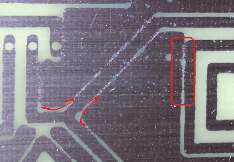 In attempting to limit the sizes of your boards, you may have to monitor the width of your gaps. If they are too narrow, etching may not be able to remove the copper as can be seen by the adjacent, unsuccessful attempt. An hour and a half did little to remove the copper in the gap and, inadventently started overetching other areas.
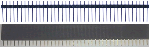
 PCB Fabrication (Wednesday Feb 19 though Friday Feb 28). We have all invested a great deal of time, effort, skill, and money to get to this point, so there is a lot at stake beyond just a mark. This is more about the present and lasting pride of accomplishment. You get one shot at this. If you think deeply, bring all your previous engineering experience forward, double- and triple-check your work, with your partner, and others, you will enjoy a successful outcome. As an incentive for being the best you can be, only fully-functioning boards will be awarded a console case.
 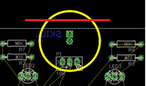 Be sure your outer board dimensions are EXACTLY 4" by 3" BEFORE placing any parts and keep an eye on it.
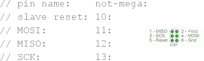 Function: In-System Programming.
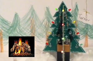
 Although you likely have a good idea of how the sequence of traffic lights work it would be highly instructive to consider a similar project generously documented online. Review the (Australian-based) Traffic Light with Pedestrian Crossing Project, thoroughly. From his discussion, value can be gained from the decision path he undertook, his Fritzing diagram and, in particular, a few useful software techniques he employed in his code.
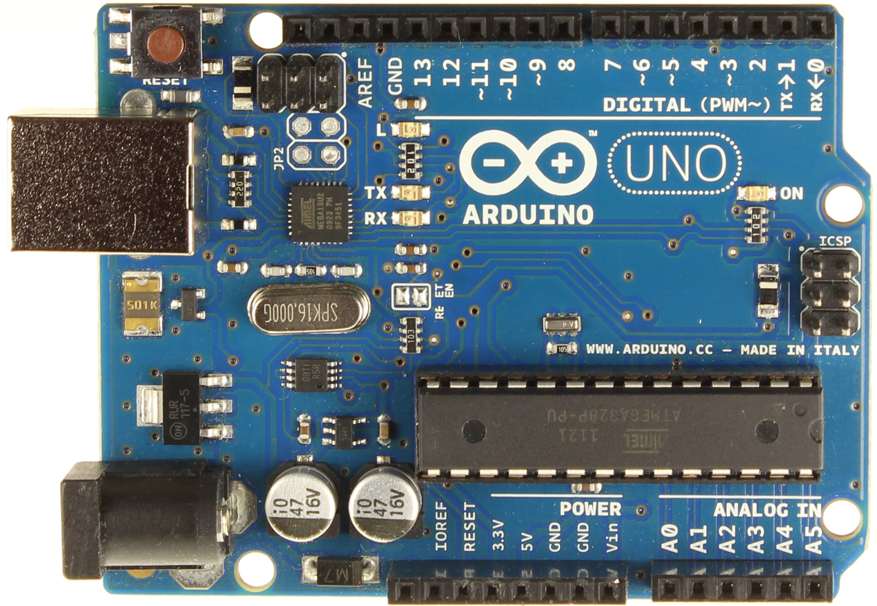
 Since all holes (mounting and LEDs) have been drilled, you are able to complete your Cover Plate. Make final hole adjustments and add your initials and before submitting the .vc3 file. I will forward them on to Mr. Elia and he will see that they are cut and returned to you. Be as accurate as possible, this is a one-shot undertaking.
 The 4017 Decade Counter takes an input clock pulse on Pin 14 and presents a 10-count on sequential pins. Pin 12 cycles once for every 10 input pulses, presenting a rising edge on the 0 count. Be sure to watch, and understand, the timing diagram animation. Two cascading 4017s, properly wired, can monitor a count of 100 before resetting itself. This count can be presented on a number of display devices. Two bargraphs would work. In the diagram below, the green LED bargraph could display the units' count and the red LED bargraph could display the tens count.
 Modify the sketch you developed for the CIRC-01 Day 4 Mod to include ALL of the hexadecimal digits.
