Perform the following hardware and/or software modifications to have the respective circuit exhibit the required behaviour. Be sure to confirm.
NOTE. The goal this year is to write great code, not simply code that works. Likewise, the build quality of your prototypes continues to command a premium as it did in Grade 10.
 CIRC-01. Blinking LED.
- Day 1. Review the Blink code carefully. Retype the sketch from memory under the name BlinkMod within a folder entitled Arduino. Add comments.
- Modify the circuit resulting in a count that it twice as fast. Think about great programming style.
- Modify the circuit to have the pulse originate from a different pin.
- Modify the circuit to place control of the up/down counting under software direction.
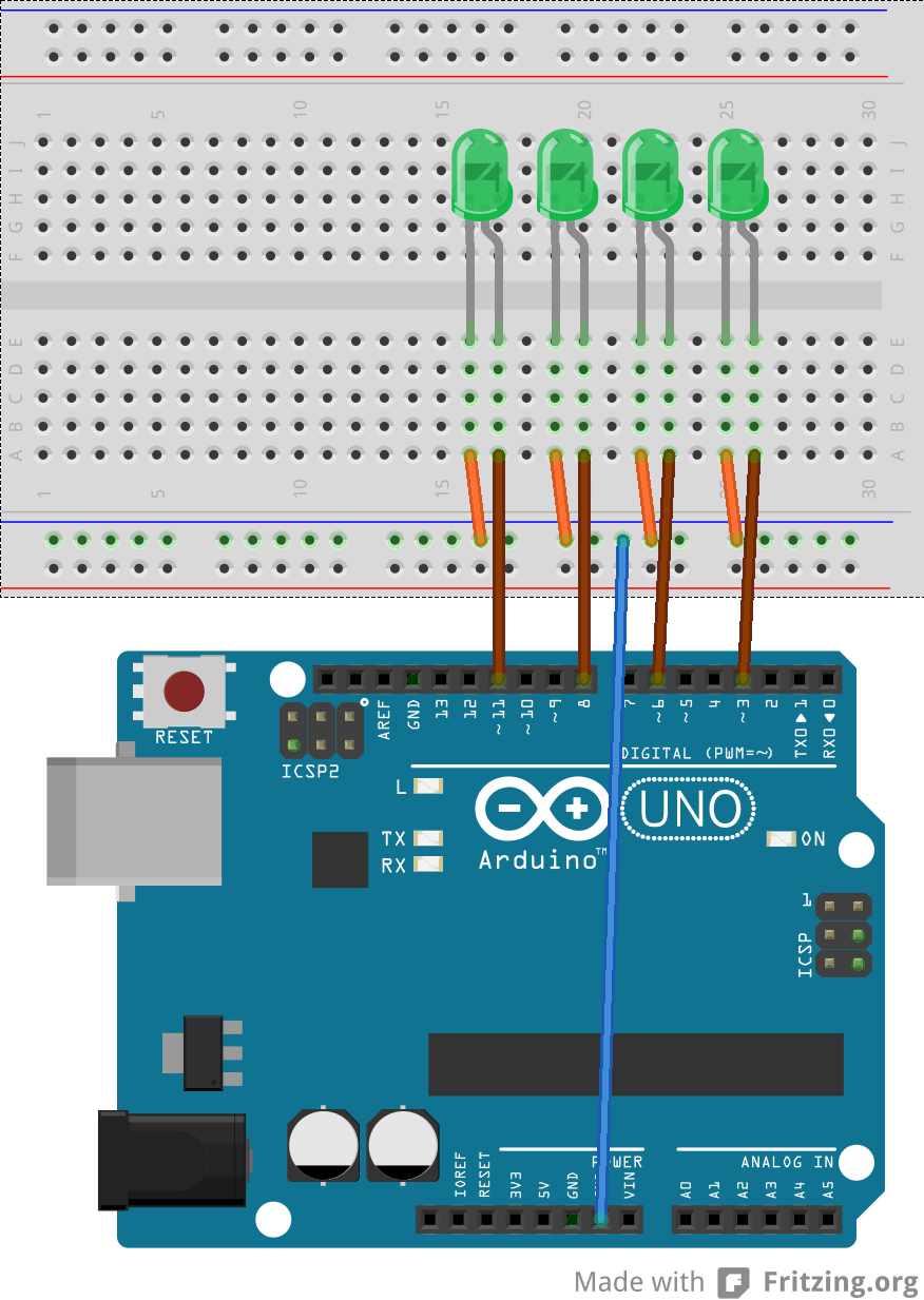
- Day 2. Duplicate the Fritzing breadboard view shown to the right (click the image to enlarge if necessary) and save the file as NybbleCounter.fzz.
- With the 4516 BCD IC removed, it's up to the software alone to present the counting. Develop the Arduino sketch NybbleCounter.ino that counts up from 0 through 15 before rolling over to 0, continually.
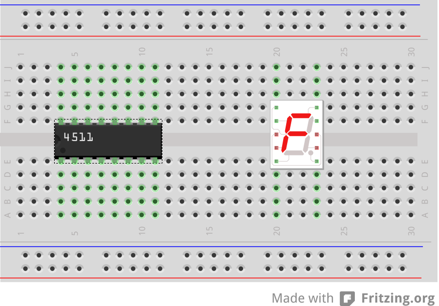
- Day 3. With the Arduino software now performing the role of the 4516, we can accomplish the same result as last year's exam with only the 4511 BCD to 7-segment display driver, appropriate resistors, and a 7-segment display. Save your working NybbleCounter.ino sketch as BCDtoDisplay.ino and modify it to drive a breadboard setup
similar to the following,
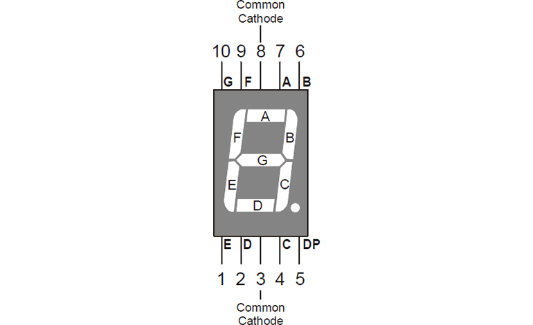
- Day 4. (Updated: Sep 20) The final modification of last year's exam is to drive the 7-segment display directly from the Arduino (with resistors of course). Clearly, you'll need to employ 7 digital pins.
- Create a sketch entitled SevenSegmentDisplay.
- Representing each decimal digit requires the code to light the correct combination of segments, A through G. Use a table similar to the one below to identify the correct segments for each digit.
| 0 |
1 |
1 |
1 |
1 |
1 |
1 |
0 |
B01111110 |
0176 |
0x7E |
| 1 |
0 |
1 |
1 |
0 |
0 |
0 |
0 |
B00110000 |
0060 |
0x30 |
| 2 |
1 |
1 |
0 |
1 |
1 |
0 |
1 |
B01101101 |
0155 |
0x6D |
| 3 |
|
|
|
|
|
|
|
|
|
|
| 4 |
|
|
|
|
|
|
|
|
|
|
| 5 |
|
|
|
|
|
|
|
|
|
|
| 6 |
|
|
|
|
|
|
|
|
|
|
| 7 |
|
|
|
|
|
|
|
|
|
|
| 8 |
|
|
|
|
|
|
|
|
|
|
| 9 |
|
|
|
|
|
|
|
|
|
|
- Using the array declaration below, complete the remaining 7 constants in either binary, octal, or hexadecimal values for efficient storage and access.
int segments [] = {B01111110,060,0x6D,?,?,?,?,?,?,?};
- Implement a function with the header below that is to be called to light the 7 segments for a single digit passed as a parameter,
//This function lights the appropriate segments for the digit n
void display(int n){
 ...
}
- Complete and confirm your sketch, combining your own coding strategies with the best idea understand from here.
- The cyclical display in last year's exam eventually came to rest due to the discharging of RC1. Although you needn't pursue it now, you should consider how the code in your sketch might simulate this behaviour over a random duration.
- Finally, you should consider whether the Arduino is capable of meeting the power requirements of this task. In particular the current demands for each pin and the entire board in total. You also want to imagine how an Arduino could be used to drive multiple 7-segment displays.
 CIRC-02. Multiple LEDs.