| RSGC ACES Standalone ATmega328P Tutorial (Dec. 2012) |
NOTE: Despite what all the sites say, this process is tricky. The majority of the authors will say its simple, but, believe me, they struggled for hours before they got it right. The components change all the time and/or they use specific devices and/or they typically leave out one step. So, after my own attempts, here's what I've managed to distill it down to.
Objective: To develop a standalone ATmega328P for use in embedded circuits (as in the Gravimeter project)
Parts include an Arduino UNO R3 and a few raw ATmega328P-PUs.
Part 1. Burning the Bootloader
The optiloader sketch (https://github.com/WestfW/OptiLoader) will automatically recognize a variety of microcontrollers (ATmega8, ATmega168, ATmega328, ATmega328P) and efficiently burn the bootloader to as many devices as you need. This is a one time burn. If you try to burn the bootloader again to the same device it will fail. The ATmega328P stays in the Arduino. Note: The Arduino's uC remains in the unit. Just open optiloader.pde and upload the sketch as usual. The bootloader will be burned to the blank 328P on the breadboard. (Note: I burned the entire lot of 328Ps I have and marked each one with a red dot). Here's a wiring diagram from this tutorial,
Part 2. Uploading a sketch from the UNO to the (bootloaded) breadboarded ATmega328P-PU.
Although there's probably a way to upload a sketch using the PC/USB/Arduino to the breadboarded ATmega328P without removing the uC on the Arduino, I wasn't able to find one. So, remove the uC from the Arduino and wire it up as the image below taken from this tutorial suggests.
Confirmation
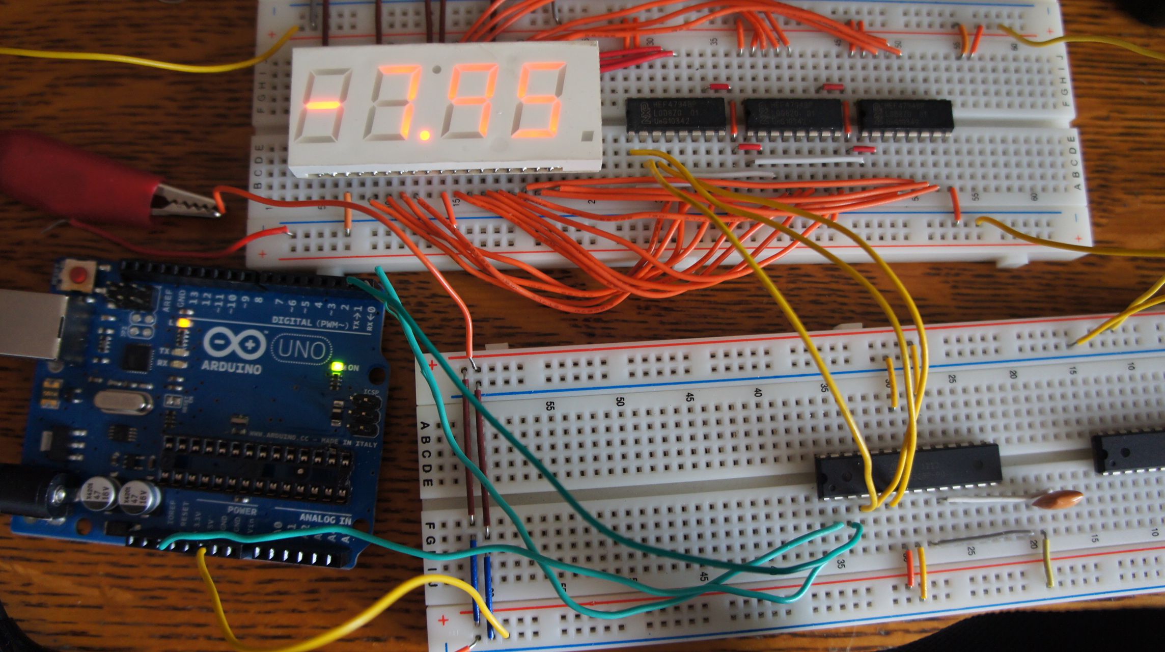
Below is an image after a successful upload of the sketch that cycles a sequence from 0.00 to 9.99 to the HEF4794B shift registers/LED Drivers. Note the 16 MHz resonator attached to pins 9 and 10. The resonator replaces the 16 MHz crystal and 2-22pf capacitors.