 Project 4. Independent Study Project. The ISP is an opportunity to explore an area related to electric circuits that you find compelling. In addition to the knowledge and skill you will gain, you will confirm the depth of your interest and passion for this subject area. Furthermore, this experience will inform your course selection decision-making process.
A recent post to our subject conference summarizes your peers thoughts on what makes for a good ISP. This list should be considered when selecting a area for investigation. Our ACES' ISP page should also be reviewed for a more comprehensive overview of the rationale and philosophy of this undertaking.
For the ER submission of your ISP you are asked to follow the general outline of previous ER reports. The highest credit wil lbe reserved for those Reports that offer a comprehensive summary of the entire process, starting with project selection, the development stages that blend text, images and links to crtitical components. Finally, a well-planned, tightly-coordinated summative video and conclusion will round out the submission perfectly. Nick Jones' summative video of his TEL3M ISP a year ago was one of the best in recent memory  LED Music Box (be inspired but do not duplicate)
Address, but do not remove, the concerns expressed
in ALL my comments embedded in your ER.docx from the last submission.
Submit your final ER.docx as
an attachment to an email to handin with the Subject Line: Independent Study Project by midnight on Monday May 23, 2016.
 Project 3. NAND Gate Oscillator.
Your second-to-last ER entry for this course will start on the first new page after
Project 3. NAND Gate Oscillator.
Your second-to-last ER entry for this course will start on the first new page after
Project 2. Digital (Transistor-Based) Logic Gates, with the page orientation restored to Portait and the tab stops in the header adjusted accordingly.
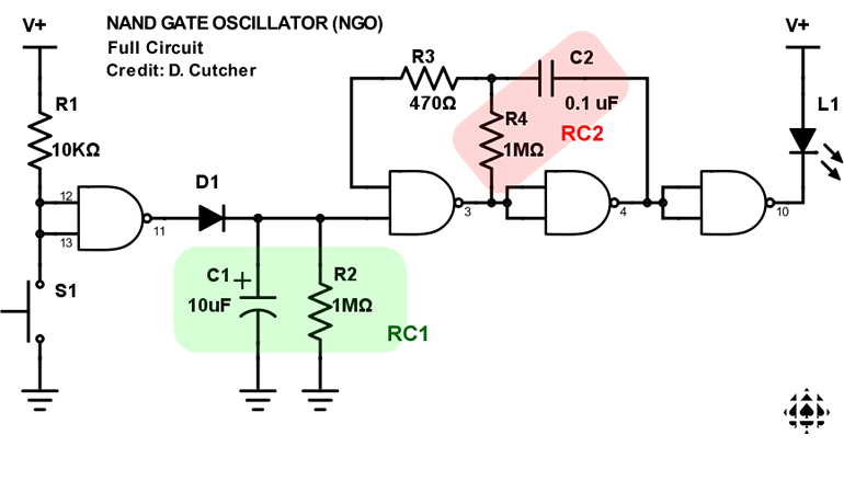
You are asked to provide a detailed report on the stages of the NAND Gate Oscillator leading up to, and including, the Full Circuit that appears below. See below for specific ER requirements.
 Task.
Task.
- Use the title, Project 3. NAND Gate Oscillator in Heading 1 style.
- Subsections in Heading 3 Style that include, Reference, Procedure, Parts List, Media (photos, video), and Conclusion. All sections, with the exception of the Conclusion, are written in the Active Voice (not first, second or third person). See the Guide to Technical Writing if you are still unsure of how this is done. You Parts List will use cell shading consistent with previous tables in your Report.
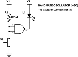
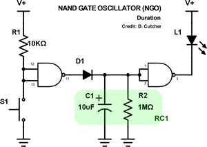
- The Procedure Section should first provide your overview of the design on the 4011 Quad, 2-Input NAND gate with a supporting pin diagram, before covering the three distinct stages of the circuit: The Input, Duration, and Frequency.
- One of the most important aspects of this submission requires you to run experiments for SIX R4 and C2 combinations (R: 2.2MΩ, 4.7MΩ, and 10MΩ ; C: 0.1μF (104) and .01μF (103)) performing THREE trials for each combination by counting the number of flashes over a 10 second interval, before determining the average (Note: If you pull R2 from RC1 you can can more easily observe the flashes without the circuit timing out). Summarize ALL of of the data from your trials in a well-formatted table.
-
 Support your text with a strategic and liberal selection of graphics and photos of your choice, formatted impeccably as discussed earlier in the course.
- Be sure to have addressed all previous review comments and issues flagged in the previous Feedback emails to our First Class TEL3M conference.
- Finally, ensure your Table of Contents has been updated and the page numbering is correct, prior to submission.
Submit your ER to handin before
midnight on Saturday May 14, 2016.
 Project 2. Digital (Transistor-Based) Logic Gates. For this submission you are asked to,
 Merge the Word document, InsideGates, into your ER on the first page after Project 2, retaining the landscape orientation of the document. Be sure to format all the requirements below into this single page, scaling as necessary, but retaining maximum readability.
- Ensure your ER header and footer elements run through the page, adjusting the tab stops as necessary to accommodate landscape orientation.
- Set the title to your Heading Style.
- Adjust the cell shading to be consistent with your previous preference.
- Complete the Fritzing Schematic Name, Symbol, and Truth Table for each of the remaining three transistor-based gates. Do NOT make any mistakes; it's too important!
- Be sure to update your Table of Contents prior to submission.
: P-CA, QC, DC, RG, CG, GG, WK, OL, JLong, JLow, AMcD, AM, EM, SO, OP, JS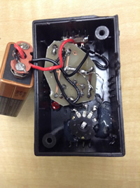
Project 1. Automatic Night Light. This is a major project in that after a successful prototype build on your breadboard you will assemble a permanent version by soldering the components to the custom printed circuit board in your kit. After that, you will mount the unit in a project box. Since you will be submitting a full ER entry for this project, you will document the build process with photos and video as it evolves. (Another objective of this project is to start you thinking about your personal ISP project that will require you to research/envision a circuit to build, assemble, and present)
Your writeup for this Project will include,
- Purpose, Reference and Procedure subsections (Heading 3 Style) with appropriate content.
- Fritzing schematic view of Circuit 4.1.
- Fritzing breadboard view of Circuit 4.1 adjacent to a photo of your prototype
- Clear photos of front and back of your soldered PCB
- Consider the Test Point shown in Red below. With your DMM, obtain and record voltage readings for the various settings described below. Incorporate the measurements into full sentence, hanging indent-laden, responses to
the questions that follow.

- Set the pot to 0 Ω (wiper C all the way to A) and under fairly good light, measure and record the voltage at the Test Point.
- Now, obscure the LDR completely with a heavy dark covering and take another voltage reading. Explain the difference.
- Adjust your pot to 50k Ω (wiper C halfway between A and B) and repeat the previous two measurements. Record and discuss the results.
- Finally, set your pot to its full 100k Ω setting (wiper C all the way to B), and repeat the two measurements one last time. Record and explain your results.
- Photos and a video of the complete circuit development process and result in action.
Address, but do not remove, the concerns expressed
in ALL my comments embedded in your ER.docx from the last submission.
Submit your ER.docx as
an attachment to an email to handin with the Subject Line: Automatic Night Light
Additional photos of Mariano's build: ANL4, ANL5, ANL6, ANL7, ANL8, ANL9
