Microsoft Word Reference Guide
As further evidence of your evolving technical competency, all of the formal projects you will be assigned are to be submitted
as additions to an evolving Word document called your Design Engineering
Report. Since Engineers need to be able to communicate effectively, typically to an audience that is unfamiliar with many of the concepts, use this opportunity to develop your writing skills. Be sure you are familiar with the recommendations of this Technical Writing document. Here's Wikipedia's take on Technical Writing. As challenging as it will be at first, with the exception of the Reflection section at the end of each summary, Technical Reports are NOT written in the first, second, or third person. The focus is on the use of the Active voice. Here's a good example from a recent Grade 12 report, written in the present tense, and the components are the subject performing the action (Active Voice),
Three AND gates, two inverters, and two OR gates are used to tie both modes of the clock pulse together into one single output line. The select output and the adjustable pulse line go into one AND gate.
By each submission
date, you will attach your updated DER.docx to an email to ACESHandin@rsgc.on.ca using the required Subject Line.
Using potentially ALL of your word processing skills (fonts,
styles, page margins and paragraph indents, headers, footers, page numbering,
lists, tables, Equation Editor, etc.), your DER
will consist of,
- First, open Word and ensure your units of measure are inches and the Normal Style font is Times New Roman, 11pt.
- Create a new document and save it as DER.docx. Create a cover page with the title (Design Engineering Report), the course name
and code, your name, and the current date (set to update automatically), formatted using Movie Credit-style tab stops. See Exemplar.
- Create a Table of Contents, updated with EACH submission.
- Project Report summaries typically include the following common subheadings
(Purpose, Reference, Procedure, Media,
and Reflection). Do NOT place a colon at the end of each subheading.
 A right-aligned Parts Table will appear in the Procedure section, with center-center cell alignment and alternate background shading. This style is to be used throughout ALL of your Project summaries. See Exemplar.
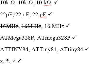
- The formatting of units for components, both in your Parts Table AND body text, MUST follow convention!
- Project titles in Heading 1 Style
- Project subheadings (Purpose, Reference, Procedure, Media, Reflection) appear in Heading
2 Style
- All Project titles and subheadings are to remain left-aligned. General body Paragraph shape is left aligned, ragged right. Do NOT indent the first sentence of each paragraph.
- Write in sentences and paragraphs, avoiding orphans. Long tracts of runon sentences and paragraphs will reduce your credit.
- Consistency is the key. ALWAYS use the Word's Insert Tab for the formal inclusion of images, photos, tables etc. using the context-senstive Design and Format tabs that pop up to edit the object to 3" in width, typlcially and various other features. Students that simply drag objects in their Reports will see their document grow larger and their mark grow smaller. Remember, your Grade 10 DER should remian under a maximum 1MB limit.
 Hyperlinks. The actual full URL must appear as a live link. You present https://www.youtube.com/embed/M0SSI3rKYbw. Do NOT present links like My Video.
- Spelling and grammar issues reduce your credit, as do unaddressed feedback comments from report to report.
- Tables, especially with 3 columns or less will ALSO adhere to the 3" width standard. Tables with many columns can span the entire page width (6.5") and center-aligned within their own paragraph if needed.
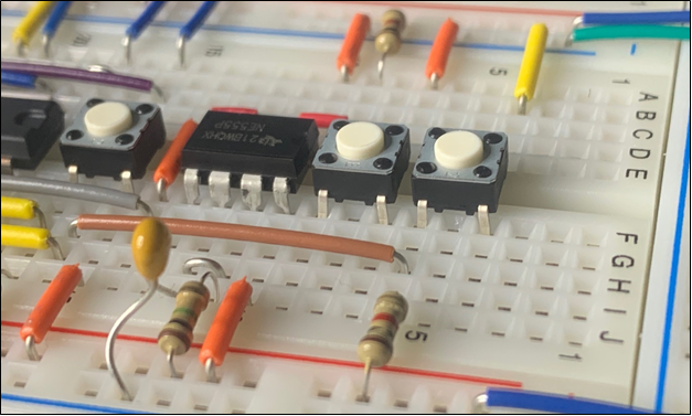
- The 3" graphics and tables described above WILL have square text-wrapping and right-aligned (without spilling into ANY margin), just as the Fritzing image appears above.
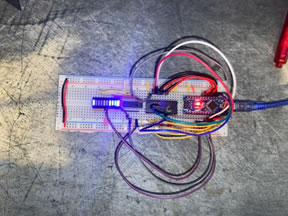
- Even my 12s submit poorly composed photos form time to time as the image to the right confirms. Some things I just can't teach.
- Where two complementary graphics (like the front and back views of a circuit board) are included, they should be sized to 3" wide as described above, but placed within a two-column, captioned, full-width, borderless table, with center and top cell alignment declared. See the example below of from recent DERs. The two high-quality photos with a 1px border on each are presented in a 2-row, 2-column borderless table. The first row contains a meaningful caption.
- Use of the correct symbol (eg. Ω) typically inserted from the Symbol Table, is
expected at all times.
- Project Video summaries are mandatory. ACES will open their own YouTube channel. Do not upload content using your RSGC Google account as these videos will not be available to you after graduation. Compose and upload videos of their working circuits and provide a link from the Media section of the Project writeup. Videos are,
- planned and organized ahead of time with a focus on teaching as well as demonstrating
- grab a nice pencil, cool Japanese chopstick, or proper telescopic stainless steel pointer (<$10)
- filmed with a stable camera in a fixed position unless absolutely necessary to move
- set your camera to Manual focus (not AutoFocus) so it doesn't bounce around when you're moving your pointer in, around, and out of the shot
- filmed in LANDSCAPE orientation, not portrait
- to be designed to convince your audience that you know what you're talking about and you're going to teach them something
- to have a meaningful script that has you narrating the details of your project
- to be kept to a MAXIMUM of 2 minutes in length
- to START with a DEMONSTRATION of the WORKING prototype, followed by a detailed explanation (having a schematic to go through is effective). This order works best to keep the audience interested
- NOT to have any background music
- to be filmed using the highest quality, closeup, STABLE camera you have access to. Your prototype should remain as stable as possible when filming, where appropriate. A pen, pencil or pointer is superior to your finger in drawing your viewers attention to components and connections.
- Look for the videos that I mark with a single (or double!) asterisk; They contain some masterful elements.
Finally, a commitment to developing your Word skills through your Design Engineering Report will pay big dividends in other courses as the quality of your submissions will improve noticeably and your teachers will take note of your emphasis on the quality of presentation.
| M. Zischka's D-Latch Memory Circuit |
O. Kunica's Power Diode Measurement |
 |
 |
Technical Writing: Don'ts and Dos (Active Voice, Present Tense, Concise)
For this project I used 5 capacitors. You'll see them listed in the part list to the right. |
The 5 capacitors used in this project are listed in the parts list table to the right. |
In my circuit, I used 4 resistors. There are two 470 ohm resistors, one 220 Ohm resistor and a potentiometer. |
A total of 4 resistors are used in this circuit. There are two 470 Ω and one 220 Ω fixed resistors and a potentiometer, acting as a variable resistor. |
In this project we were asked to demonstrate how transistors can be used to provide a steady heartbeat for an LED through an analog oscillator. |
The purpose of this project is to demonstrate how transistors can be used to provide a steady heartbeat for an LED through an analog oscillator. |
During this project, we were required first prototype our Analog Oscillator, and Breathing LED, then we were required replicate them onto a permanent board and solder our circuits to them. |
After completing a prototype on the Analog Oscillator on a breadboard, transfer the circuit to a permanent circuit board for soldering. |
First, I took the Heat Shrink Tubing and cut it into 5 pieces of equal length using the pliers. |
Cut the heat shrink tubing into 5 pieces of equal length. |
* In February 2019, G. Benson recommended we change the name of our project document from ER.docx to DER.docx to reflect the inseparable relationship between great design and great engineering. I couldn't agree more. Here's a excerpt from his email,
"As I sit here with my four printed copies of my ER ready to head with me to USC tomorrow, I have had a bit of an epiphany. Effective as of my next submission, I would like to change the title of my report to "Design Engineering Report". So much of what we do in the ACES reflects this title, from better wiring, to CAD casing, to Eagle PCB creation. It is very true to our roots. It also happens to nicely fit in with our 'Design Engineering Studio.' I believe the future of ACES involves students handing in their DERs on Saturdays."