(Cancelled) Project 5. Final Exam. Your final ER entry for this course will start on the first new page after your ISP Report and appear under the heading Project 5. Final Exam.
 The title, Project 5. Final Exam in Heading 1 style.
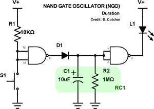
- Subsections in Heading 3 Style that include, Reference, Procedure, Supplemental Parts List, How It Works, and Media. The How It Works section should begin by explaining, in detail, the role played, by the NAND Gate Oscillator up to, and including, Pin 10 of the 4011. Following that, include a discussion of the 4017 Decade Counter that receives the clock pulse from Pin 10 of the NGO as input and what it does with that signal. Finally, include a discussion of the how the additional components of the exam fit into thew system.
- Support your text with a strategic and liberal selection of graphics of your choice taken from the exam and/or our course page, if necessary, formatted impeccably as discussed earlier in the course.
- Be sure to update your Table of Contents prior to submission.
You do not have to submit this effort until 10:00 pm on January 21, 2016.
 Project 4. Independent Study Project. The ISP is an opportunity to explore an area related to electric circuits that you find compelling. In addition to the knowledge and skill you will gain, you will confirm the depth of your interest and passion for this subject area. Furthermore, this experience will inform your course selection decision-making process.
A recent post to our subject conference summarizes your peers thoughts on what makes for a good ISP. This list should be considered when selecting a area for investigation. Our ACES' ISP page should also be reviewed for a more comprehensive overview of the rationale and philosophy of this undertaking.
For the ER submission of your ISP you are asked to follow the general outline of previous ER reports. The highest credit wil lbe reserved for those Reports that offer a comprehensive summary of the entire process, starting with project selection, the development stages that blend text, images and links to crtitical components. Finally, a well-planned, tightly-coordinated summative video and conclusion will round out the submission perfectly. Nick Jones' summative video of his TEL3M ISP a year ago was one of the best in recent memory  LED Music Box (be inspired but do not duplicate)
Address, but do not remove, the concerns expressed
in ALL my comments embedded in your ER.docx from the last submission.
Submit your final ER.docx as
an attachment to an email to handin with the Subject Line: Independent Study Project by 10:00 PM on January 21, 2016.
Project 3. Digital (Transistor-Based) Logic Gates. For this submission you are asked to,
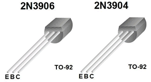 Merge the Word document, InsideGates, into your ER on the first page after Project 2, retaining the landscape orientation of the document. Be sure to format all the requirements below into this single page, scaling as necessary, but retaining maximum readability.
- Ensure your ER header and footer elements run through the page, adjusting the tab stops as necessary to accommodate landscape orientation.
- Set the title to your Heading Style.
- Adjust the cell shading to be consistent with your previous preference.
- Complete the Fritzing Schematic Name, Symbol, and Truth Table for each of the remaining three transistor-based gates. Do NOT make any mistakes; it's too important!
- Be sure to update your Table of Contents prior to submission.
: OB, MB, SC, KC, MC, DD, BD, EH, DH, TM, EP, MR, ASP, JSS, NT, MT
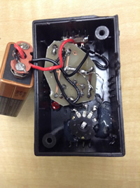
 Project 2. Automatic Night Light. This is a major project in that after a successful prototype build on your breadboard you will assemble a permanent version by soldering the components to the custom printed circuit board in your kit. After that, you will mount the unit in a project box. Since you will be submitting a full ER entry for this project, you will document the build process with photos and video as it evolves. (Another objective of this project is to start you thinking about your personal ISP project that will require you to research/envision a circuit to build, assemble, and present)
Your writeup for this Project will include,
- Purpose, Reference and Procedure subsections (Heading 3 Style) with appropriate content.
- Fritzing schematic view of Circuit 4.1.
- Fritzing breadboard view of Circuit 4.1 adjacent to a photo of your prototype
- Clear photos of front and back of your soldered PCB
- Consider the Test Point shown in Red below. With your DMM, obtain and record voltage readings for the various settings described below. Incorporate the measurements into full sentence, hanging indent-laden, responses to
the questions that follow.

- Set the pot to 0 Ω (wiper C all the way to A) and under fairly good light, measure and record the voltage at the Test Point.
- Now, obscure the LDR completely with a heavy dark covering and take another voltage reading. Explain the difference.
- Adjust your pot to 50k Ω (wiper C halfway between A and B) and repeat the previous two measurements. Record and discuss the results.
- Finally, set your pot to its full 100k Ω setting (wiper C all the way to B), and repeat the two measurements one last time. Record and explain your results.
- Photos and a video of the complete circuit development process and result in action.
Address, but do not remove, the concerns expressed
in ALL my comments embedded in your ER.docx from the last submission.
Submit your ER.docx as
an attachment to an email to handin with the Subject Line: Automatic Night Light
Additional photos of Mariano's build: ANL4, ANL5, ANL6, ANL7, ANL8, ANL9
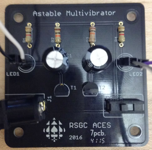
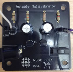 Project 1. Astable Multivibrator. Cole Norton (RSGC '14), prepared and delivered a workshop for interested Georgians in his graduaiton year on a recreational application of an analog oscillator that could be used to create blinking eyes in a Halloween pumpkin. Cole's legacy of having Jr. ACES 'pimp their pumpkins' each Halloween has been kept alive by RSGC '15 ACES (R. Saunders, G. Trusler, A. Ettehadieh, and M. Elia) and advanced to the point that you now have a customized printed circuit board (right) to support this rewarding activity.
Task.
- Clean the lens of your phone's camera, as you will be gathering media (photos and videos) throughout this project, from start to finish, in support of your ER project summary due Sunday November 1.
- This project will test your organizational abilities as much as your nascent electronics' knowledge and skills. You have been supplied with a bag containing a sufficient number of parts to prototype this circuit. Part of the task includes thinking deeply about what you're doing. In support of this aim please be aware that replacement parts will not be supplied by me.
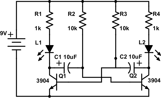
- After studying the schematic of this oscillator circuit (below, left), and reviewing the parts list on page 2 of Cole's handoutundertake your prototype of the analog oscillator (aka, blinker, Astable Multivibrator) on your breadboard. When you are confident the circuit has a chance of functioning, apply 9V power. Debug as necessary and document the results with your phone's camera.
You may wish to experiment with the rate at which the LEDs are flashing by adjusting the sizes of the resistors.
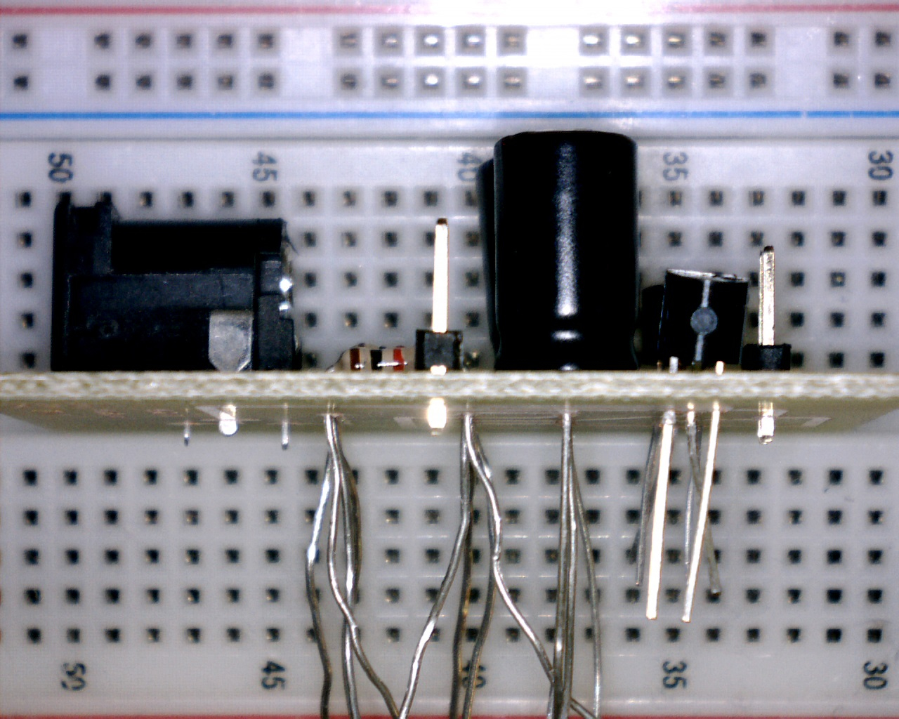
- Once you have obtained your media, you can request the additional parts that include a printed circuit board (PCB), a DC power jack, two pairs of male header pins, and two 3" paired wires. Disassemble your prototype and 'dry fit' the parts on your PCB (above right) in a manner similar to the image to the right (click to enlarge). This is an important step to appreciate the full scope of the task that lies ahead and to avoid the risk of soldering parts incorrectly that can be difficult, or near imposssible, to repair.
- With your soldering area fully equipped with easy access to the required tools and conscious of the soldering techniques and strategies discussed in class and in this soldering video, you may begin the soldering stage. Remember,
- Never solder with the power plugged in.
- Your soldering station should be kept no higher than 300°C.
- Keep the parts as tight to the surface of the PCB as possible. The reverse tweezers can help with this.
- The soldering tip should be clean and tinned.
- Any longer than 4s with the soldering tip on the leg of a component runs the risk of damaging the part!
- Solder the smaller components first: resistors, then transistors, then pin headers, then DC jack, and finally the capacitors.
- On multi-legged semiconductors, it is good practice to solder one leg, solder another part, then return to the original part. This practice minimizes the cumulative heat effect on parts.
- If you have invested care and thought into your efforts, plugging your 9V adapter into the DC Power Jack should yield the desire outcome: a pair of blinking lights. If it doesn't function as expected, prepare yoursefl for the best part: debugging. Seriously, nothing is as rewarding that analyzing and repairing a faulty system. Use the large illuminated magnifying glass to check all your solder joints. Confirm your polarized parts are in the correct way. Use the DMM to to perform continuity, voltage, and integrity inspections. You'll find the problem without the need to ask my opinion.
- ER. Starting on a new page, add the Project name and complete sections under the subheading: Reference, Purpose, Procedure, Media, and Conclusion. Text is developed in accordance with the recommendations for Technical Writing and reflective your strong formatting abilities. Graphic manipulation is undertaken according to the specifications laid out in the Engineering Report General Guidelines.
- Attach your ER to an email to handin with the Subject: Astable Multivibrator by the deadline.