| 2020-2021 ICS4U-E Tasks |
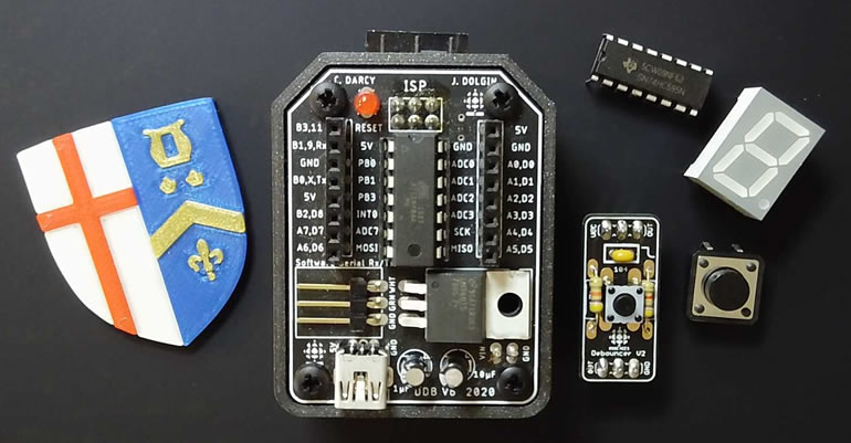
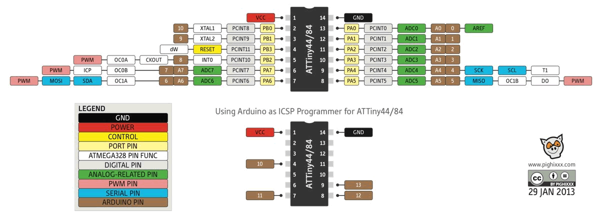
![]() Project 3.4. Pin Change Interrupt. For your first DER project entry employing the Dolgin Development Board v6 in an off-platform application, you are asked to employ the concept of a Pin Change Interrupt to maintain and display a hexadecimal count on a single 7-segment display.
Project 3.4. Pin Change Interrupt. For your first DER project entry employing the Dolgin Development Board v6 in an off-platform application, you are asked to employ the concept of a Pin Change Interrupt to maintain and display a hexadecimal count on a single 7-segment display.
Also introduced in this project is the concept of resuable code in the form of an external library, consisting of ATtiny84/DDB assets this, and future projects, can draw on. This will shorten your development time and make your functioning prototypes more reliable since they'll be based on proven code.
Basic Task.
 Watch this
 Enhanced Task.
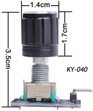
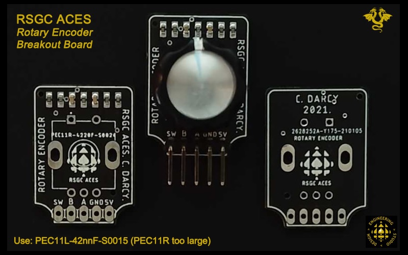
Your Session 5 supplemetary kit contains both the generic KY-040 from Amazon and RSGC ACES' (fully debounced) Rotary Encoder on breakout boards.
Submit your DER and attach the two code files, by the deadline: Saturday January 30.
Note. I encountered an issue with my own counting that I eventually resolved only after walking away from the task for a few hours and thinking about it. It may be instructive to share the problem and the solution. At certain numbers, the count would either skip over the digit or simply stall out. The numbers were typically 2 and, especially, 8. It dawned on these numbers draw more current than other numbers and the MCU/prototype may be choking on the demand. After placing a 1 μF capacitor across the power rails to support the rapid draw, operations were considerably smoother. Replacing the 5V USB power source altogether, with a 9V AC/DC adapter, appeared smooth the issues out completely. Remember this tip should you ever encounter similar current demand spikes in future projects. Here's a short video that monitors the current draw for each if the digits (20 mA/segment) ![]() Current Draw on Counting
Current Draw on Counting
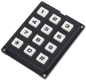
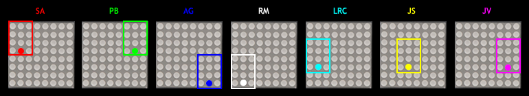
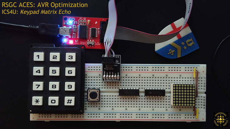
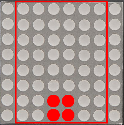
![]() Project 3.3. Keypad Matrix Echo. For your first ATtiny84 project of ICS4U you are to maximize your mid-level coding skills in the development of a prototype that echoes button presses on your 12-key telephone keypad onto your small Adafruit 861 8x8 matrix. Each of you has been assigned a 4x3 subset of your matrix as shown below that represents the 1:1 Key→LED mapping. For example, should your user press the '0' key, the LED indicated will light up for 300 ms, only.
Project 3.3. Keypad Matrix Echo. For your first ATtiny84 project of ICS4U you are to maximize your mid-level coding skills in the development of a prototype that echoes button presses on your 12-key telephone keypad onto your small Adafruit 861 8x8 matrix. Each of you has been assigned a 4x3 subset of your matrix as shown below that represents the 1:1 Key→LED mapping. For example, should your user press the '0' key, the LED indicated will light up for 300 ms, only.
Your ATtiny84 has just enough GPIO pins (10) to pull this task off as I describe it below (7 input; 3 output). Furthermore, the code is surprisingly short if done skilfully.
(Basic) Task.
 Optional (Advanced) Task.
Some of you may wish to consider going beyond the basic task.
Rather than 1:1 Key→LED mapping, a 1:4 Key→LED mapping could be achieved. What is compelling about this implementation is that it requires a skill you already possess: PoV!
You have the time; consider it if you are inspired.
![]() Project 3.2. CHUMP. See here.
Project 3.2. CHUMP. See here.
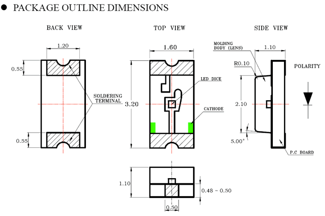
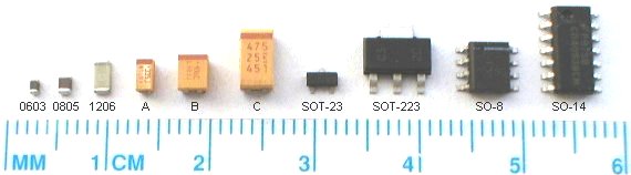
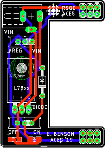
![]() Project 3.1. GB Machine. The greatest challenge (and I believe, privilege) for ACES is to influence the direction of our program. Through your imagination and skill you are expected to contribute to the enhancement of our mutual creativity, tool set, and assets. G. Benson (ACES' 19) fulfilled this opportunity/commitment through his enhancement of the indispensable PB Machine (P. Bagga, ACES '17). Beginning in the Fall of 2019, Sr. ACES are expected to solder up their own GB machine and put it to good use in the pursuit of their own prototypes.. Your experience with electric circuits has been largely limited to components that use through-hole technology (THT). To round out your proficiency with all components, your next few projects will require the use of devices that use surface-mount technology (SMT). As the graphic reveals, the smallest size that is reasonable for hand-soldering techniques is the 1206 family, so this is what we carry in the DES inventory.
Project 3.1. GB Machine. The greatest challenge (and I believe, privilege) for ACES is to influence the direction of our program. Through your imagination and skill you are expected to contribute to the enhancement of our mutual creativity, tool set, and assets. G. Benson (ACES' 19) fulfilled this opportunity/commitment through his enhancement of the indispensable PB Machine (P. Bagga, ACES '17). Beginning in the Fall of 2019, Sr. ACES are expected to solder up their own GB machine and put it to good use in the pursuit of their own prototypes.. Your experience with electric circuits has been largely limited to components that use through-hole technology (THT). To round out your proficiency with all components, your next few projects will require the use of devices that use surface-mount technology (SMT). As the graphic reveals, the smallest size that is reasonable for hand-soldering techniques is the 1206 family, so this is what we carry in the DES inventory.
GB Machine (click image to enlarge) |
1206 LED Package |
|---|---|
 |
 |
Task.
