IR Remote Control. The ultimate goal of this project is to build a universal remote for all the appliances (TVs, DVDs, cameras, etc.) in your home. For starters, see if you can locate an unused remote control clicker for any device you no longer require. They may lying around in drawers, found on the corner on recycling day or simply ask one of your friends if they can spare one.
Step 1. TV Remote Control. You are asked to duplicate of the remote contol used in the lab for manipulating the TV.
TBC...
Step 2. Universal Remote Control. You are required to develop a IR remote control device capable of turning on and off three different electronics devices in your home. Have a family member follow you around the house with a video camera documenting your success.
TBC...
Gravimeter. This purpose of this project is provide the Science Department with a device they can use to demonstrate the principle of acceleration due to gravity to physics students.
Task.
TBC...
Multiple Displays. This purpose of this project is to exploit the Persistence of Vision (POV) principle by performing round-robin updating of three seven-segment displays.
Task.
Using a conveniently-sized breadboard platform, wire an eight pin common bus to serve the anode pins of three FND500 seven-segment displays.
Wire the three ground pins to three separate Arduino pins.
TBC...
Soil Moisture Meter. TBC.
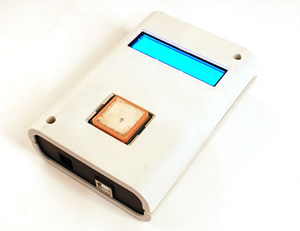
LCD 3. Encasement. Your sensor unit currently consists of your Arduino, an LCD screen, a DHT22 unit, an LDR, a resistor, and some wires. The 5V power is supplied by your laptop. The goal of this stage of the project is to develop a prototype of a standalone unit that displays the results of the data gathering and can be mounted on the Living Wall.
Examine the case you have been provided with more closely and develop a range of options that would result in a standalone sensing system that could be moutned on our Living Wall.
TBC.
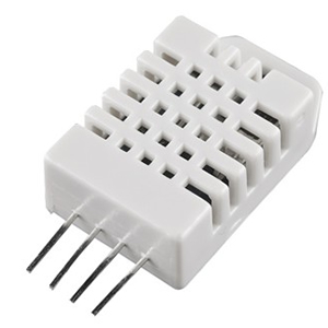
LCD 2.Humidity Sensing & Display. The Living Wall could benefit from an indication of Humidity as well as Temperature and Insolation.
Task.
Review the datasheet for the Digital Humidity Temperature sensor: DHT22 (aka RHT03/AM2302).
Download Adafruit's DHT library and confirm the correct operation of the DHTtester code sample.
Create a new sketch that refreshes the display of the Humidity and Temperature readings from the DHT22 and the Insolation from the LDR (eliminate the use of the LM35DZ) to your LCD at, approximately, 10s intervals.
Be sure to address all comments from earlier ER submissions, prior to submitting this writeup.
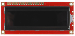
LCD 1.Temperature and Insolation Sensing and Display. For the first installment of your LCD project you will familiarize yourself with the unit you have been provided with and display the temperature (°C) and Insolation.
Open the Arduino IDE and confirm your system by running all the Examples
Obtain temperature (°C) readings using the LM35DZ from your last assignment on A0 and display the labelled result on the first line of the LCD.
The problems with obtaining multiple readings from the Arduino's analog inputs are well documented. Read this Forum Thread to determine the correct strategy.
Use an LDR and 1 MΩ in series as a voltage divider to obtain analog readings from the 'midpoint' to A1 and display the result to the second row of the LCD.
Submit your ER writeup by this Sunday at midnight.
Thermal Management. In this multi-stage project we will explore analog and digital temperature sensing and management. In the process you will make use of your previously created 5V/12V Breadboard-Compatible Voltage Regulator (BCVR).
Step 6. Full Standalone Fan Monitoring.
Place your BCVR into your breadboard so that a 5V potential is available on one power rail and 12V is available on the other. Ensure the ground rails are tied together and served. Do NOT supply power to the BCVR yet.
Connect the VCC and GND pins of your standalone ATmega328P to the 5V and GND rails respectively. DO NOT MISTAKENLY CONNECT YOUR MICROCONTROLLER TO THE 12V RAIL.
Rebuild the circuit from Step 4 around your 328P. This build includes your 12V fan.
Double and triple check your connections. A blown 328P is a real problem.
Connect your AC/DC adapter to your BCVR. Monitor the components for a minute to ensure they remain cool. Disconnect the adapter immediately if there's a problem.
Upload your Step 4 sketch and test your circuit.
In addition to the usual ER sections, include a Fritzing diagram of the complete circuit.
Step 5. Standalone Microcontroller System
A short bit of code called a bootloader must be 'burned' into a blank microcontroller before future sketches can be uploaded. Fortunately this is a one-time operation per unit. The ATmega328P on your UNO has this code loaded before it leaves the factory. Since you have been provided with a completely blank ATmega328P, you must to complete this operation as the first task in this segment.
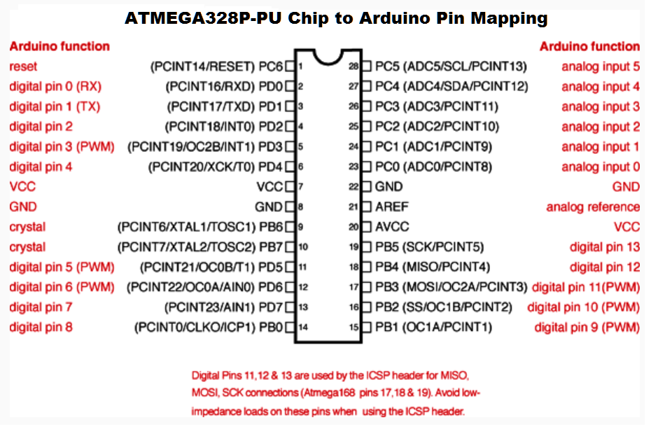
With the bootloader now installed, you can move on uploading sketches to the standalone ATmega328P. Review Part 2 of my Standalone ATmega328P Tutorial and look carefully at the photo. Two issues of note are that the existing ATmega328P is temporarily removed from the Arduino for uploading to the standalone and, in place of the 16MHz crystal and shoulder capacitors, you will use a more convenient, single-unit replacement, known as a Resonator. Confirm you understand the pins that are in use by comparing the photo to the adjacent pin mapping diagram. Wire up the configuration in preparation for your first upload.
The Blink sketch from the Examples>Basic menu of the Arduino IDE is designed to flash an LED on Pin 13. Wire in an LED and 220 Ω resistor, upload the sketch. Debug any problems.
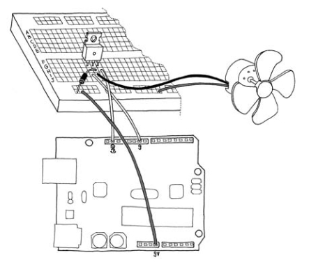
Step 4. Fan Control. With your knowledge of how a MOSFET can be used by the Arduino to drive a higher load you are ready to integrate the past couple of projects into the next stage of our Thermal Management Project. Think hard before you complete the following otherwise you could render one or more components useless.
Gather your Arduino, 5V/12V Breadboard-Compatible Voltage Regulator, IRF520 MOSFET, Nidec Fan and LM35DZ temperature sensor.
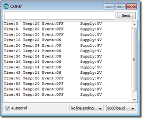
Create the Arduino Project FanControl, and develop a sketch that will use an LM35DZ attached to A0 for input and your DC Fan connected to Pin 9 as one of the two outputs. Your sketch will map the celsius reading over the interval [fanOFFTemp,fanONTemp] to the legal pwm range [0,255]. The pwm value can further map to the voltage range [0,12] (the upper bound is the upper bound of your V+
supply).The other output is your Serial Monitor that will log the activity of your system in the manner depicted to the right.
Now to put it all together. View the short video below that shows all the pieces working together.
Step 3. Digital Temperature Sensing: TMP36 and LM35DZ. Thermistors require a degree of skilful calibration as you found out in the previous stage. Let's move to a component that's somewhat more straightforward. Task.
Using either the Adafruit or Sparkfun resource, create the sketch TMP36 using the code provided and test your circuit using 5V as the default voltage reference. Be sure to display, on one line, the raw reading from the ADC, the equivalent voltage, and the converted temperature in both Celsius and Fahrenheit.
A more precise reading can be obtained by lowering the reference voltage to 3.3V. This is because the 10-bit ADC will produce finer increments. Modify the wiring diagram as described by Adafruit here and adjust the code to reflect new EXTERNAL analogReference (as suggested) and rerun the sketch.
Precision Centigrade Sensor (LM35DZ). The LM35DZ datasheet begins with, "The LM35 series are precision integrated-circuit temperature
sensors, whose output voltage is linearly proportional to the
Celsius (Centigrade) temperature..."
Develop a circuit prototype similar to the circuit presented in the blog.
Create and upload the sketches, solving the debugging issues as you go.
Step 2. Thermistors. A component that changes resistance according to temperature is called a thermistor. They can be positively correlated (PTC or direct) or negatively correlated (NTC or indirect). Using the one you have been provided with, construct a circuit consisting of your thermistor and an appropriately-sized fixed resistor in a voltage divider configuration thay enables you to read the midpoint through A0. Your sketch should report a new line of meaningful data to the Serial Monitor every second that includes as much raw data as possible together with the current temperature in degrees Celsius.
Step 1. Analog-to-Digital Conversion. After reviewing J. Blum's Arduino Tutorial 4 on the Analog Inputs, construct a similar experiment of your own. Be sure to capture media for later inclusion in your ER.
5V/12V Breadboard-Compatible Regulator. It's an appropriate time to put your rapidly-developing EAGLE skills to important use on a project of our own design and implementation.
Many Arduino projects involves using the 5V Arduino platform to drive higher loads, typically of the 12V variety like a cooling fan. To facilitate efficient prototyping an adapter board that would fit onto the end of a breadboard and deliver 5V along one power rail and 12V along the other, with common ground rails, seems like a pretty useful component.
Task.
Sparkfun offers something similar to what I have in mind. Review all the images the page offers to fully understand what their design provides. Kindly, Sparkfun offers the EAGLE files for most of it's boards enabling an even closer look at the designs.
Sketch out a design on a piece of paper. In addition to delivering the input and output supply points and connector types, consider switches, momentary PBs, led indicators, thermal protection, stability points, etc.
Assemble a working prototype of the board to confirm your design.
Using EAGLE, create the schematic. In the board view, consult the breadboard metrics page.
Convert your schematic to a board and measure the size of the breadboard to assist with determining the size of the adapter board.
Connect to breadboard and confirm 12V in one rail and 5V in the other.
Take lots of photos and embed them with your text into a comprehensive writeup that includes Purpose, Reference, Parts List, EAGLE, Procedure, and Media (Photos and Video).
Shift Registers. A number of strategies have been developed for squeezing the maximum performance out of the pins of a microcontroller. One such stategy involves the use of a Shift Register that allows a few pins to control a virtually unlimited number of pins. A common model of shift register is the 74HCT595.
Task.
Review the 74HCT595 datasheet, noting the pinout diagram found on page 4.
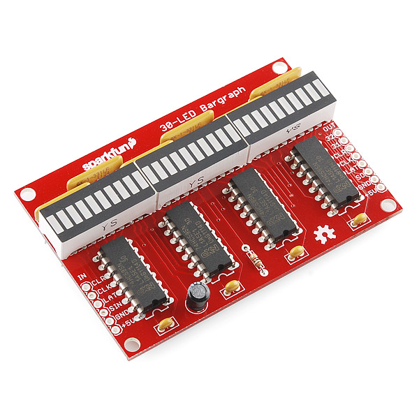
The foundation for our project begins with CIRC-05 from the SparkFun Inventors Guide, found on page 16. Review the description of the project and code. Wire up the circuit, as is, using a bargraph and bussed resistor network for convenience.
Within the sketch you'll notice the use of the statement,
shiftOut(data, clock, MSBFIRST, value);
that results in the 8 bits of each byte shifted into position by positive-going SHCP clock transitions. Review the use of this function here.
Although the loop variable i in the CIRC05 sketch was declared to be of type int, the upper bound of the loop was restricted to 255 to satisfy the Arduino's shiftOut() limitation of the value parameter to a single byte. Shifting larger data values requires segmentation into bytes. Review and be prepared to explain the author's Note half way down the page.
Save the sketch CIRC05 as CIRC05Extended. Using a second set of components (74HC595, bargraph, resistor network), upgrade your circuit and sketch to display the full range of 2-byte unsigned ints (0..65535) to your bargraphs. A YouTube video of one person's attempt appears below.
Include the standard subsections (Purpose, Reference, Parts List, Procedure, Media, Code) in your ER submission.
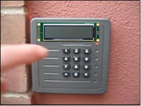
Door Entry System. The goal of this multi-part project is to simulate RSGC's door entry system.
Using the components provided, duplicate the setup as seen in the video in which both the column and row LEDs corresponding to key presses are illuminated.
Develop the Arduino sketch, Entry1, that recognizes when any key is pressed as an external interrupt, and reports the event on the Serial Monitor.
Create the sketch, Entry2, and paste in the Example code at the bottom of the page. Look it over and wire up a prototype, making any edits required to ensure the specific keys pressed are echoed to the Serial monitor.
Add a biColor status LED to the circuit that responds in a manner similar to RSGC's entry status LED. Have the active color display for 100 ms.
Part 3. Entering a Keypad Security Code
Field trip to Chapel entrance to confirm all the features of the functionality of RSGC's keypad security system
Review Project 10 from 30 Arduino Projects for the Evil Genius
Download the code for ALL the sketches in the text from the book's website and unzip them into a folder in your Arduino projects folder
Open the sketch for Project 10 and save it as a new sketch entitled Entry3 in your DoorEntry folder
Look over the code, ensuring you understand every statement and confirm its execution
Modify the code three ways to mimic RSGC's keypad security system:
incorporate the bicolor status LED as you did in Part 2
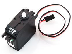
Read CIRC-04 from the Sparkfun Inventor's Guide. Attach (screw) the linear horn to the motor. Load and execute the sketch. Observe the behaviour of the servo.
Modify the sketch to reduce the range of motion of the servo to 0° to 90°.
Integrate the Arduino code from the previous step into your Door (Gate) Entry sketch so that, on the successful entry of the 5-digit secret code, the gate rotates from 0° to 90°, holds for 5s and then rotates back to 0°.
Part 5. Controlling the Latch (Solenoid)
For the final segment you are asked to integrate a locking mechanism for your gate in the form of a 5V solenoid switch.
Since this component is based on an inductive coil that draws considerable amperage (1A) your Arduino employs a low-side transistor to draw current for the solenoid from a separate power source. The two voltages are share a common ground on the Arduino.
Your solenoid should turn on when the user submits the correct code, prior to opening the gate. After 5s the servo returns the gate to it's original position and the solenoid is turned off.
This the final ER submission before the holidays and it is substantial. Be sure to organize and title your sections clearly, include all relevant data, explanations and visual support.
Measuring the RPM of a DC Motor. This project takes both an analog and digital approach to measuring the rotations per minute (RPM) of a typical DC hobby motor. In the process begin the first of many projects that require a degree of model building.
Task 1. Analog.
Fashion a device that be used to connect your DC motor and worm-gear driven analog counter via a rubber belt.
Setting your supply voltage to 2V, record the time taken to overflow the counter 5 times.
Develop an Excel worksheet that records this data, together with the results of your peers, to arrive at at estimate for the RPM of your DC motors.
Intermediate Task. External Interrupt Service.
Based on last week's discussion surrounding the concept of an external interrupt, assemble a working prototype that uses the sample code to 'respond' to a button being pressed or released. Report the state of the LED to the Serial monitor as necessary.
Comment on any inexplicable behaviour you observed.
Adapt the code so that an LED turns on with the press, and off with the release.
Task 2. Digital.
You have been introduced to the SHARP GP1A57HR PhotoInterrupter. and the Arduino's ability to service external interrupt requests. Configure a prototype system that triggers an interrupt on each rotation of the wheel attached to your DC Gear Motor operating at 2V. The adjacent breadboard image can be used as a guide.
Develop an Arduino sketch that counts the number of interrupts over a 60 s period and displays the count to the Serial Monitor every 10s.
Add your data to the RPMAnalysis workbook and draw comparisons between the Analog and Digital experiments and state conclusions.
Develop your ER summary and submit by the deadline. Be sure to include reference to the resources employed in both expermients.
Faux Fire Effect. The primary purpose of this project is to introduce you to the Arduino's ability to mimic analog behaviour through a technique known as Pulse Width Modulation. To demonstrate the technique you will undertake a simulation of a flame (just in time for Hallowe'en!)
Check out this video from a 2012 RSGC ACE of his response to the project
Create, enter, and modify the sketch provided from Earthshine using the supplied LEDs (or ones purchased on our field trip later today!)
Your goal is to produce a realistic flame effect. To complete the illusion you'll need to acquire a diffused container that you can place over the LEDs as in the photo above.
Obtain and upload a video of your flame and supply a link with your ER summary. Here's an effort from another RSGC ACE...
Alphanumeric Display. Seven-segment LED displays are designed to represent a single decimal digit (0-9). To display alphabetic characters as well, the 17-segment alphanumeric display was developed. You will familiarize yourself with this device in this activity.
Task A. Getting to Know the Component
You have been provided with a 17-segment display. Examine the labelling on the side of the device and, using your internet search skills, locate the datasheet (obtain a hard copy and hang onto to it tightly).
From the datasheet, identify the electrical characteristics of the package before probing the pins by number to determine the respective segments they map to. Create a Word table that summarizes the pin-to-segment mapping. This table will find its way into your ER.
Edit your ER under the entry indicated above, with sections that include, Purpose, Reference, Pin/Segment Map and Media.
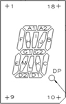
16-Segment Alphanumeric Display
Pin Segment Map
The small breadboard that comes with your kit is not sufficiently large enough for this exercise. Using a triple-sized breadboard place the display device so that it straddles the valley on the middle board.
After selecting a power source together with wires and an appropriately-sized resistor, confirm the performance of each of the 17 LEDs.
Place appropriately-sized fixed resistors outwards from the pins of the display so that they fall onto the outer breadboards.
Run hookup wires of sufficient length from the resistors to the pins on your Arduino according to your understanding of the mapping.
Task B. The Sketch.
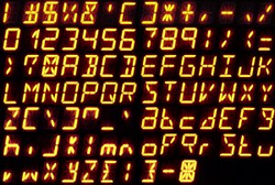
The purpose of the sketch for this project is to have the Arduino display the 10 decimal digits followed by the upper- and lowercase letters, continuously, with a short delay between each character.
This blog provides arrays for both the uppercase letters and the decimal digts that you are free to copy. Using the graphic above right, develop your own map for the lowercase letters.
Develop and test your Arduino sketch.
Obtain a video of your working system, upload it to your video channel, and provide a link to it from your ER.
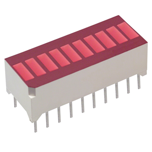
Project 1. LED Bargraph. It would make sense to start the submission side of this course where TEL3M left off.
Using the LED Bargraph and resistor network you've been given together with additional parts from the kit, breadboard a prototype circuit that uses 10 of Arduino's digital output pins to run the LED sequence indefinitely.
Create a new Arduino sketch, LEDBargraph, that executes the sequence. Do NOT copy, paste, edit an existing sample sketch, you won't learn as much. TRy to do it from memory, referring back only when you're stuck!
Ensure the code is as tight as possible and carry over as many good code design techniques as possible from your Java Robots experience with from last year.
Document your code fully.
Insert a new full page in your ER with TEI3M: Computer Engineering Technology, Emphasis: Interfacing
Add a new Activity entitled LED Bargraph and include the Sections: Purpose, Parts List, Procedure, Media, and Conclusion. The Parts List section should include the following column headings: Part, Quantity, Details and Datasheet. Datasheets (pdf version) are available online. Search online (identify by name or find a part number on the component) and download the datasheets prior to uploading them to the Web Publishing folder of your First Class account. A link to the respective datasheet (.pdf) is required for each of the additional parts you are given in each project. The Media section should offer well-chosen, 250px wide photos and images. Don't be afraid to create and maintain either public or unlisted video logs of your projects this year. They'll come in handy for future job interviews.
Finally, you will remember from last year I reward creativity, insight, and imagination as well as evidence of your technical skills with hardware, software and applications such as Word, photo and video editing.

 IR Remote Control. The ultimate goal of this project is to build a universal remote for all the appliances (TVs, DVDs, cameras, etc.) in your home. For starters, see if you can locate an unused remote control clicker for any device you no longer require. They may lying around in drawers, found on the corner on recycling day or simply ask one of your friends if they can spare one.
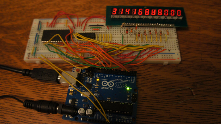
 Step 4. Fan Control. With your knowledge of how a MOSFET can be used by the Arduino to drive a higher load you are ready to integrate the past couple of projects into the next stage of our Thermal Management Project. Think hard before you complete the following otherwise you could render one or more components useless.
 Step 3. Digital Temperature Sensing: TMP36 and LM35DZ. Thermistors require a degree of skilful calibration as you found out in the previous stage. Let's move to a component that's somewhat more straightforward. Task.
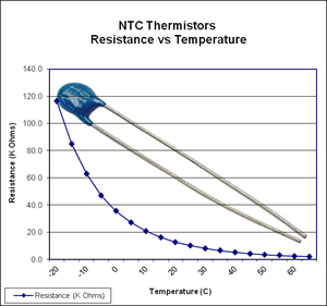 Step 2. Thermistors. A component that changes resistance according to temperature is called a thermistor. They can be positively correlated (PTC or direct) or negatively correlated (NTC or indirect). Using the one you have been provided with, construct a circuit consisting of your thermistor and an appropriately-sized fixed resistor in a voltage divider configuration thay enables you to read the midpoint through A0. Your sketch should report a new line of meaningful data to the Serial Monitor every second that includes as much raw data as possible together with the current temperature in degrees Celsius.
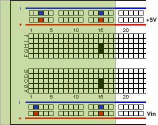
 Change the password and retest
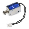
 Task 2. Digital.
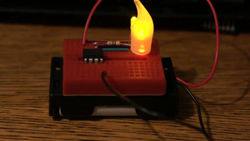
 Faux Fire Effect. The primary purpose of this project is to introduce you to the Arduino's ability to mimic analog behaviour through a technique known as Pulse Width Modulation. To demonstrate the technique you will undertake a simulation of a flame (just in time for Hallowe'en!)
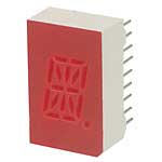
 The small breadboard that comes with your kit is not sufficiently large enough for this exercise. Using a triple-sized breadboard place the display device so that it straddles the valley on the middle board.
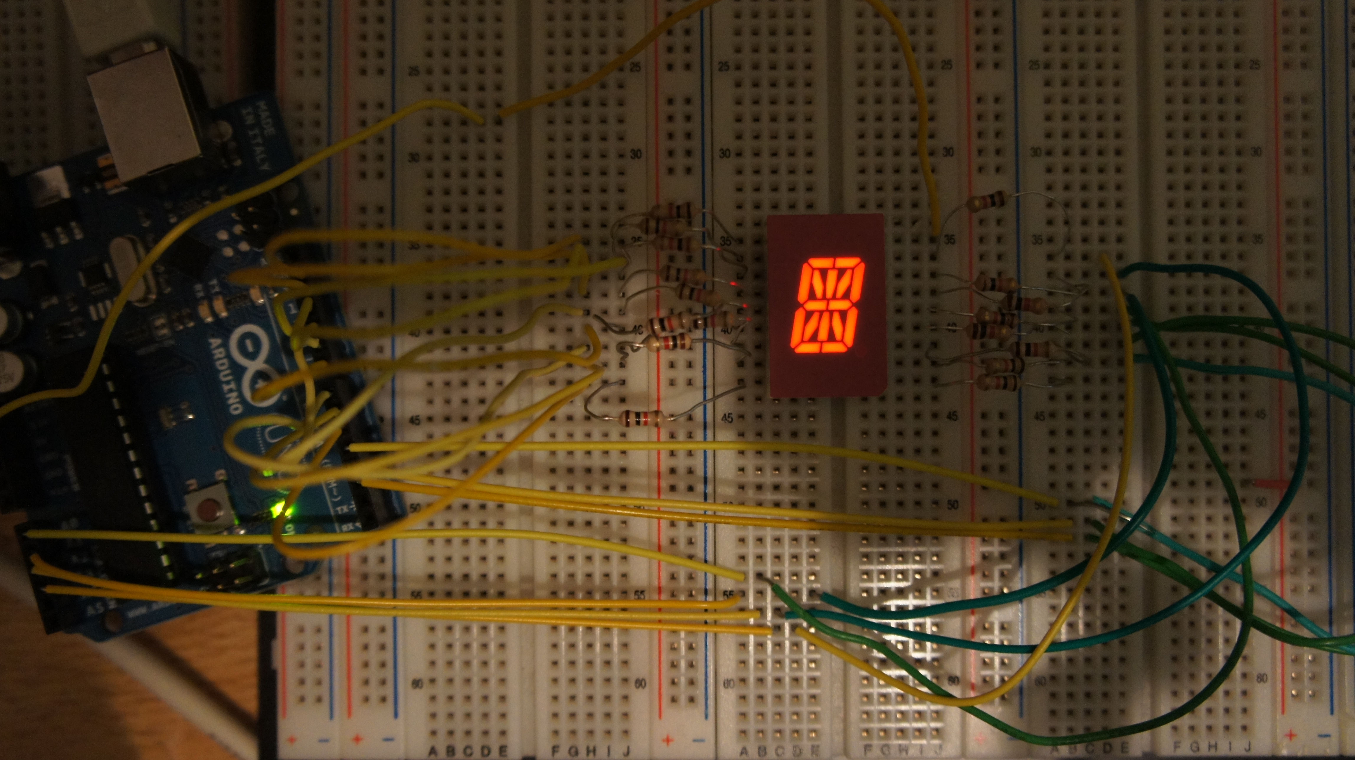