Project 4. A Counting Circuit
Every one of us can tell the difference between quality and junk in a heartbeat. As a young scholar you have to decide what your name will stand for. I believe it should matter very little whether you enjoy a task or not; if you're going to attach your name to something it is a direct reflection of who you are.
This final activity introduced a simple introduction to fundamental capabilities of many digital devices: counting and display. There were a number of stages or subcircuits in this system and your ER will clearly present the role played by each.
A comprehensive report for this exercise is a significant undertaking in which students, for whom marks are important will use, the full 70-minute period alotted to you as well as a portion of their Christmas Break.
Start your ER with a big picture Theory section,
written in your own words that mentions, generally, the input to the system, the generation of a clock signal consisting of pules having both a duration and a frequency, culminating in the presentation of the pulse count on the display device. This would an ideal place to present a detailed, margin-to-margin Fritzing diagram, breadboard or (organized) schematic view, to introduce your readers to the full prototype you are about to describe and discuss in three pages that follow.
A Note on Graphics. Graphics should support the text they are illuminating. Poorly composed photos, sloppy and inconstent choices for diagrams like pinouts and schematics work against you as they can confuse your readers and leave them with a sesne that the author doesn't care about his presentation so why should they?
Follow the Theory Section with the six subsections described below. For the first section, Analog Input, include, as a graphic, that part of the schematic that it pertains to. The latter five subsection should start with their own Reference Section that include the respective live hyperlink appearing below for your convenience:
Following the Reference subsection within each of the five areas, include a Purpose section
describing in detail, how each stage contributes to the sequence. Be sure to clearly present the input, processing, and output of each stage, supported by informative, attractive, and well-formatted graphics.
Following the final subsection include Media (captioned photos and video) and Conclusion sections.
A. Analog Input
- Purpose (discuss the PBNO switch and the pullup resistor configuration)
- Include your own breadboard/schematic diagram, right-aligned, to
support your discussion.
B. NAND Gate Oscillator (4011)
- Purpose
- Explain, in detail, the function of this chip (Input, Processor, Output)
- Explain the concept of analog input to digital output and how this
chip accomplished this
- Include
a discussion of the pin diagram in this
IC
- Explain what a clock signal is
- Discuss the role played by RC1 and RC2 and the role played by its respective capacitors and resistors.
- Pinout diagram taken from the web and your own breadboard /schematic of the wiring and supportive analog components
C. Decade Counter (4017)
- Purpose
- Explain, in detail, the function of this chip (Input, Processor, Output)
- Explain what it means to ensure ALL of the input pins must be conditioned and
how this is done
- Pinout diagram taken from the web and your own breadboard /schematic of the wiring.
D. Decimal Counting Binary Up/Down Counter (4510)
- Purpose
- Explain, in detail, the function of this chip (Input, Processor, Output)
- Create a two-column table with rows for all 16 4-bit binary values in the
left column and their equivalent decimal values in the right column
- Pinout diagram taken from the web
E. Binary Counting Decimal Decoder (4511)
- Purpose
- Explain, in detail, the function of this chip (Input, Processor, Output)
- Explain the purpose of the Blank, Store, and LampTest pins and how they must
be conditioned for normal use.
- Pinout diagram taken from the web
F. Seven-Segment Display
- Purpose
- Explain, in detail, the function of this component
- Explain the difference between the Common Anode (CA) and Common Cathode (CC)
versions of this component. Which one did we use?
- Explain how the pins on the 4511 and 7-seven semgent make the wiring straightforward.
- Explain why each pin on the display requires its own resistor.
- Graphic (google a similar small image)
- Pinout diagram taken from the web
Be sure to address ALL issues from previous submissions and update your Table of Contents before attaching ER.docx to an email to handin under the Subject Line: A Counting System
Project ?. The Basic Digital Logic Gates
For this weekend's submission you are asked to,
- Insert the Word document, Inside Gates, into your ER after Project 4, retaining the landscape orientation of the document. Complete the truth tables and insert your Fritzing schematic images representing the appropriate transistor configuration underlying each gate. Finally, adjust the table shading to be consistent with your ongoing theme.
- Complete the Exercise: Integrated Circuits, CMOS ICs, found on page 75. Using your 'highly-developed' hanging indent skills, retype the questions and provide your answers for the 13 questions.
In this activity, you are asked to seamlessly incorporate the completed Inside
Gates worksheet
into your ER.
Be sure to update your Table of Contents prior to submission.
Appendix A. Tables and Exercises
The Binary Number System
Within Appendix A. Tables and
Exercises and under the subheading
The Binary Number System (in Heading 3 style) enter the questions below and supply
your answers.
- In your own words, what is the ASCII
Table and explain its purpose. Provide a link to this web site in
your ER.
- In your own words, what is Unicode and
explain why it was required. Provide a link to this web site in your ER.
- What is your surname in binary? Present your answer in a well-formatted
table.
- Translate the encoded message below into English with
the
help of the ASCII Table.
Use a well-organized and formatted table to present your results.

Here is the code in text form if you would
find
it useful. A word of advice: You could
convert the binary codes directly to decimal (Base 10) and then look them
up in the ASCII table, but you may find it easier to convert the
binary numbers
to their hexadecimal (Base 16) equivalent, and use these values to determine
the character. Not to mention the benefit of further experience with the
important hexadecimal number system.
- Question 2 on page 66.
- Question 3 on page 66.
- Question 4 on page 66.
Do not forget to update your TOC. Submit
your ER as an attachment to an email to handin with the Subject: The Binary Number System
Project ?. Professional Style Alarm System
 Your writeup for this activity will include,
- Graphic of Figure
L12-7 (adjacent).
- Digital photos of the front and back of your working, soldered PCB.
- Provide a link to Figure
L12-7, the animated alarm.
- Type in the Exercise questions 1-8 from page 45 and merge in these
answers using your (pro) formatting skills. You are responsible
for understanding these supplied answers as they may be part of the future
assessments.
- Update your TOC.
Submit
your ER as
an attachment to an email to handin with the Subject: Professional Style Alarm System
Appendix B: Quizzes and Tests
Analog Review
- Insert the file Quiz3.docx into
your ER, starting on a new page following your previous Resistors quiz.
- Adapt the formatting as well as the headers and footers, to your current
ER style.
- Provide complete and accurate answers.
- Update your TOC.
- There is no need for a separate submission of this effort since Activity
4 is also due today (Saturday November 27).
Project ?. The Automatic Night Light
Your writeup for this Activity will include,
- Purpose, Reference and Procedure subsections (Heading 3 Style) with appropriate content.
- Fritzing schematic view of Figure L12-1 (right).
- Fritzing breadboard view of Figure L12-1.
- Clear photos of front and back of your soldered PCB
- Questions and your full sentence, hanging indent-laden, responses to
#'s 2, 3, 6, 7, 9, and 10 on pp. 44-47.
- (Optional) A video of the complete circuit development process and result.
Address, but do not remove, the concerns expressed
in ALL my comments embedded in your ER.docx from last submission.
Submit your ER.docx as
an attachment to an email to handin with the Subject Line: The Automatic Night Light
Project ?. The NPN Transistor
This is a major assignment.
If you use
class time wisely
to gather the necessary
data
and develop a quality submission you will be rewarded.
 Turn to page 33 and review the Exercise
based on Lesson 9. You are asked to complete this exercise as described below.
Turn to page 33 and review the Exercise
based on Lesson 9. You are asked to complete this exercise as described below.
- Starting on a new page, immediately following Project 3, include the title Project 3. The
NPN Transistor, in Heading 1 Style.
- Add the subtitle, Exercise:
Introducing Transistors in Heading 3 Style as usual.
- Insert 2 consecutive Continuous Section Breaks.
- Position the cursor between the Continuous Section Breaks and define
a 2-column format.
- Turn off Auto-Numbering.
- Insert the unformatted
questions.
- Format the questions using your hanging indent skills and supply your best,
concise formatted answers to each.
- Insert a Column Break(s) at the most strategic location(s)
to avoid orphans (a question in one place and its answer in another)
- Strategically insert your own Fritzing Schematic and Breadboard views of this Project between questions. Remember, we've modified the circuit presented in the text.
- Embed a closeup digital photo (250px wide, 1px black border) of your NPN Transistor circuit clearly showing the parts and their
connections
- Update your TOC.
After ensuring all corrections
have been addressed from your previous submission (without removing
my comments) and with Headers and Footers in place, submit your ER.docx as
an attachment to an email to handin with the Subject Line: The NPN Transistor,
by the deadline.
ER Resubmission (Optional for most). All students should address
their ER comments.
- Those students who have EVER missed
a week's submission MUST complete the assignment and resubmit
this Saturday.
- All students are invited to resubmit their corrected ERs this
Saturday for increased credit once ALL corrections have been made.
- Those students who
received
less
than 8/10 for last week's submission would be foolish not to resubmit.
Appendix B. Quizzes and Tests
To ensure your Engineering Report is as complete a study guide as possible
in preparation for the final evaluation in late January, you will insert
all the CORRECTED
quizzes and tests administered in the course into your ER.
Task.
- Insert a page break after Appendix A. Tables and Exercises
- Add the text, Appendix B. Quizzes and Tests in Heading
1 style
- Add the text, Quiz 1. Greek Alphabet in Heading 3 style
- Add a blank paragraph and then Insert Quiz1GreekAlphabet.docx,
removing the existing title that appears in Heading 1 style
- Adjust other formatting details as required
- Complete the missing entries in the table
- At the end of the table, insert a Next Page Section Break
- Switch to Landscape orientation (Page Layout menu)
- Add the text, Quiz 2. Resistors in Heading 3
style
- Add a blank paragrpah and then insert Quiz2Resistors.docx,
adjusting rulers, margins, etc. as necessary to remain consistent with the
rest of your Engineering
Report.
- Add the correct answers
- At the end of the quiz, insert a Next Page Section Break and switch back
to Portait orientation
Appendix A. Tables and Exercises
In addition to formal Activity writeups, you will be asked
to add a table of results to your Engineering Report. These tables will be
added to Appendix A that follows your Activity section.
Task.
- You are to duplicate the formatting of Table L5-1 as closely as possible
- Insert a page break after Activity 1. Measuring Voltage.
- Add the text Appendix A. Tables and Exercises in Heading
1 Style
- Add the text Table L5-1 in Heading 3 style
- Add the 8 by 5 table from page 18, centered on the page.
- Add the measurement data, center-aligned within each cell.
- Add borders and alternate background shading that will remain consistent throughout ALL your future ER tables.
Project ?. Digital (Transistor-Based) Logic Gates
 For this submission you are asked to,
 Merge the Word document, InsideGates, into your ER on the first page after Project 3, retaining the landscape orientation of the document. Be sure to format all the requirements below into this single page, scaling as necessary, but retaining maximum readability.
- Ensure your ER header and footer elements run through the page, adjusting the tab stops as necessary to accommodate landscape orientation.
- Set the title to your Heading Style.
- Adjust the cell shading to be consistent with your previous preference.
- Complete the Fritzing Schematic Name, Symbol, and Truth Table for each of the remaining three transistor-based gates. Do NOT make any mistakes; it's too important!
- Be sure to update your Table of Contents prior to submission.
Project 3. The 3D Christmas Tree
 Under appropriate Heading 2-styled subheadings (Reference, Purpose, Procedure, Media and Conclusion) your ER submission for this Project
will include the following.
Under appropriate Heading 2-styled subheadings (Reference, Purpose, Procedure, Media and Conclusion) your ER submission for this Project
will include the following.
- In your Report you will reference your previous project, the Analog Oscillator, and the specific role it plays in the circuit. Your description will be supported by an image of the schematic of the circuit (below). Since it
is quite wide, you should center-align the graphic on the page.
- A paragraph describing your kit (include a full Parts Table, right-aligned within the Procedure Section, consistent with your previous table formats and my previous email Feedback comments)
- Photos of your 3D Christmas Tree accompanied by a link to a video of your tree in action, ideally within a seasonal context. Use some 'nativity creativity'.
- Update your ToC.
Attach your ER to an email to
handin with the Subject: The 3D Christmas Tree by
the requested deadine.
Project ?. The Automatic Night Light
 This is a major project in that after a successful prototype build on your breadboard you will assemble a permanent version by soldering the components to the custom printed circuit board in your kit. After that, you will mount the unit in some form of permanent housing. Since you will be submitting a full ER entry for this project, you will document the build process with photos and video as it evolves. (Another objective of this project is to start you thinking about your personal ISP project that will require you to research/envision a circuit to build, assemble, and present)
Prototype.
- Be patient and assemble a quality prototype of Circuit 4.1. Take a high detail photo for your ER Summary.
- Consider the Test Point shown in Red below. With a DMM, obtain and record voltage readings for the various settings described below.
- Set the pot to 0 Ω (wiper C all the way to A) and under fairly good light, measure and record the voltage at the Test Point.
- Now, obscure the LDR completely with a heavy dark covering and take another voltage reading. Explain the difference.
- Adjust your pot to 50k Ω (wiper C halfway between A and B) and repeat the previous two measurements. Record and discuss the results.
- Finally, set your pot to its full 100k Ω setting (wiper C all the way to B), and repeat the two measurements one last time. Record and explain your results.

ER. Your writeup for this Project will include,
- Purpose, Reference, Procedure, Media and Conclusion subsections (Heading 3 Style) with appropriate content.
- Include a background-shaded Parts List Table, right-aligned within your Procedure subsection.
- Incorporate the measurements taken earlier with your prototype into a response to Question 1 on page 38 of our Workbook.
- Fritzing schematic view of Circuit 4.1. You may use the one below as long as it is properly sized.
- Clear photos of front and back of your soldered PCB.
- Photos and a video of the complete circuit development process and result in action.
Address, but do not remove, the concerns expressed
in ALL my comments embedded in your ER.docx from the last submission.
Submit your ER.docx as
an attachment to an email to handin with the Subject Line: The Automatic Night Light
Project 2. Analog Oscillator
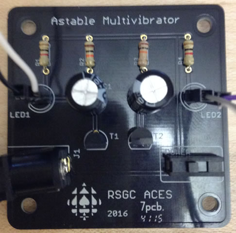
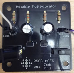 Cole Norton (RSGC '14), prepared and delivered a workshop for interested Georgians in his graduation year on a recreational application of an analog oscillator that could be used to create blinking eyes in a Halloween pumpkin. Cole's legacy of having ACES 'pimp their pumpkins' each Halloween has been kept alive the point that you now have a customized printed circuit board (right) to support this useful activity.
Task.
- Clean the lens of your phone's camera, as you will be gathering media (photos and videos) throughout this project, from start to finish, in support of your ER project summary due Saturday November 4.
- This project will test your organizational abilities as much as your nascent electronics' knowledge and skills. You have been supplied with a bag containing the necessary parts to prototype this circuit. Part of the task includes thinking deeply about what you're doing. In support of this aim please be aware that replacement parts will not be supplied by me.
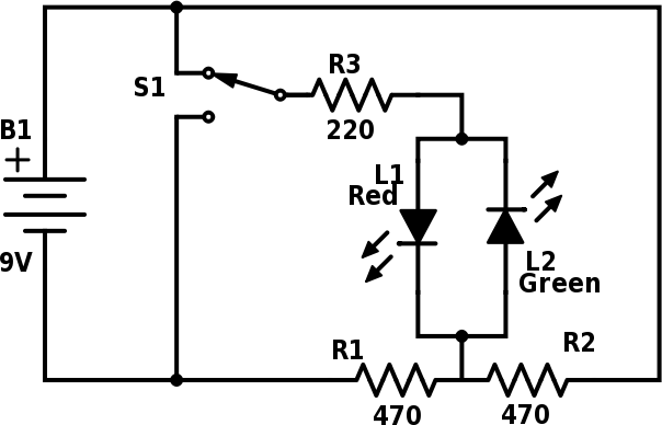
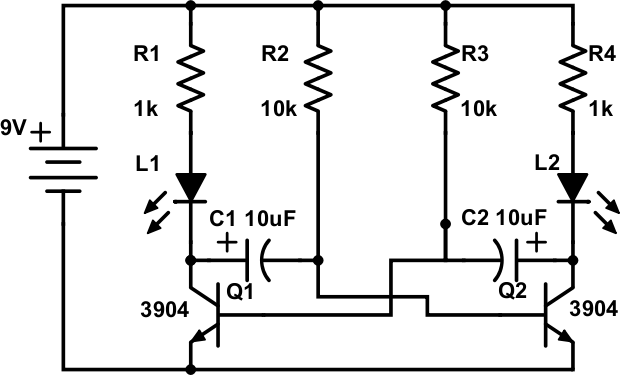
- After studying the schematic of this oscillator circuit below (also found on page 37 of our workbook), and reviewing the parts in the distributed kit, undertake your prototype of the analog oscillator (aka, blinker, Astable Multivibrator) on your breadboard. When you are confident the circuit has a chance of functioning, apply 9V power. Debug as necessary and document the results with your phone's camera.
You may wish to experiment with the rate at which the LEDs are flashing by adjusting the sizes of the resistors.
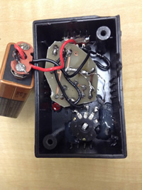
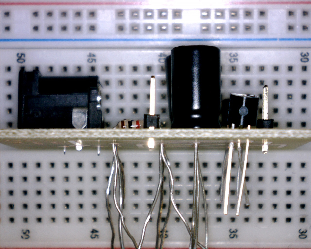
- Once you have obtained your media, you can request the additional parts that include a printed circuit board (PCB), a DC power jack, two pairs of male header pins, two 7" paired wires and a pair of 10mm orange LEDs. Disassemble your prototype and 'dry fit' the parts on your PCB (above right) in a manner similar to the image to the right (click to enlarge). This is an important step to appreciate the full scope of the task that lies ahead and to avoid the risk of soldering parts incorrectly that can be difficult, or near imposssible, to repair.
- With your soldering area fully equipped with easy access to the required tools and conscious of the soldering techniques and strategies discussed in class and in this soldering video, you may begin the soldering stage. Remember,
- Never solder with the power plugged in.
- Your soldering station should be kept no higher than 300°C.
- Keep the parts as tight to the surface of the PCB as possible. The reverse tweezers can help with this.
- The soldering tip should be clean and tinned.
- Any longer than 4s with the soldering tip on the leg of a component runs the risk of damaging the parts!
- Solder the smaller components first: resistors, then transistors, then pin headers, then DC jack, and finally the capacitors.
- On multi-legged semiconductors, it is good practice to solder one leg, solder another part, then return to the original part. This practice minimizes the cumulative heat effect on parts.
- If you have invested care and thought into your efforts, plugging your 9V adapter into the DC Power Jack should yield the desire outcome: a pair of blinking lights. If it doesn't function as expected, prepare yoursefl for the best part: debugging. Seriously, nothing is as rewarding that analyzing and repairing a faulty system. Use the large illuminated magnifying glass to check all your solder joints. Confirm your polarized parts are in the correct way. Use the DMM to to perform continuity, voltage, and integrity inspections. You'll find the problem without the need to ask my opinion.
- Before you leave for home on October 31, you are to demsntrate your working oscillator for me and I will initial your board as a sign that it is functioning. You will install your oscillator in your pumpkin on Halloween and obtain some video of it working that evening. Interviewing kids coming to your door trick or treating and asking them what they think of your blinking pumpkin will earn extra credit.
- ER. Starting on a new page, add the Project name and complete sections under the subheading: Reference, Purpose, Theory, Procedure, Media, and Conclusion. Text is developed in accordance with the recommendations for Technical Writing and reflective your strong formatting abilities. Graphic manipulation is undertaken according to the specifications laid out in the Engineering Report General Guidelines.
- Attach your ER to an email to handin with the Subject: Analog Oscillator by the deadline.
Project 1. Voltage Dividers
 One of the most important skills an Engineer must possess is the ability to communicate, both in spoken word and in written form. Developing this skill takes much practice and this is precisely why the Engineering Report plays such a crucial role in our program (and your mark!)
For your first Engineering Report (ER) submission, you are to present an adaptation of the Voltage Dividers circuit described in class on Friday September 29. As you recall, this circuit was a modification of the circuit to the right that appears on page 11 of our workbook. You are required to be familiar with the Guide for Technical Writing and through practice and regular editing your sentence structure will improve. Poor grammar and spelling skills detract from your presentation.
Task.
- Create the Word document, ER.docx that includes the title page, Table of Contents and headers and footers as discussed in class.
- Each Project writeup starts on a new page.
- For this project subsections must include Reference (Include a hyperlink containing the URL of this project description), Theory (include a discussion and purpose of a voltage divider), Procedure (discuss the two (fixed and variable) voltage dividers used in this project and prototyping sequence), Media and Conclusion.
- Include a complete Parts Table, right-aligned within the Procedure Section.
- Technical writing is not presented in the first or second person. Text should employ either the active or passive voice.
- Develop your own Fritzing breadboard and schematic images for inclusion in your submission and store them in your images folder. Include them in a Media subsection together with high resolution, well-composed, and formatted photos.
- Create a short (~1 min) video of your circuit with accompanying explanations and annotations of the components. Upload to YouTube and include a link in the Media section. Review some of the best student videos on our ACES' home page to get an idea of what is expected.
- Provide a Conclusion. A single, well thought out paragraph is appropriate and should be written in the first person. See page 70 for two good examples.
- Update your Table of Contents.
- Attach your Engineering Report (ER.docx) to an
email to handin with the Subject: Voltage Dividers by
the required due date.
Remember, your text should be developed in accordance with the recommendations for Technical Writing.
Project 1. Modifying the 9V Adapter
 You are ALL potential engineers. You must believe in yourself. For this first project, and all others to follow, please keep in mind that the quality of your work is a reflection of the respect you hold for yourself. High quality results are achievable by anyone willing to demonstrate passion and patience in their work.
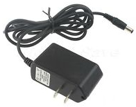
A Regulated 9V AC DC adapter is better suited to our prototyping activities than 9V batteries. Disposal of the latter is problematic and battery clips snap with frustrating regularity (there's a reason they give you a half-dozen of them).
Task.
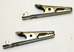 Alligator clips offer a better interface with the breadboard than the barrel jack. Using the cutting jaw of the Wire Strippers, cut cleanly through the cord, roughly 5 cm from the jack and give the end to Mr. D. These components can be reused in future projects.
- Following more detailed instructions provided in class, strip the sheathing from the power cord a further 4 cm and remove the sheathing from the red and black supply leads, 2 cm from their ends.
- Remove the red and black soft plastic covers from the alligator clips and slip them on the red and black leads, respectively.
- In addition, slip a half-length (1.5 cm) of heat-shrink tubing over each of the read and black leads.
- For each lead, slide the exposed copper through the hole in the clip and loop it around again to the jaw of the clip making sure it maintains good contact with the metal clip. Using a pair of needle-nose pliers, crimp each wing of the jaw over the wire, one at a time.
- Slide the heat-shrink tubing over the joint and, using the heat gun, shrink the tube to strengthen to the joint.
- Slide the soft plastic covers over the clip and test.
Engineering Report
Employing the best practices discussed in MIT's Technical Writing document, follow the instructions below to complete the
first entry in your Engineering
Report.
- Organization is a key to success. Create an appropriately-named folder on your laptop (i.e. Circuits, TEL3M, Hardware)
to house the files related to this course. Within this folder create a subfolder entitled images that will house all the photos and graphics you will create in this course.
- Within this folder, create a Word document entitled ER.docx.
- Follow the instructions provided in class for creating a title page, Table of Contents, and Project 1 page.
- For Project 1, include
the subsections: Title, Reference, Purpose, Procedure and Summary.
- Complete the text of each section, written in Active voice, embedding right-aligned photos that you took to document the development of the project.
- Finally, never forget to update your Table of Contents as the final action prior to submission.
- Attach your Engineering Report to an
email to handin with the Subject: Modifying the 9V Adapter by
the required due date.
Project 0. Lemon Power
Before you begin your year, you should
decide what your approach will be.
Are you a minimalist, whipping the
work off as fast as you can to simply 'get it over with' ?
Or, at the other extreme, are you prone to rambling on in
the hope that the
teacher will eventually find everything anyone
could possibly include on a topic?
My recommendation lies in the middle. Think
deeply and write economically.
A succinct,
well-conceived response will maintain your readers' attention while still
garnering the credit you're hoping for.
 Section
A. To get the juices flowing so to speak, you are asked to explore
the ability of a few simple household items, in combination, to generate
electricity. Undertake the steps outlined below and records your answers
and measurements.
Section
A. To get the juices flowing so to speak, you are asked to explore
the ability of a few simple household items, in combination, to generate
electricity. Undertake the steps outlined below and records your answers
and measurements.
- Without resorting to any form of research, what is your simplest, straightforward
explanation for the concept of electricity?
- Research the basic construction of a dry cell battery (e.g 1.5V AAA, AA,
C, D) and, in your own words, include a simple, straightforward explanation
how this kind of battery works.
- What are the two fundamental units used to quantify electricity in a circuit.
 Section
B. Despite the fact that the amount of electricity we
use in this course to power our circuits is small, it is important that it be
deployed in precise
amounts. The tool we'll use to monitor the electricity is called a Digital
Multi meter,
or DMM for short.
These are relatively expensive devices so please handle them with care.
Section
B. Despite the fact that the amount of electricity we
use in this course to power our circuits is small, it is important that it be
deployed in precise
amounts. The tool we'll use to monitor the electricity is called a Digital
Multi meter,
or DMM for short.
These are relatively expensive devices so please handle them with care.
- Turn on the DMM, position the center dial to Volts, V, and toggle the FUNC
button so DC appears on the LCD screen.
Section C. The parts you have at your disposal
include a lemon, a galvanized screw, a copper penny, two alligator clip wires,
an LED and a DMM.
- Google an image of the electron shell for Zinc. How many electrons inhabit
its outer shell? Do the same for Copper.
- Why might these observations make these elements well-suited for the promotion
of electricity?
- Explain how inserting a galvanized metal screw and a copper penny in a lemon
mimics the construction of a dry cell battery.
- Using your alligator clips and DDM probe, measure and record the voltage
of your lemon battery.
Section D. Presumably the purpose of understanding electricity
is so that we can put it to work. Typically this involves assembling a sequence
of
components that convert electricity into useful output. Each of you have been
given the same type of LED.
- Your LED is a useful device. It converts electricity into visible light.
Remembering our discussion of the design of an LED, connect it to your lemon
battery and record your observation of its behaviour.
- Is the output of your LED any different from the other students'?
- Explain how you could work with a partner to improve the output of the LED.
 Activity
13. Flashing
Bicycle Light
Activity
13. Flashing
Bicycle Light
By varying the values of the external capacitor and two resistors,
the output of the 555
Timer IC at pin 3 can be made to pulse with different
frequencies. This IC will be the heart of our third and final project: the 40-LED
Bicycle Light. The parts kit for this project is relatively expensive.
You are asked to produce a final project that reflects a high quality of
assembly.
Tuesday May 13: The 555 Timer- Frequency and Duty Cycle
 An oscillator is a circuit that outputs a voltage waveform. Back
in late January, we examined one such circuit based on the NAND
gate that
used an RC circuit to assist in producing a digital waveform consisting of
alternating HI-LO-HI... voltage levels on PIN 3 of the NAND Chip.
The 555
Timer IC packs much of this functionality into a single DIP package making
it a highly suitable candidate for generating the pulses required by our Bicycle
Light. Although the 555 can be made to produce both monostable and astable waveforms,
it's the latter we'll be pursuing. Read the description of the chip directly
from the first page of its datasheet.
An oscillator is a circuit that outputs a voltage waveform. Back
in late January, we examined one such circuit based on the NAND
gate that
used an RC circuit to assist in producing a digital waveform consisting of
alternating HI-LO-HI... voltage levels on PIN 3 of the NAND Chip.
The 555
Timer IC packs much of this functionality into a single DIP package making
it a highly suitable candidate for generating the pulses required by our Bicycle
Light. Although the 555 can be made to produce both monostable and astable waveforms,
it's the latter we'll be pursuing. Read the description of the chip directly
from the first page of its datasheet.
Task. Look at the circuit below which results in the output of an astable
waveform at Pin 3. The duty cycle of a digital system is the fraction
of the time the system is active. For astable waveforms, the duty cycle is
the fraction of time the signal is HI. A 50% duty
cycle means
the signal is HI and LO in equal proportion.
Designers (you) can control the duty cycle at Pin 3 by varying the ratios
of the two external resistors (Pins 6 & 8) and capacitor (Pin 2). Using this
online
calculator and the compontents from your Evil Genius kit, select components
and breadboard
the
circuit
below that will result in as close to a 50% duty cycle as possible on Pin 2
with a frequency less than 24 Hz (otherwise we won't see it flashing!). A
video will be taken at the end of the period that will be required for your
CR.
Thursday May 15: Drilling Holes
The circuit
you are to construct for the FBL appears below. One face of the project
box must be drilled with forty holes large enough to take an LED
holder.
This will require the use of a 0.25" bit. Using a ruler, mark out locations of
the forty holes, remembering that the LEDs will flash in two groups of 20. The
leads
from
the
LEDs
will
be
soldered
into
the
circuit
below
that
will be
mounted onto a predrilled circuit board.
Power to the
circuit
is provided through a 6V battery holder that
houses 4 AA batteries, controlled by a SPST
switch.

Tuesday May 20. The Critical Day.
- Before
you
go home
this afternoon,
the holes for your 40 LEDs will drilled into your project box.
- You
will be given the balance of your parts to breadboard the flashing bicyle
light circuit shown above. While prototyping the circuit,
keep a keen eye on the dimensions
of your
project
box, the layout of the predrilled
circuit
board and the arrangement of the cathode and anode legs of your LEDS.
Thursday May 22. Assembly & Soldering.
Your holes are drilled and your prototype works. You will need to drill a hole
for your switch, too. Now
on
to
the
build! Although
I haven't executed this project, I would recommend inserting the black plastic
grommets into the holes and then using the needle-nosed pliers
to insert the LEDs. Remember to grip the legs as close to the plastic head
as possible so they remain straight while being popped in. Keep the anode
sides to the same side to make it easier to solder in the 'long' connecting
wires. Leave this wire long until you solder the remaining parts to the predrilled
PCB that has been trimmed to fit into the project box. The only other part you'll
need from me is a battery clip. One end snaps onto the battery holder and the
other is solder to your PCB.
Monday May 26: CR Writeup
By the end of the day, you are to obtain a photo and video of your flashing bicycle
light in action! In your
writeup, include Purpose, Procedure, Parts List and Media (photos [555 prototype
and working] and video link). Update
your TOC and submit by midnight.
 Activity
12. LED
Flashlight
Activity
12. LED
Flashlight
Read the description of
this project. The schedule appears below.
Tuesday April 29. All Barrels Completed and Torch End Begun.
All students will have finished cutting and sanding the
barrel of the flashlight before they leave school today. Half the group should
mortise the square hole for the switch. Complete the assembly of the first
part of the torch end of the flashlight. This includes,
- Cutting a circular piece of circuit board to just fit inside the couple
link against the stop. Start by
placing the couple link on the circuit board and use a pencil to trace a
line on the board. Then use some
side cutters or nippers to clip the board close to the shape. Use
sandpaper or the Dremel to shape
the board so it fits tightly into the couple link.
- Read the last paragraph on Page 3 of the description again.
Arrange the 9 LEDs in the same direction into a 3x3 array, soldering each
leg using a clean tip. The quality of your work here will be
crucial to the functionality of your flashlight so do the best job you can.
You might even practice on a corner of circuit board you cut off.
 Thursday
May 1 and Monday May 5. Torch End Completed.
Thursday
May 1 and Monday May 5. Torch End Completed.
The other half of class should mortise the square hole for their switch. Complete
the assembly of the torch end.
- With the negative (cathode) end of
each
LED bent to remain close to the circuit board, solder a resistor to each positive
(anode) lead of the LED.
- Solder all the resistor leads to the wire
that will be eventually be attached to the positive terminal of your rocker
switch.
- Slip a length of heat shrink tubing over the solder mass (yellow
covering pictured at right) and use the heat gun carefully to compress the
tubing.
- Solder the negative leads of the LEDs together with the wire that will
be soldered to the negative (cathode) end of the last battery.
 Wednesday May 7. Final Flashlight Assembly.
Assemble the components as described and prepare for digital photos at the end
of the period.
Friday May 9. Circuit Report.
Use this period to prepare and submit your CR writeup of this project. Include
sections for Purpose, Materials, (in table format similar to
the description) and Procedure (detailed). Click on the photo to the right
to view a larger photo of the 07/08 efforts from Mssrs. Bollefer, Caldwell, Chakrabarti,
Dawson, and Perl.
Activity 11. Solar Garden Light
Now that we have some experience with inductance, we're ready to build own
Solar Garden Light. First, the background reading. Visit Dick
Cappels' site and read over his discussion of the SGL. He attributes his
design to one suggested by Nick Barroni of Washington at this
site under the section titled, "Automatic white-LED garden light" (scroll
down slightly past halfway). Read this discussion thoroughly and be able to
explain how it works, if asked.
Tuesday April 8. Breadboard the circuit that appears on Dick
Cappels' site. You'll need some parts from your Evil Genius kit, and the
solar
panel from the commercial light. Go outside and test it. Take it home, leave
it out in your backyard in the afternoon, protected if possible from the elements
and determine if it does what it's is supposed to do.
Thursday April 10. After completing your prototype, you are to
draw out the circuit using the fine point Sharpie Pen you have been provided
with
using
this
PCB pattern as a guide. Unlike this example, you are to leave
a 0.5 cm margin around the outside to allow room for etching and the possibility
of corner holes for mounting purposes. Find a discrete location
on the board for your initials. Leave the boards
with
me at the
end of
the
period
and
I'll etch them over lunch. If you finish early, look over Section Thirteen in
your Evil
Genius Workbook (pp.161-172) for possible applications for
you next project. Also, feel free to look over the other four Evil Genius
Project
books I
brought in today for possible projects in the weeks to come.
Monday April 14. You are to etch your board and begin drilling holes
for the components.
Wednesday April 16. You are to solder your components to your board
and begin installation of the circuit into the commercial housing.
FRIDAY APRIL 18. You are to complete the assembly of your SGL and have
digital photos taken of the top and bottom sides of your circuit and the reassembled
SGL at the beginning of lunch. You can begin your CR writeup under the title, Solar
Garden Light,
that will
include
the following,
- Purpose. Describe in one good sentence what we've tried to accomplish.
- Procedure. In you own words, go through the steps we've undertaken
in these past two weeks.
- Circuit Diagram. Include the schematic from Cappel's
site and add a link
to his web page.
- Digital Photos. Include your image(s) available,
with captions.
You
will hand me your assembled SGL before you leave on Friday. I will
take them home on the weekend and plant them in my backyard to confirm
they work. I will take a digital photo and drop it into your CR and return
it to you before the end of the weekend.
Activity 10. Bright LED Circuit
In this Activity, you are to construct a circuit that uses a 1.2V
AA battery to power 3V bright white LED (the heart of the Garden Light)
using
a combination
of parts taken from your commercial light, EG parts, and additional parts you
will be supplied
with. Include responses to the following questions in
your CR.
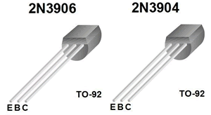
- Your previous experience with transistors, included part numbers
such as 2N3904 and 2N3906. The site you are looking at has transistors with
part IDs like
BC547
and
BC557. The transistors from the commercial solar light you dismantled,
had codes like S9013 and S9014. Google the phrase Reading Transistor
Markings,
discover the meaning of the leading letters, and summarize your findings.
- Go to this
site and study Circuit 2 in detail. This is essentially the
same circuit used in your commercial version. Circuit 2 describes a component
called an inductor. Explain what
an inductor is and provide
an
explanation of the role it plays in this circuit. In your writeup, include
the graphic that depicts the circuit symbol for an
inductor.
If you were driven to school
today, you probably passed over a large inductor. Research and explain in
your own words, what connection there is between and inductor and a traffic
intersection.
- Examine this simplified bright white
LED circuit (Bright
White LED Specifications). Using parts from various
sources (EG, SGL, and additional parts you have been provided with) you are
to build this circuit and have a photo
taken
of the
operating
circuit on Tuesday April 8th. To be successful you will need to
build an inductor. Here is a graphic
explanation of how to build a simple centre-tapped inductor based on a
ferrite bead and
magnet (transformer)
wire.
Activity 9. Solar Circuit Analysis
After opening up the Solar Garden Light, take a very close look at the mini
circuit board that form the 'guts'. While taking a very close look at the components,
with a magnifying glass if necessary, download and complete the file, CircuitAnalysis.doc.
In completing the table, you are asked to provide extreme detail, researching
the part numbers, including the printed PCB indicator (C1, Q1, R1,
etc.), summarizing the important details in the Description column,
and proving a hyperlink to a datasheet, chart, or definition on the web in
the last column under WebLink.
Add the completed page to your CR, update your TOC, and submit by the deadline.
2008-2009 Practical Exam: Light Meter
 Create one last entry in your CR entitled Practical Exam - Light Meter.
Along with a half-page explanation of the circuit, include a copy of the adajcent
schematic and your
thumbnail photo.
Create one last entry in your CR entitled Practical Exam - Light Meter.
Along with a half-page explanation of the circuit, include a copy of the adajcent
schematic and your
thumbnail photo.
- For the students listed below, include a link to
http://darcy.rsgc.on.ca/ACES/TEE2O/Exams/0809EvilGeniusPractical/StudentVideos/XXXXXX.avi
where XXXXXX is your name as it appears in the directory below.
- Add the completed page to your CR, update your TOC, and submit by Tuesday
February 10.
Activity 6. A Rolldown Counting System
This final activity explored the basis for many digital devices: counting
and display. Start your writeup with a big picture Theory section,
written in your own words, any time after we finish the entire sequence, on
January 23. In each of the six major stages, as titled below, include a Purpose section
describing in detail, how each stage contributes to the sequence.
A. Analog Input
- Purpose (discuss the PB switch, maximum and minimum voltage levels,
zener diode, RC circuit, analog output)
- Include your own CircuitMaker diagram of Figure L34-6, right aligned to
support your discussion.
B. Voltage Controlled Oscillator (VCO 4046)
-
Purpose
- Explain, in detail, the function of this chip (Input, Processor, Output)
- Explain the concept of analog input to digital output and how this
chip accomplished this
- Include
a table explaining the use of each of the pins that are in use in this
IC
- Pinout diagram taken from the web (include hyperlink citation)
- Digital Photo of 4046 VCO Circuit (Figure L35-1)
C. Decade Counter (4017)
- Purpose
- Explain, in detail, the function of this chip (Input, Processor, Output)
- Explain what it means to ensure that the input pins must be conditioned and
how this is done
- Explain what a clock signal is
- Explain, in your own words, the concept of input bounce and what negative
effect it could have on our counting system
- Pinout diagram taken from the web (include hyperlink citation)
D. Decimal Counting Binary Up/Down Counter (DCB 4516)
- Purpose
- Explain, in detail, the function of this chip (Input, Processor, Output)
- Create a two-column table with rows for all 16 4-bit binary values in the
left column and their equivalent decimal values in the right column
- Pinout diagram taken from the web (include hyperlink citation)
E. Binary Counting Decimal Decoder (BCD 4511)
- Purpose
- Explain, in detail, the function of this chip (Input, Processor, Output)
- Explain the purpose of the Blank, Store, and LampTest pins and how they must
be conditioned for normal use.
- Pinout diagram taken from the web (include hyperlink citation)
F. Seven-Segment Display
- Purpose
- Explain, in detail, the function of this component
- Explain the difference between the Common Anode (CA) and Common Cathode (CA)
versions of this component. Which one did we use?
- Explain the process by which you mapped the device (ie. how you determined
which pin corresponded to which LED)
- Graphic (google a similar small image)
- Pinout diagram taken from the web (include hyperlink citation)
|
Finally, include a digital photo and video of your complete
working system.
The Scope Probe - Activity 9
For this Activity, the Test Point will be at Pin 10 of your 4011
NAND Chip. After completing the assembly of your scope probe, use it with your
NAND
Gate Oscillator Circuit and one of the computers in 302 (do not attempt
this using any other computer at school) to obtain both
a
Winscope
screen capture and the data (File|Save
data...) while Winscope is on Hold (Pause button).
Your CR writeup is to include the following sections and details,
- Purpose
- Theory
- Reread pp. 99-101. Then, in your own words, discuss how your probe,
your sound
card and Winscope
2.51 all combine to monitor the logic levels at the Test Point.
- Procedure
- Digital Photo of your Probe
- In Winscope, under Options, set Data file... as follows,
-
Winscope capture of the sample (Active) interval.
- Import the saved data from the selected interval into Excel and use
it to chart a graph similar to the one depicted by Winscope. For example,
9. The NAND Gate Oscillator
Include the following,
- Purpose
- Theory
- Procedure
- Digital Photo
- CircuitMaker diagram of Figure L24-1 that includes details of
Parts Used (see Table L24-1)
- Tracking Table. Copy and complete Table L26-1 with results obtained
by experimenting with suggested components
Submit
your CR.doc as
an attachment to an email to handin with the Subject
Line: Circuit Report.
Voltage Dividers - Activity 8
In this activity, you are asked to create an Excel Applet that can be used
to determine the Midpoint voltage between two resistors. A useful feature of
the Office Suite is that it permits the embedding of Excel Objects (and others)
directly into a Word Document. Your applet can then be interacted with, while
the reader is in Word. To successfully embed the Excel applet, create the
worksheet in Excel first. Then go to Word and select, Insert > Object...;
go to the Create from File tab and browse to the Excel file
containing the Applet. It should import the worksheet. Double-click to activate
it.

Activity 5b. Worksheet Integration
In this activity, you are asked to seamlessly incorporate the completed Inside
Gates worksheet
into your CR. Update your Table of Contents by the deadline.
Activity 5. The Astable Multivibrator
(AM) Circuit
 In
this assignment you are asked to document your investigation of three variations
of a common circuit known as an astable multivibrator (aka. a blinking
circuit). Since you are free to use any combination of resistors and capacitors,
it is
highly unlikely that your experiments and results will be the same as any
of your classmates. Under appropriate headings and using features from Word's
Equation Editor and Excel's Math Formulas,
include the following in your ER writeup,
In
this assignment you are asked to document your investigation of three variations
of a common circuit known as an astable multivibrator (aka. a blinking
circuit). Since you are free to use any combination of resistors and capacitors,
it is
highly unlikely that your experiments and results will be the same as any
of your classmates. Under appropriate headings and using features from Word's
Equation Editor and Excel's Math Formulas,
include the following in your ER writeup,
- An opening paragraph explaining the operating principle of the astable
multivibrator
- The adjacent schematic of the astable multivibrator
- A digital photo of your prototype (taken on Tuesday December 1)
- A link to the
online animation.
- A full table of parts for your Circuit C below.
- A graphic of the
mathematical determination of the frequency, f,
of the period of oscillation for your Circuit C below, using Word's
Equation editor. The general formula is,

- A results table created in Excel will summarize the characteristics
of the two symmetric AM circuits (R2=R3 and
C1=C2) and one asymmetric AM design (R2≠R3 and
C1≠C2). It is expected that you
will choose RC combinations that lead to easily observable
times. The
graphic below provides an example of what your table should look like.
Note: The values in the last 6 columns are the result of evaluating
the proper formulas.

- A Conclusion
- Update your TOC.
Attach your ER.doc, the Word document you used to create
your equation and the Excel workbook used to create the results
table to an email to handin with
the Subject: Activity
5. The Astable Multivibrator Circuit by the requested deadine.
Activity
4. Professional Style Alarm System
 Your writeup for this activity will include,
- Circuitmaker graphic of Figure
L12-7 (adjacent).
- Digital photos of the front and back of your soldered PCB (to
be taken on Wednesday November 25 and Friday November 27.)
- Provide a link to Figure
L12-7, the animated alarm.
- Type in the Exercise questions 1-8 from page 45 and merge in these
answers using your deluxe formatting skills. You are responsible
for understanding these supplied answers as they may be part of the next
assessment.
- Update your TOC.
Submit
your ER.doc as
an attachment to an email to handin with the Subject: Activity 4.
Professional Style Alarm System
Activity 2. The NPN Transistor
This is a major assignment. You will be given ample
class time to gather the necessary data and develop a quality submission.
If you use the time I'm giving you wisely, you will be rewarded.
Include a digital photo clearly showing the parts and their connections and
this image
of the Figure
L9-7 ( DO
NOT DRAG AND DROP OR I'LL SEE SOMETHING LIKE THIS) in support
of an ER entry
of the Exercise: Introducing
Transistors on page 32. To facilitate your effort, insert the unformatted
questions into your ER and using superior formatting skills (hanging
indent, format painter, justification, etc) combine the questions with
your detailed
responses.
Be sure to include the tables in the second column of page 2
using your vastly improved table formatting skills as
we discused in the feedback from Activity 1. Update your TOC.
After ensuring all corrections
have been addressed from your previous submission (without removing
my comments)
submit your ER.doc as
an attachment to an email to handin with the Subject Line: Activity 2.
The NPN Transistor,
by the deadline.
Table L5.1
Using your DMM, undertake and record the measurements requested in Table
L5-1 at
the end of Lesson 5: The Effect Resistors have on a Circuit in your
workbook on page 17.
At the top of the page following the end of your Activity 1. Measuring
Voltage writeup, add Appendix
A-Tables and Exercises in Heading 1 style. Two paragraphs later, add Table
L5-1 in Heading 3 style. In this section create, optimize, and centre-align
a table similar to Table 5.1 that contains your readings. Don't forget
to update your Table of Contents (TOC).
Attach your ER to an email to handin
with the Subject Line: Table L5-1 by the deadline.
3. Circuit L8 - Activity 2
Write up your responses to the questions about Circuit L8 from pages 28-29,
in a manner similar to the process in class today. Submit your CR.doc as
an attachment to an email to handin with the Subject Line: Activity
2.
Complete Steps 1 to 8 on page 12, recording the results in the spaces provided, before completing the Activity below.
Activity 1. Measuring Voltage
[Insert a photo of your circuit, no larger than 200 px wide, right
justify and add a border]
[Include as is] As electrons flow through a circuit, voltage
levels decrease as the current (which remains constant) passes through successive
electronic components.
Reference
[Include as is] Adapted from Lesson 3: Your First Circuit. Evil
Genius: pp. 9-12.
Purpose
[Include as is] To learn how voltage levels are affected as current
passes through passive electronic components in a circuit.
Theory
[Include as is] Batteries are rated for a given voltage. The battery
in your family car is 12V, whereas typical flashlight batteries are 1.5V.
The rectangular battery in your household's smoke detector is 9V.
To perform the task for which an electronic component has been designed,
voltage is consumed. The circuit
designer must therefore ensure that recommended
voltage levels are achieved if components are to meet their upper operating
limits.
Procedure
Using the DMM, complete Steps 1 to 8 as directed on page 12. Enter your
measurements
Conclusion
If you have performed the Activity correctly, the conclusion should be apparent.
Explain the fundamental concept of voltage drop in a working circuit, clearly
and succinctly in your own words
~~~~~~~~~~~~
Task. Complete the above Activity and write it up as the first entry
in your Engineering
Report. Include the Title, Reference, Purpose, Procedure ( full
sentence answers to Steps 4 to 7, laid out as a numbered list), and
Conclusion. Don't forget to create and update a Table of Contents with
the Title and subsections as entries
for the Activity.
Each student is asked to submit his ER.doc as an attachment to
an email to handin with the Subject: Activity 1. Measuring Voltage by
the required due date.


 Wednesday May 7. Final Flashlight Assembly.


