Project 5. Final Exam
Your final ER entry for this course appear under the heading Project 5. Final Exam.
- The title, Project 5. Final Exam in Heading 1 style.
- Subsections in Heading 3 Style that include, Reference, Procedure, Supplemental Parts List, How It Works, and Media. The How It Works section should begin by explaining, in detail, the role played, by the NAND Gate Oscillator up to, and including, Pin 10 of the 4011. After that, include a discussion of any existing, and new, components.
- Support your text with a strategic selection of graphics of your choice taken from the exam and/or our course page, if necessary.
You do not have to submit this effort until 9:00 pm on June 3.
Project 5. The NAND Gate Oscillator (Fall 2014)
(This
is your second-to-last ER Submission for this course) Given you have already have a working NAND Gate Oscillator and that it is the foundation for our Final Exam, you can develop an ER entry for this project over the holidays. This means you won't have to complete during the exam on January 19th. For this entry, include the following,
- The title, Project 4, The NAND Gate Oscillator in Heading 1 style.
- Subsections in Heading 3 style that include, Reference, The 4011 Quad, 2-Input NAND, How It Works, and Media. The How It Works section should explain, in detail, the role played, and timing of, the two RC subcircuits, RC1 and RC2.
- Support your text with a strategic selection of graphics of your choice, taken from our course page, if necessary.
You do not have to submit this effort until 12:00 pm on January 19.
Project 4. Digital (Transistor-Based) Logic Gates
For this submission you are asked to,
 Merge the Word document, Inside Gates, into your ER on the first page after Project 3, retaining the landscape orientation of the document. Be sure to format all the requirements below into this single page, scaling as necessary, but retaining maximum eadability.
- Ensure your ER header and footer elements run through the page, adjusting the tab stops as necessary to accommodate landscape orientation.
- Set the title to your Heading Style.
- Adjust the cell shading to be consistent with your previous preference.
- Complete the Fritzing Diagram, Name, Symbol, and Truth Table for each of the remaining three transistor-based gates.
- Be sure to update your Table of Contents prior to submission.
Project 3. The Automatic Night Light
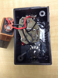 This is a major project in that after a successful prototype build on your breadboard you will assemble a permanent version by soldering the components to the custom printed circuit board in your kit. After that, you will mount the unit in a project box. Since you will be submitting a full ER entry for this project, you will document the build process with photos and video as it evolves. (Another objective of this project is to start you thinking about your personal ISP project that will require you to reserch/envision a circuit to build, assemble, and present)
Your writeup for this Project will include,
- Purpose, Reference and Procedure subsections (Heading 3 Style) with appropriate content.
- Fritzing schematic view of Figure L12-1 (right).
- Fritzing breadboard view of Figure L12-1.
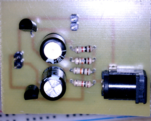
- Clear photos of front and back of your soldered PCB
- Questions and your full sentence, hanging indent-laden, responses to
#'s 2, 3, 6, 7, 9, and 10 on pp. 44-47.
- Photos and a video of the complete circuit development process and result.
Address, but do not remove, the concerns expressed
in ALL my comments embedded in your ER.docx from the last submission.
Submit your ER.docx as
an attachment to an email to handin with the Subject Line: The Automatic Night Light
Additional photos of Mariano's build: ANL4, ANL5, ANL6, ANL7, ANL8, ANL9
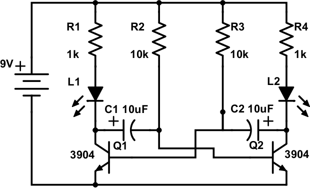
Project 2. An Analog Oscillator
 An ACE alumnus, Cole Norton (RSGC '14), prepared and delivered a workshop for interested Georgians on the use of an analog oscillator that could be used to create blinking eyes in a Halloween pumpkin.
A few current ACES, Graham Trusler, Ata Ettehadieh, and Mariano Elia, pitched in to design, etch, drill, and cut printed circuit boards to support your first soldering project that, if executed carefully and efficiently, could be put to good use this Oct 31 on your front porch.
Task.
 Clean the lens of your phone's camera, as you will be gathering media (photos and videos) throughout this project, from start to finish, in support of your ER project summary due Saturday November 1.
- This project will test your organizational abilities as much as your nascent electronics' knowledge and skills. You have been supplied with a bag containing a sufficient number of parts to prototype this circuit. Part of the task includes thinking deeply about what you're doing. In support of this aim please be aware that replacement parts will not be supplied by me.
- After studying the schematic of this oscillator circuit, and reviewing the parts list on page 2 of Cole's handout. undertake the assembly of the analog oscillator (blinker). When you are confident the circuit has a chance of functioning, apply the 9V regulated power. Debug as necessary and document the results with your phone's camera.
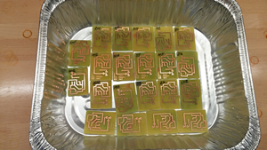
- Once you have obtained your media, you can request the additional parts that include a printed circuit board (PCB), a DC power jack, two pairs of male header pins and two 6" paired wires. Dismantle your prototype and dry fit the parts on your PCB in a manner similar to the image to the right (click to enlarge).
 With your soldering area fully equipped with easy access to the required tools and conscious of the soldering techniques and strategies discussed in class, you may begin the soldering stage. Remember,
-
Never solder with the power plugged in.
- Your soldering station should be kept no higher than 300°C.
- Keep the parts as tight to the surface of the PCB as possible. The reverse tweezers can help with this.
- The soldering tip should be clean and tinned.
- Any longer than 4s with the soldering tip on the leg of a component runs the risk of damaging the part!
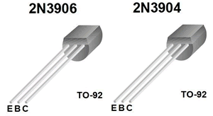
- Solder the smaller components first: resistors, then transistors, then pin headers, then DC jack, and finally the capacitors.
- On multi-legged semiconductors, it is good practice to solder one leg, solder another part, then return to the original part. This practice minimizes the cumulative heat effect on parts.
- If you have invested care and thought into your efforts, plugging your 9V adapter into the DC Power Jack should yield the desire outcome: a pair of blinking lights. If it doesn't function as expected, prepare yoursefl for the best part: debugging. Seriously, nothing is as rewarding that analyzing and repairing a faulty system. Use the large illuminated magnifying glass to check all your solder joints. Confirm your polarized parts are in the cirrect way. Use the DMM to to perform continuity, voltage, and integrity inspections. You'll find the problem without the need to ask my opinion.
- ER. Starting on a new page, add the Project name and complete sections under the headings: Reference, Purpose, Parts List, Procedure, and Media. Text developed in accordance with the recommendations for Technical Writing and reflective your strong formatting abilities is a must.
- Attach your ER to an email to handin with the Subject: An Analog Oscillator by the deadline.
Project 2. Capacitors and Push Buttons
By now you have had time to address all the issues associated with the previous ER submission, including the ones we discussed in class and that also appeared in my Feedback email to our TEL3M subject conference on February 15, 2015. I'll be looking to see that these have been completed.
Pages 30-31 present a summative exercise based on a relatively simple circuit involving capacitors and push buttons. Starting on the first full page AFTER Project 1, you are asked to complete the following tasks as your second formal ER submission.
- Include the title, Project 2. Capacitors and Push Buttons, in Heading 1 style.
- Using your strong formatting skills, in particular, your use of the hanging indent feature, enter both the questions and your response for each of the 6 steps.
- The questions should appear in a plain face, with your answers appearing in italics, immediately following the question.
- A graphic of the schematic and the completed table in alternating row background shading should appear right-aligned on the page and neither should be more the 3" in width.
- You are to limit the writeup for this exercise to no more than a single page.
Project 1. Measuring Voltage
NOTE: Substitute all references to a '9V battery' in the workbook with a 9V Adapter.
Engineering Report
- Review the Engineering Report General Guidelines.
- Each Project writeup starts on a new page.
- For this project subsections must include Reference (Include a hyperlink containing the URL of this project description), Theory, Procedure (complete Steps 4 to 8 ), and Conclusion.
- Develop Fritzing images similar to the ones above for inclusion in your submission and store them in your images folder.
- Appropriately-sized and formatted photos and diagrams are to be right-aligned and embedded at strategic locations within your writeup.
- A link to a video summary of the Project, posted to YouTube, will appear within your Conclusion.
- Update your Table of Contents.
- Attach your Engineering Report to an
email to handin with the Subject: Measuring Voltage by
the required due date.
Your text should be developed in accordance with the recommendations for Technical Writing.
 This is a major project in that after a successful prototype build on your breadboard you will assemble a permanent version by soldering the components to the custom printed circuit board in your kit. After that, you will mount the unit in a project box. Since you will be submitting a full ER entry for this project, you will document the build process with photos and video as it evolves. (Another objective of this project is to start you thinking about your personal ISP project that will require you to reserch/envision a circuit to build, assemble, and present)
 An ACE alumnus, Cole Norton (RSGC '14), prepared and delivered a workshop for interested Georgians on the use of an analog oscillator that could be used to create blinking eyes in a Halloween pumpkin.
 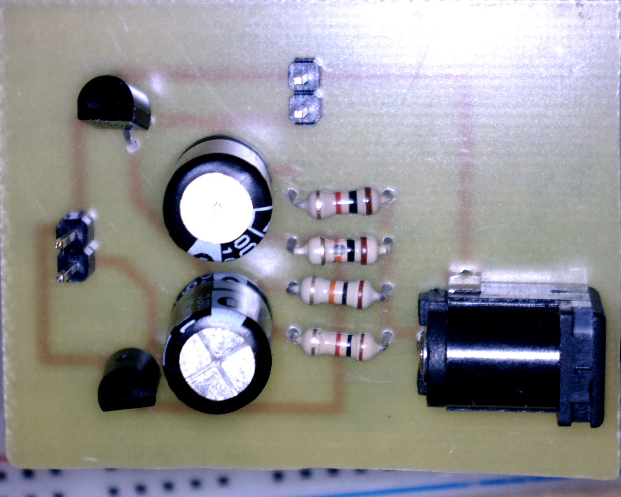 Clean the lens of your phone's camera, as you will be gathering media (photos and videos) throughout this project, from start to finish, in support of your ER project summary due Saturday November 1.
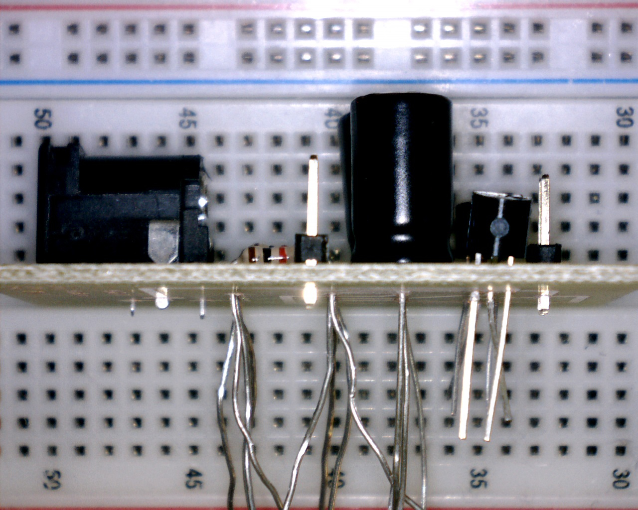 With your soldering area fully equipped with easy access to the required tools and conscious of the soldering techniques and strategies discussed in class, you may begin the soldering stage. Remember,