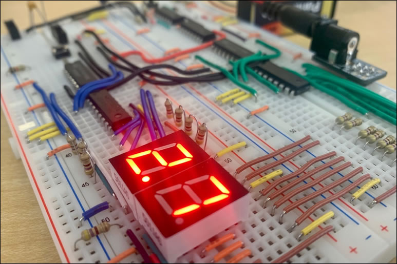
 You will recall that our first course placed a premium on the BUILD quality of your breadboard prototypes, as G. Davidge's (ACES '24) example to the right reflects. Yes, quality takes time, planning, and care but the manintenance dividends are substantial. This expectation of QUALITY continues in your hardware pursuits and expands to include ACES' other two preferred domains introduced in our second and third courses: software and design.
Software and hardware form the backbone of modern telecommunications. As you begin your second course within RSGC's ACES program it is your teacher's intention to place you on the best footing from the outset to ensure your achievements are optimized for performance and to develop habits that will stick with you for life, no matter where it leads. To do so, requires tradeoffs at every stage of growth and development, as your skills mature. This is a familiar pattern that will repeat itself for as long as you pursue a craft of any sort in that, the farther you travel down a road, the more you understand, inviting you to regularly reach for the Reset switch.
The motivational brilliance behind the development of the Arduino Platform included providing curious minds with simple, seamless access to the power of electronics based on the (AVR) microcontroller. To flatten the learning curve, the developers had to, necessarily, hide many of the complexities that would have made the curve too steep for beginners. ICS3U-E ACES are no longer beginners and aiming their futures towards undergraduate engineering programs. It is time to draw back the curtains that hide many of the Arduino's critical details, thereby opening their own doors to efficiency and optimization of the platform.
With months of code development ahead of you will eventually come to appreciate the areas of concentration below, many of which were prompted by reading the code ACES that have gone before you have included in their DERs or were highlighted in their videos.
0. Orientation/Configuration of your Arduino Software 'Integrated Development Environment' (IDE)
 There are many tools to develop software for your Arduino (AVR MCUs) but their basic IDE is the best utility for ACES to start with as it offers realtively easy access to many fundamentals resources that combine to produce and flash executable code. To maximize and optimize your Arduino IDE development cycle there are a few features that we need to consider, once your IDE is installed.
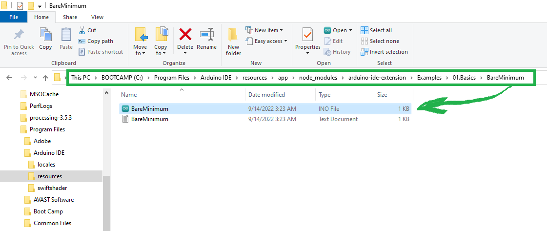
- Mac Hard Drive Scavenger Hunt: Arduino IDE installation: Examples Folder?
- IDE Menu: File > Preferences > Sketchbook Location > ....
- IDE Menu: Edit > Copy as HTML (W3 Schools Try It!)
- IDE Menu: Sketch: Upload Using Programmer, Include Library
- IDE Menu: Tools > Board, Port, Programmer
- Arduino Source file (aka sketch) extension: .ino
- BareMinimum.ino
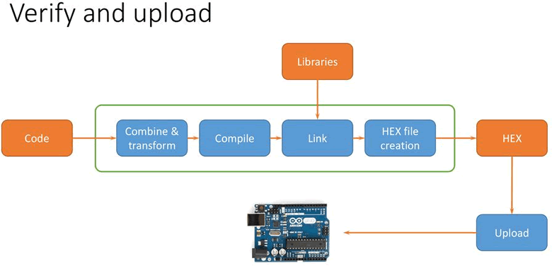
 1. The Arduino IDE's Verify and Upload Buttons
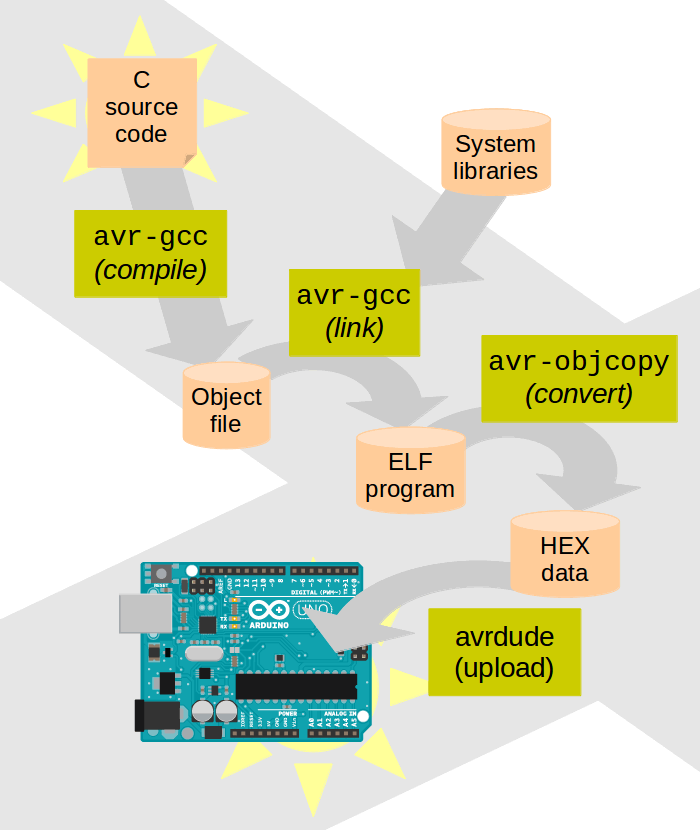
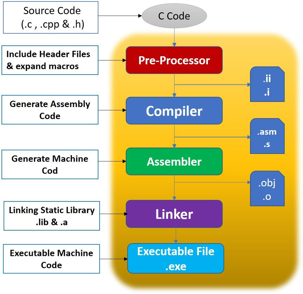
- It wouldn't hurt to reacquaint yourself with the Arduino Toolchain.
- Arduino C's Sketch Host: main.cpp [p. 138] (aka. Are setup() and loop() really necessary?)
- AVR-libc's Online Documentation
2. Better Decision-Making
- In C (and most languages), the integer 0 is equivalent to false. Any non-zero integer is equivalent to true. Since a successful digitalRead() statement can only return either 0 or 1, simply code,
if (digitalRead(sensorPin))
rather than
if (digitalRead(sensorPin) == 1)
 Some bad coding habits may be a result of tradeoffs required to get more Arduino users up and running quickly and successfully. Consider the first example in the Strings suite of sketches within the Arduino IDE, CharacterAnalysis. Rather than include the use of the mutually exclusive if..else ladder, the designers opted for the less-efficient (easier to read ?) sequence of ifs.
 - Imagine that a coder's intention was to develop an if..else ladder to obtain the letter following the users' input for 'A' through 'E', otherwise assign a value of '?' to nextChar. Here's his first attempt. What is the value of nextChar at the end of this attempt for each character input ?
  while (!Serial.available()) {
    ch = Serial.read();
    if (ch == 'A')
      nextChar = 'B';
    if (ch == 'B')
      nextChar = 'C';
    if (ch == 'C')
      nextChar = 'D';
    if (ch == 'D')
      nextChar = 'E';
    if (ch == 'E')
      nextChar = 'F';
    if (ch != 'A')
      nextChar = '?'
    }
Here is the corrected version of the above if..else sequence. An even better way is to forget the if..else ladder and employ a switch..case statement.
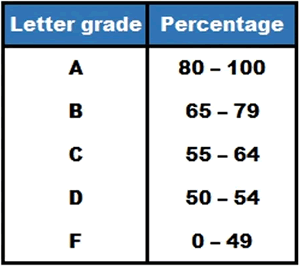
- Imagine the coding task of converting from a percentage to a letter grade.
 Let's explore how Excel's VLOOKUP() function offers a solution in this example.
- Let's develop a correct if..else ladder in Arduino C to handle the problem.
3. Functions. See here...
4. Menus
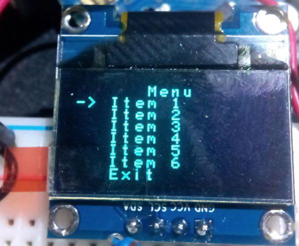 A common code requirement of many UIs that deserves some attention is the menu. Presentation and response-handling are two of a number of considerations we'll explore in this segment. To keep things simple we'll employ a character-based approach using the Serial Monitor. Graphic adaptations for LCDs, and OLEDs are left to your own efforts.
When it comes to iteration, limit their implementations to one of two alternatives: the (0..many) conditional while() loop and the 'unconditional' for() loop. There is a seldom-used useful third option for 1..many situations: do..while() that is ideal for this situation.
- Create a new Arduino Project called DoWhileMenu and drop in this code.
- do..while. The while and for loops provide the more common iteration statements in most languages. A third option is the do..while statement. Menus are an ideal use for the do..while loop style.
- This sketch uses the F() macro to place the output strings in Program Flash.
- The embedded \t and \n codes within the literal strings, defining the tab and carriage return/newline respectively, are two of a number of useful escape sequences. Review the others.
- Recall that users must press Return in the Serial input box to trigger the reading. In so doing, a newline character (ASCII-10) is inserted into the keyboard buffer. This character must be removed (and typically tossed aside), for the accurate reading of subsequent input.
- This example provides for an unlimited number of erroneous input attempts. It would be a simple matter to weave in a maximum number of incorrect attempts and add an additional condition to the detection of the 'X' or 'x', to exit the menu.
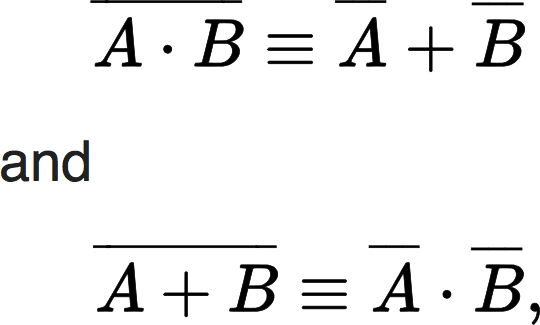 De Morgan's Laws. If, while and do..while conditions form a common point of intersection between software and hardware logic. Just as expressions in mathematics benefit from simplification so, too, do boolean expressions. The British mathematician/logician Augustus De Morgan (1806-1871) introduced two theorems that can influence the simplification of logical expressions. Taken from Wikipedia, In formal language, the rules are written as.
`¬(PvvQ)⟺(¬P)^^(¬Q) and ¬(P^^Q)⟺(¬ P)vv(¬Q)`
where,
- P and Q are propositions,
- ¬ is the negation logic operator (NOT),
- `^^` is the conjunction logic operator (AND),
- `vv`is the disjunction logic operator (OR),
- `⟺` is a symbol meaning "can be replaced in a logical proof with".
- Review the C++ Operator Precedence (p. 140), if necessary, to confirm the equivalence of De Morgan's Laws.
5. Data Memory Options and Considerations
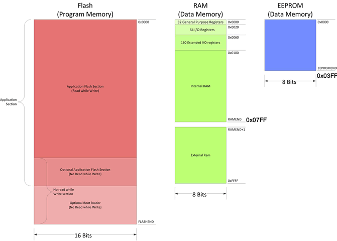 The 8-bit AVR family of MCUs offer three onboard memories: Program Flash, SRAM, and EEPROM. Whereas the sizes of these memories vary within the families, their nature does not. SRAM is volatile (contents lost when power removed) , Flash and EEPROM are non-volatile (contents persist when power is removed). Click on the image to the right to reacquaint yourself with the sizes of each of the three memories on the Arduino's ATmega328p.
The three memory clearly needs to accommodate both program code and data. Whereas your program code must reside in Program Flash, you can place your data in any of three areas! Knowing the sizes and access times for each are an important considerations in develop efficient applications.
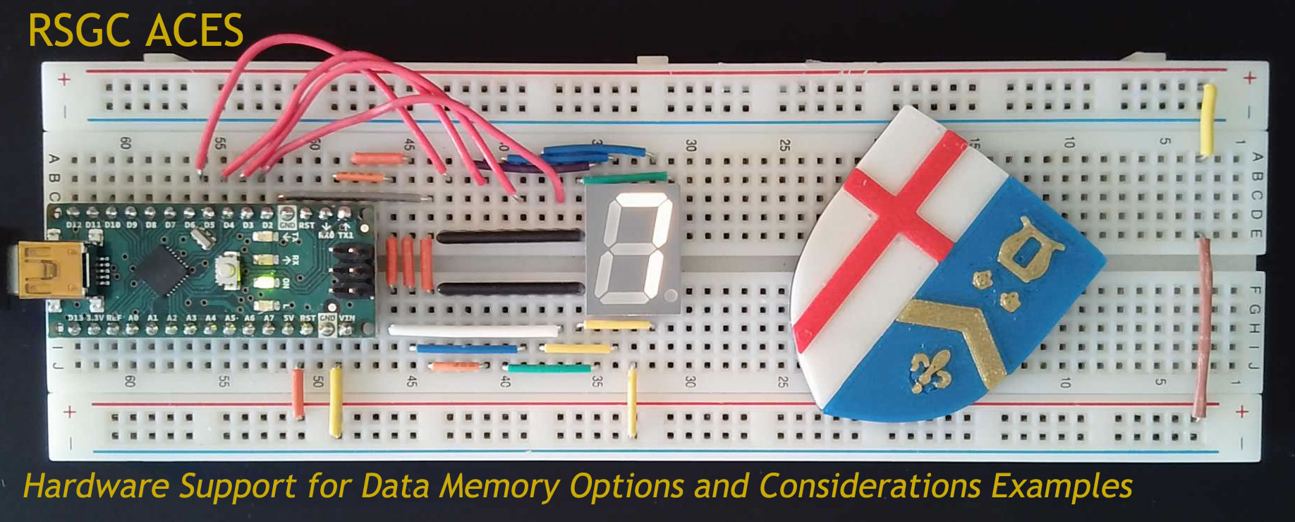
Exploration. In this segment of Towards Better Code we'll demonstrate the placement of data in each of the three memories and discuss the strengths and limitations of each strategy. For the data, we'll use a 10-byte array of segment maps for a common 7-segment display. Below is an image of the circuit you may wish to construct yourself if you have the means.
- SRAM. 7SegmentSRAM.ino
- EEPROM. 7SegmentEEPROMWrite.ino followed by 7SegmentEEPROM.ino
- PROGMEM (Program Memory). 7SegmentPROGMEM.ino. Reference: AVR-libc: Program Space Utilities
- Arduino's F() macro
6. C-Style Strings and Formatted Output
 Few of C/C++ coding concepts are as challenging as working with strings. Part of the problem arises from the fact that C and C++ handle strings differently; both being vulnerable to the particular dialect and compiler being employed. The philosophical foundation of the Arduino Project as cross-platform, open source, C and C++ compatible, and specifically tailored to AVR 8-bit hardware, was a tall order back in 2005, that came with tradeoffs. These noble goals envisioned by the Arduino/MIT community, embodied in the toolchain provided by AVR-libc, are what current Arduino developers must adhere to.
The Arduino core set of libraries includes WString. This library provides a String class that facilitates seamless manipulation of C-Style strings and you are encouraged to review both its documentation and set of examples within the Arduino IDE.
Since even a modest attempt to discuss the nuances of string handling in the Arduino C environment is beyond the time allotment of this segment, I will restrict my comments to a few general principles.
C-Style Strings
 We'll focus on the non-Class, C-Style implementation.
- Review the standard Arduino Reference for the string data type.
- C-style strings are little more than character arrays, as in char string[20];
- (Taken from here). A C-style string is a null (denoted by \0) terminated char array. The null occurs after the last character of the string. For an initialization using double quotes, "...", the compiler will insert the null.
- Except for str2 having more room, the following are all equivalent,
	char str1[]  = "hi!";                  // compiler can determine array size
	char str2[20]= "hi!";                  // plenty of room
	char str3[4] = "hi!";                  // min size, must allow room for null
	char str4[]  = {'h', 'i', '!', '\0'};  // the above are equivalent to this
- The Arduino Serial.print() function is overloaded to accept char arrays.
- AVR-libc's string.h library included in the Arduino core set, offers many functions to work on C-style strings, as the examples in this tutorial demonstrates.
Nevertheless, be prepared for some strange and inexplicable results.
- Here is another tutorial that attempts to explain a preference for the C-style null-terminated string over the use of the String class.
Formatted Output
The primary purpose of the previous glimpse of C-style strings was to lay the context for its application to structured formatting of text output, either to the Serial Monitor or other devices such as a character LCD or OLED display.
 |
 |
- Consider the LCD screen pictured above, left. Rather than outputting each piece of data to the display, one at a time, it is more efficient to compose the ENTIRE contents of each row in software first, as a C-style char array and transmitting it ONCE. The code fragment below achieves this. We'll review this in class.
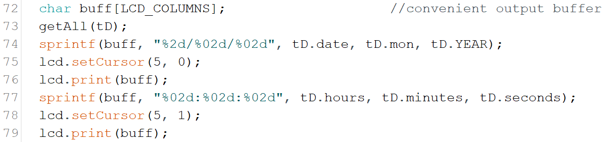
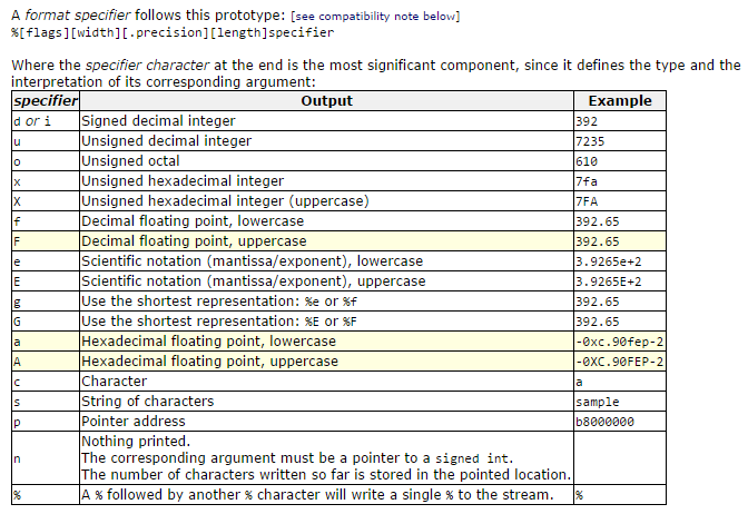
- The key to assembling a single, compact text string lies in the use of the sprintf() function, one of dozens included with AVR-libc's stdio.h library.
- Here is a third-party primer on the use of the sprintf() function: http://www.cplusplus.com/reference/cstdio/sprintf/
- Two keys leading to a successful implementation of the sprintf() function lie with the creation of a C-style string (as a char array) and the correct use of the available format specifier codes.
- Another interesting example is found on page 126 of your AVR Foundations Workbook. Review the concept of permutations of a set and create a project from the code found here: https://github.com/rsgcaces/AVRFoundations/blob/master/F_EMBEDDED_SYSTEMS/Permutations/Permutations.ino. We'll review this in class.
- We'll review the code above later in this session.
7. Pointer Access Operators (& and *)
 Like many coding topics, there are only limited resources within our course that can be allocated for discussions of purely software intricacies within a hardware course. On the other hand, in order to fill a huge gap in Ontario's Ministry of Education curriculum our ACES course attempts to fulfill the expectations of the software course code you are being granted (ICS3U). To this end, let's take a (very) brief look at C/C++'s powerful duo of pointer access operators, & and *. Microchip offers good explanations to begin with (although their navigation system is horrible)
- Data Pointers
- How Pointers Work
- Pointers and Arrays
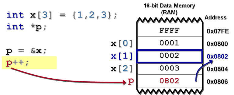
- Pointer Arithmetic
& - The Reference (Address of) Operator
- Create the Arduino project MemoryAllocation and drop in this code.
- We will review the code and examine the output in class.
- Call By Reference. Use of the reference operator is very handy for designing functions to achieve multiple changes by modifying the parameters.
- Create an Arduino project entitled, CallByReference, and drop in this code. We'll explore the code and the output in class.
8. Memory Issues
Your nascent familiarity with the reference operator, & assists us with a common memory issue. Resolving a recent issue with a student prompts me to comment on C and it's relatively loose array bounds checking.
Bounds Checking
- Create an Arduino project from ArrayMemoryIssues.ino
- Review the code, appreciating the use of formatted output and the reference operator, &
- Upload the sketch and review the output
- Note that no warning was ever issued by an attempt to index arrays beyond their declared bounds
- C/C++ programmers need to be more aware of memory usage than Java programmers, for example
Memory Allocation
- Within the same sketch, note that the memory assigned to the array undefined[] is (initially) unspecified
- Run the code, noting the memory addresses assigned to the arrays
- Remove the comments in the setup() function that assign values to the array, undefined and run the code again, noting the (strange) output
- Adjust the declaration of the array undefined to ensure it is assigned sufficient memory from the outset.
- Run the code again, noting the improved output
- In summary, to avoid inexplicable errors, given C's loose memory bounds checking, it is likely best to ensure sufficient storage is allocated to data arrays at the moment of definition.
9. Data Smoothing
10. Register-Level Digital I/O
 The software capabilities afforded by high level Arduino C offer users a learning curve with a fairly gentle slope. Your marvelous Grade 11 prototypes are visually-inspiring testaments to what your imagination and ingenuity have managed to do with the C as the software tool.
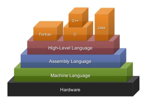
As ACES II winds down and some of you prepare to engage ACES III, the time is right to refocus our priorities on the optimization of the AVR-8 microcontroller. In this way your embedded systems will take up less memory, run faster and draw less power, among other advantages. This path is best served next year by introducing a lower-level software tool that offers closer access to the circuitry of the MCU. Microcontrollers and CPUs have a native language called Machine Language that would require the embedded engineer to code in binary or hexadecimal. Since this would be too painful and time-consuming an exercise MCU/CPU manufacturers offer a language that is just as efficient as machine language and avoids the bulkiness of high-level C. This language is referred to as Assembly Language which we will introduce in ACES III.
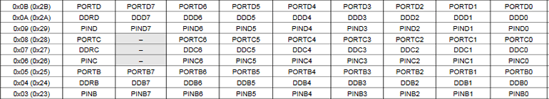
 The embedded engineer requires a strong grasp of the hardware architecture of the target device. In this segment of Towards Better Code you take your first steps in drawing back the curtains that high-level C coding has imposed to manipulate the ATmega328p's digital I/O pins directly. As was discussed in class, each of the AVR MCU's digital I/O pins are mapped to a triad of 8-bit registers. These registers are located in SRAM as can be seen in the graphic below. The triad of registers are called, PINX, DDRX and PORTX, where X is either B, C, and D. The Arduino Pin Mapping diagram to the right reveals the connection between the high-level pin numbers (red) and the corresponding lower-level register bits (black).
Our introductory examples in this section will continue to use C as the code base, but since the header file iom328p.h is included in the Arduino C toolchain, our high-level code can refer to, and manipulate, individual bits of the I/O register triads, by name!
Register-Level Input
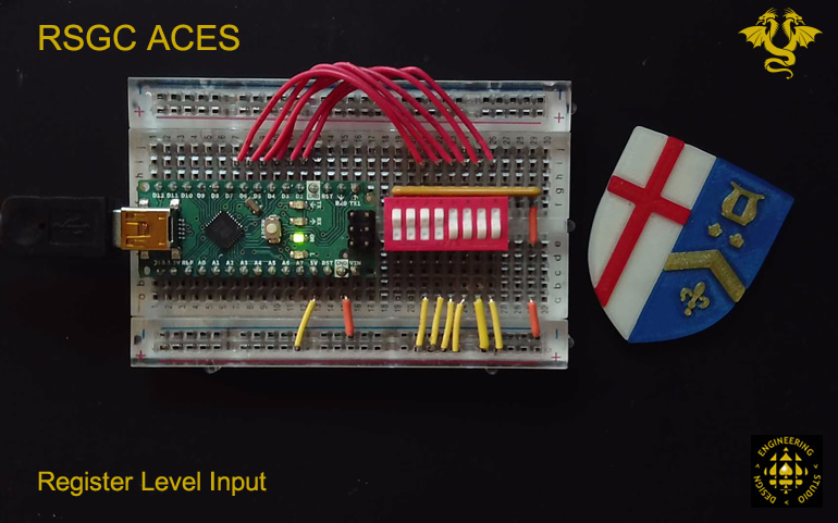
To complete this introduction to register-level IO it is necessary to provide an example demonstrating the use of the PINX register of the ports' triad of registers. To this point in the course, buttons or other digital devices generating digital signal states have been read using Arduino C's digitalRead() statement. This example will demonstrate the digital input using a register-level approach.
- Consider the hardware platform below. The rightmost six switches in a DIP rocker bank have been configured using a pull down resistor network to provide a LOW when the switch remains OPEN. When a switch is ON a HIGH signal is read.
- Each of the six switches are wired into PD2-PD7. This frees up PD0 and PD1 for Serial communication support AVR ISP and Serial Monitor output.
- Create an Arduino project, RegisterLevelInput from this code. The program uses a 2-second Timer1 interrupt to simply read the input state of Port D and displays the result to the Serial Monitor for confirmation.
- Listen to the explanation in class that follows for further details.
11. Reusable Code - Your Own Custom Library
 Imagine for a moment, if a stipulation of our ACES version of ICS3U-E back in September precluded the use of third-party libraries. It would be doable, but progress would be slow. Libraries introduce a tradeoff: they hide the complexities (aka. abstraction) of a device or application in exchange for end users' ease-of-use. We've reached the stage in our course where it is time to examine the process of developing your own libraries as sources of both abstraction (aka. black box) and reusable data and code.
In programming for the ATmega328P (either the UNO or Nano) you became familiar with predefined constants such as, LED_BUILTIN. Tucked deep inside your Arduino IDE's installation, and included automatically in the toolchain, is a library file, called variant.h, that contain this statement (and numerous others),
#define LED_BUILTIN 13
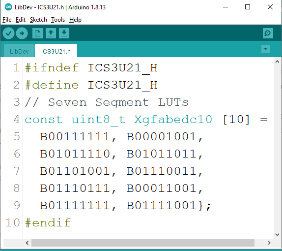
Libraries are an integral part of the development cycle as they reduce development time and ensure greater code accuracy. It would be both instructive and efficient for you to begin to assemble reusable software assets inside your own library of support resources. For our immediate generic purposes we will name our library, ICS3U21.h
- A common data array is the one that defines the segment maps for a CC 7-Segment display. Easy access to it, from any project, would increase our productivity.
 Open the RegisterLevel7SegmentDisplay project from the previous segment and Save As... LibDev
- Select New Tab (top right), naming it ICS3U21.h which will be your custom library (the h stands for header)
- The contents of ICS3U21.h appears in the graphic, above right. The code consists of the data array used in Segment 4 above, wrapped in a preprocessor directive sequence. (Reference: AVR-gcc: List of Directives, Macros, and Options). Cut the definition of the segment map from the driver code and Paste it into the ICS3U21.h header file. Add the preprocessor directive sequence (beginning and end).
- Return to your LibDev driver and add the preprocessor direction that first looks for your library within the current project directory,
#include "ICS3U21.h"
- Upload the project and debug.
- Make your library accessible to all future projects. TBC...
12. Recursion: Setting the Stage
 Our final two classes together will introduce concepts that you will engage over the course of the next few years, starting with your Calculus course next year.
Iteration (aka looping) is an indispensable software technique that can be brought to bear on a wide variety of programming tasks that involve require a repetitive strategy. There are, however, numerous problems of repeatable form that do not lend themselves to loops. Network analysis and optimization on weighted graphs that require depth searching is one such context that does not lend itself to iterative approaches.
Recursion is the primary alternative to iteration. From a coding standpoint it is elegant and deceptively simple in appearance, however, its performance can be taxing from a hardware perspective, especially for MCUs. Indeed, recursion should never be used if an interative solution would suffice, due to the overhead recursion imposes to support it.
Finally, It takes practice to become proficient in its use but, when you eventually 'get the hang of recursion' you may very well begin to view the world, in particular nature, in a very different light. We'll start with some simple recursive algorithms/functions from the world of mathematics.
A. Task. A Gentle Introduction to Recursive Functions. (See pp. 124-127)
 Finite Sequences and Series: eg.`\sum_{i=1}^n \frac{1}{i} = 1+\frac{1}{2}+\frac{1}{3}+...+\frac{1}{n}`
 - Fibonacci: `t_1=1, t_2=1, t_n=t_{n-1}+t_{n-2}`
- Factorial: `n! = n*(n-1)*(n-2)*...3*2*1`
- Permutations: `P(n,r) = \frac{n!}{(n-r)!}`
- Combinations: `((n),(r)) = C(n,r) = \frac{n!}{(n-r)!r!}`
B. Task. The Binomial Theorem
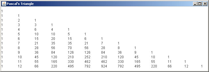
 Your familiarity with Binomial Theorem as a guided tool for the expansion of binomials in Grade 11. The formula also comes in handy early in your first Calculus course as it provides the foundation for the Power Rule for differentiation As a result, it doesn't hurt to take another look at the superimposed coefficients provided by Pascal's Triangle. First, let's restate the Binomial Theorem,
`(a+b)^n = \sum_{r=0}^n ((n),(r)) a^{n-r}b^r`
It is now clear that Pascal's coefficients can be computed directly `((n),(r))` as was done in the previous exercise. There is no need to develop the previous rows. On the other hand, there is great value is exploring how this could be done through a recursive approach. Elements `p`,of Pascal's Triangle, expressed recursively, can be defined as follows,
`p(n,0) = p(n,n)=1, p(n,r)=p(n-1,r-1)+p(n-1,r)`
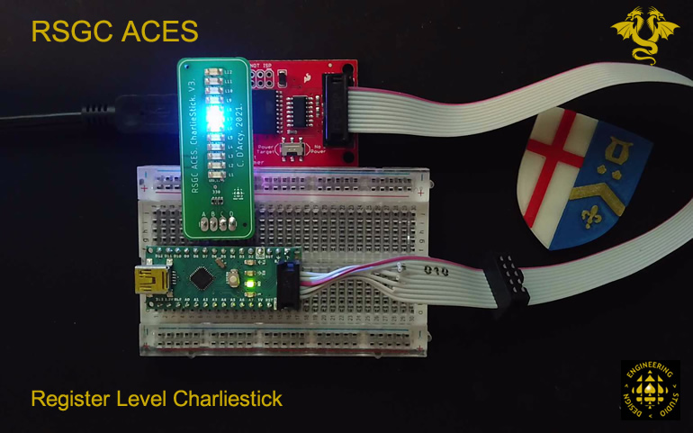
13. Charlieplexing on the RSGC ACES' SMT Charliestick
 The final segment of this Session encourages you to appreciate that both software and hardware techniques can be optimized for improved performance. What may alternatively be referred to as 'doing more with less' this demonstration takes a register-level software approach to port manipulation while exploiting the tri-state architecture (referred to as Hi-Z - impedance) of the AVR's digital IO pins.
While not intended necessarily to have these techniques find their way into your late Grade 11 projects, introducing them now will give you time to reflect and explore the concepts this summer as (some of) you prepare for the deepening study of embedded prototype development in our Grade 12 course.
 Microchip offers a summary discussion of AVR ports supported by a succinct
 Port Pin Summary video (<2:00) that is worth watching.
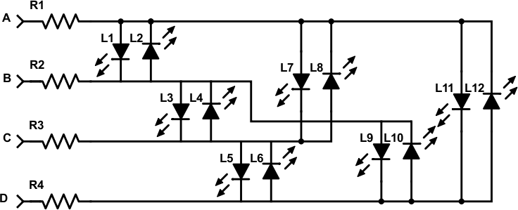
 - Charlieplexing (named after Charlie Allen) )is a technique that exploits the tri-stated architecture of the AVR's digital IO pins. ACES have applied Charlieplexing creatively in the creation of what we call the Charliestick. As can be sen from its schematic, only 4 digital pins are used to address 12 distinct LEDs. This is a terrific form of hardware optimization.
- The hardware prototype for this segment appears in the photo below (click to enlarge) and here is a video of the LED animation on the device. The SMT Charliestick can be seen connected to PORTD7-4 pins.
- Feel free to create the Arduino project RegisterLevelCharliestick and drop in this code: RegisterLevelCharliestick.ino
- Listen intently to the explanation and class discussion on these optimized strategies.


