Project 3. Digital (Transistor-Based) Logic Gates
For this submission you are asked to,
 Merge the Word document, InsideGates, into your ER on the first page after Project 2, preserving the landscape orientation of the document. Be sure to format all the requirements below into this single page, scaling as necessary, but retaining maximum readability.
- Ensure your ER header and footer elements run through the page, adjusting the tab stops as necessary to accommodate landscape orientation.
- Set the title to your Heading Style.
- Adjust the cell shading to be consistent with your previous preference.
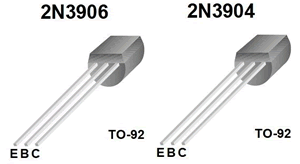
- Complete the Fritzing Schematic, Name, Symbol, and Truth Table for each of the remaining three transistor-based gates. Do NOT make any mistakes; it's too important!
- Be sure to update your Table of Contents prior to submission.
Project 2. The Automatic Night Light
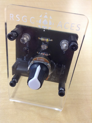 This is a major project in that after a successful prototype build on your breadboard you will assemble a permanent version by soldering the components to the RSGC ACES' PCB. After that, you will mount the unit in the permanent housing provided. Since you will be submitting a full ER entry for this project, you will document the build process with photos and video as it evolves. (Another objective of this project is to start you thinking about your personal ISP project that will require you to research/envision a circuit to build, assemble, and present to the class)
Prototype
- Be patient and assemble a quality prototype of Circuit 4.1. Take a high detail photo and video for your ER Summary.
- Data Gathering. Consider the Test Point shown in Red below. With a DMM, obtain and record voltage readings for the various settings described below.
- Set the pot to 0 Ω (wiper C all the way to A) and under fairly good light, measure and record the voltage at the Test Point.
- Now, obscure the LDR completely with a heavy dark covering and take another voltage reading. Explain the difference.
- Adjust your pot to 50k Ω (wiper C halfway between A and B) and repeat the previous two measurements. Record and discuss the results.
- Finally, set your pot to its full 100k Ω setting (wiper C all the way to B), and repeat the two measurements one last time. Record and explain your results.

ER. Your writeup for this Project will include,
- Purpose, Reference, Procedure, Media and Conclusion subsections (Heading 3 Style) with appropriate content.
- Include a background-shaded Parts List Table, right-aligned within your Procedure subsection.
- Incorporate the measurements taken earlier with your prototype into a response to Question 1 on page 38 of our Workbook.
- Fritzing schematic view of Circuit 4.1. You may use the one above as long as it is properly sized.
- Clear photos of front and back of your soldered PCB.
- Photos and a video of the complete circuit development process and result in action.
Address, but do not remove, the concerns expressed
in ALL my comments embedded in your ER.docx from the last submission.
Submit your ER.docx as
an attachment to an email to handin with the Subject Line: The Automatic Night Light
Project 1. Soldering Basics
 Before you begin your ER journey, please understand the rationale behind its importance.
- Engineers must be able to communicate. This encompasses appropriate vocabulary, writing style, formatting, media, interest and, above all, punctuality. This can only be undertaken with practice and strict attention to detail.
- Over the next few years you are going to invest hundreds of hours of planning, researching, designing, prototyping, and testing. An archival record of your efforts respects these investments.
- When you arrive at the doors of opportunity, they will ask you what you have accomplished. You can hand them a copy of your ER and they can judge for themselves what you have to offer.
Read over the Engineering Report Guidelines. The preferred structure of each Project Summary is much the same,
- Each Summary starts on a new page
- The title of the project appears in Heading 1 Style
- The subsections include Purpose, Reference, Procedure, Media and a Conclusion, all in Heading 3 Style
- A running header and footer (that includes the page number)
Project 1 Task.
- This project requires you to solder leads to a Potentiometer and a Normally Open Push Button (PBNO) if you want the practice. If you missed the class, watch this short video (
 Soldering Leads
to a Switch) and find time before Friday to document (photos and video) and complete the task in the DES.
Soldering Leads
to a Switch) and find time before Friday to document (photos and video) and complete the task in the DES.
- (ER)
 Starting on page (Arabic) 1, the title of the Project Summary is Project 1. Soldering Basics
- In the Reference subsection include a link to this description
- You are expected to write a brief Purpose subsection that reflects your understanding of the objective of the task. To get you started in this first summary, you could write something along the following lines,
Soldering is an essential skill in the field of electronics that involves a process of bonding two metals together. The purpose of this Project is learn basic soldering skills and to become familiar with the tools used in the process.
You can paraphrase what I have written if you like (do not copy it verbatim).
- In the Procedure subsection, include a written description of the soldering process that you undertook, from start to finish, writing in the present tense, Active voice. Reread the document Sentence Structure of Technical Writing, if necessary. Support your writing with a right-aligned Parts Table, and well-composed, high quality photos, right-aligned, preformatted to 3" in width. Add a 1px border to each photo. Borders are NOT placed around graphic image of components.
- Create and upload a short (1 min) YouTube video of your soldering session and include he link in your Media subsection.
- Include a single paragraph Conclusion subsection, written in the first person, in which you document your personal experience, challenges and learning and skill development.
Each student is asked to submit his ER.docx as an attachment to
an email to handin with the Subject: Project 1. Soldering Basics by
the required due date.