2024-2025 ICS4U-E Independent Study Projects (ISPs) |
![]() Independent Study Projects. Please read our overview on why ACES pursue Independent Study Projects so vigorously.
Independent Study Projects. Please read our overview on why ACES pursue Independent Study Projects so vigorously.
| Grade | Contribution to Final Mark |
|---|---|
10 |
30% |
11 |
40% |
12 |
60% |
For the bulk of your formal education you have been, and will continue to be, required to consume curriculum chosen for you by someone else. Hopefully you will put this knowledge and skill to good use in your future. However, jumping through someone else's hoops no longer secures future success. For that, you must put yourself in the driver's seat while in secondary school to both cultivate and demonstrate your own unique initiative, motivation, and passion. RSGC ACES program is explicitly built and tailored for you to foster these greater goals. Yes, there is much to learn but there are so many great projects to be undertaken and noble problems to be identified and solved that offer stimulating contexts within which to develop and refine your interests it will quickly seem more than worth the risk, effort, and cost.

 To my mind, the characteristics of a great project include such aspects as imagination, creativity, a degree of risk and, sometimes, even simplicity, to name a few. Check out the flashlight circuit 'board' this guy made out of little more that a piece of paper and a pencil? Simple, but inspiring.
Consider a problem that needs a solution. Boyan Slat did at age 17 when he was in high school; four years later he is
To my mind, the characteristics of a great project include such aspects as imagination, creativity, a degree of risk and, sometimes, even simplicity, to name a few. Check out the flashlight circuit 'board' this guy made out of little more that a piece of paper and a pencil? Simple, but inspiring.
Consider a problem that needs a solution. Boyan Slat did at age 17 when he was in high school; four years later he is Also, don't underestimate the value of an enterprise/entrepreneurial aspect to your project that could see a number of units of your project in the hands of future ACES, for sale in the Dragon's Lair or beyond, reaching an even a broader audience.
The 7 Ps of a Successful ISP...
Preparation > Proposal > Prototyping > Preview > Production > Presentation > Publication
2024-2025 Independent Study Projects
| ACE | ISP.Long (20%) Tuesday October 15 |
ISP.Medium (20%) Saturday February 1 |
ISP.Short (20%) Saturday April 19 |
|---|---|---|---|
| Proposals | ISP.Long Proposal |
ISP.Medium Proposal | ISP.Short Proposal |
| Evaluations | |||
Nate C.
(Design?) |
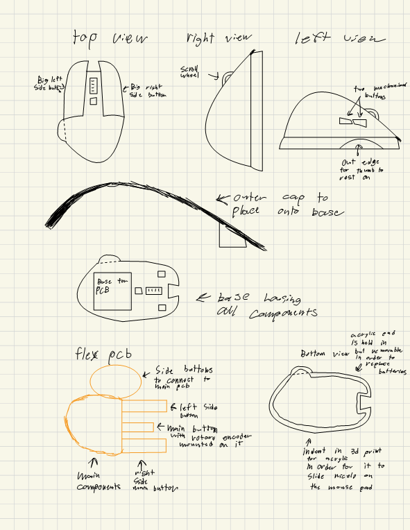
Bluetooth Computer Mouse
MCU ESP-32 Nano DESIGN EasyEDA - for inside of the mouse I will attempt to make a flex pcb in order to fit the inside and reach all of the buttons within the mouse Fusion – to create the body and encasement for the pcb and buttons Acrylic – for the bottom of the mouse in with the correct shape and curves in order to slide easier on the mouse pad COMMUNICATION I will be using Bluetooth to communicate between a USB and the mouse in order to control it on the screen MECHANICAL I will be using PBNOs as the buttons along with a rotary encoder for the scroll wheel for the mechanical feel and scrolling. |
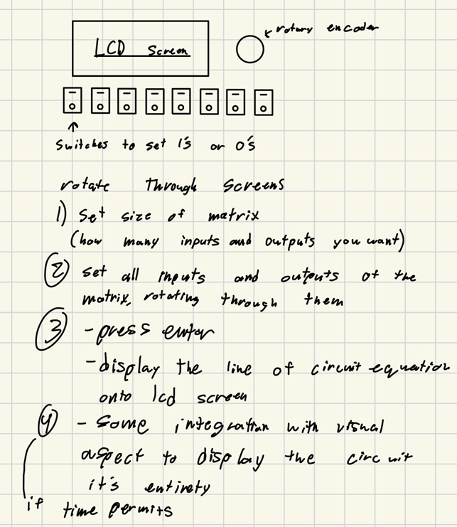
Karnaugh Mapping Device
DESCRIPTION The Karnaugh Mapping Device takes a matrix of ones and zeros as input, processes it, and generates a simplified Boolean equation using NOT, AND, NAND, OR, NOR, and XOR gates. It automates the Karnaugh mapping process to help with logic circuit design. The device uses an LCD screen to display results and communicates via serial connection. |
? DESCRIPTION MCU HARDWARE SOFTWARE DESIGN MECHANICAL
|
Harsha G.
(Computer?) |
Bluetooth Device Finder
MCU ESP-32 BLE Nano DESIGN The final product will be housed inside a Fusion-built case, containing an EasyEDA made pcb. COMMUNICATION I2C communication (for OLED) and Bluetooth LE (to connect between Nano ESP32 and nearby Bluetooth devices) will both be incorporated. MECHANICAL N/A |
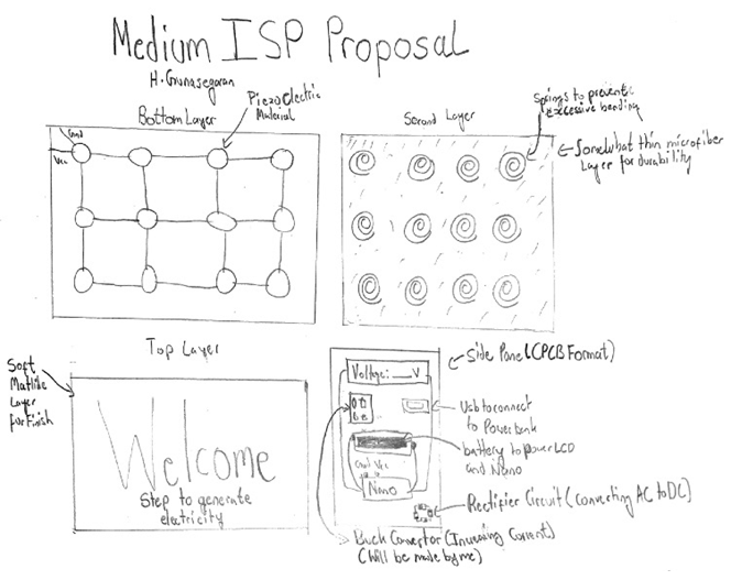
Footstep-Driven Power Generator
MCU 328P HARDWARE SOFTWARE C DESIGN PCB & Case COMMUNICATION I2C MECHANICAL None (?) |
? DESCRIPTION MCU HARDWARE SOFTWARE DESIGN MECHANICAL
|
Chance H.
(Mechanical?) |
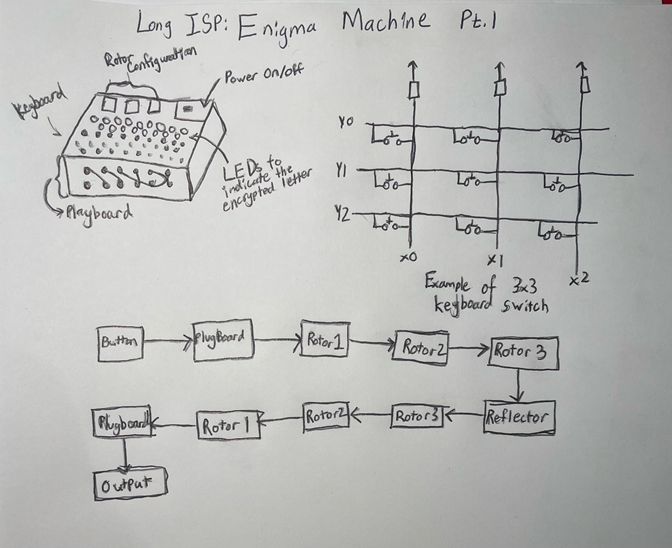
Enigma Machine Pt.1
MCU Raspberry Pico Wireless DESIGN Fusion360 will be used for the overall case design, if time permits I may try to create a more permanent metal case as I predict that a single 3d printed Enigma Machine case would use up a large amount of filament. The PCB will be designed through EasyEDA COMMUNICATION The device will use Serial Communication for the button inputs and the plug board. MECHANICAL N/A??? |
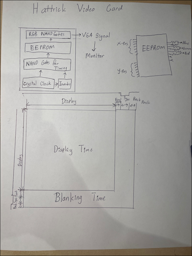
ACES' Video Card
MCU None HARDWARE The device will use a series of inverters and NAND gates to create the timing for the display which will allow the EEPROM to know where it is on the monitor. I will also be using a PLL circuit to alter the frequency of the crystal oscillator to match the requirements for my intended resolution. Currently I do not have any plans of using a MCU. SOFTWARE C/Python. Libraries: Python PIL Library I will be using the PIL library in python to break down my image into the hex-values for each of the individual pixels and then I will use these values to program my EEPROM in Arduino to display the image DESIGN I will use fusion360 to design a 3D case for the video Card and EEPROM Programmer and use the JLCPCB software to design the custom keyboard for the card and the EEPROM Programmer COMMUNICATION MECHANICAL |
? DESCRIPTION MCU HARDWARE SOFTWARE DESIGN MECHANICAL
|
Rohan J.
(Computer?) |
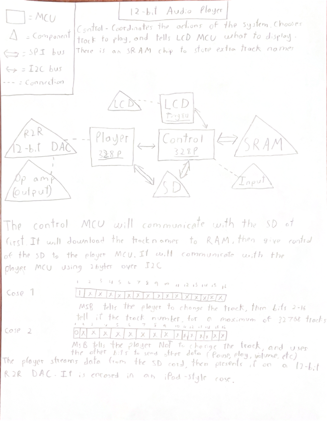
12-Bit Audio Player
MCU 328p/84 DESIGN Will be in a case designed in Fusion360. The case will (hopefully) somewhat resemble an early iPod (perhaps a little bit thicker). The whole circuit will be on 1 PCB, with as many surface mount parts as possible (to reduce their footprint) and it will be baked in the ACES reflow oven COMMUNICATION Since there are multiple MCUs, there are communication busses between them, as well as other components. Firstly, the main “control” MCU has an I2C bus that it uses to communicate with the “player” and “LCD” MCU. It uses 2 bytes to communicate with the “player” MCU (see drawing). It also has an 8-bit SPI bus to access an additional SRAM chip, and a regular SPI bus to be able to read from an SD card. The “player” MCU has an SPI bus to read from the SD card. The way that the device works: when it’s powered on, it “boots” up. During this time, the main MCU downloads the name of every track into RAM, and assigns it a number (based on location on SD). Then, it gives up control of the SD to the player MCU. At this point, the device is booted. When the user selects a track, the control MCU sends the number over I2C (along with other data) which causes the player to play back that track, streaming data from the card. Having 3 separate MCUs allows the user to scroll through the device while audio is playing. MECHANICAL N/A |
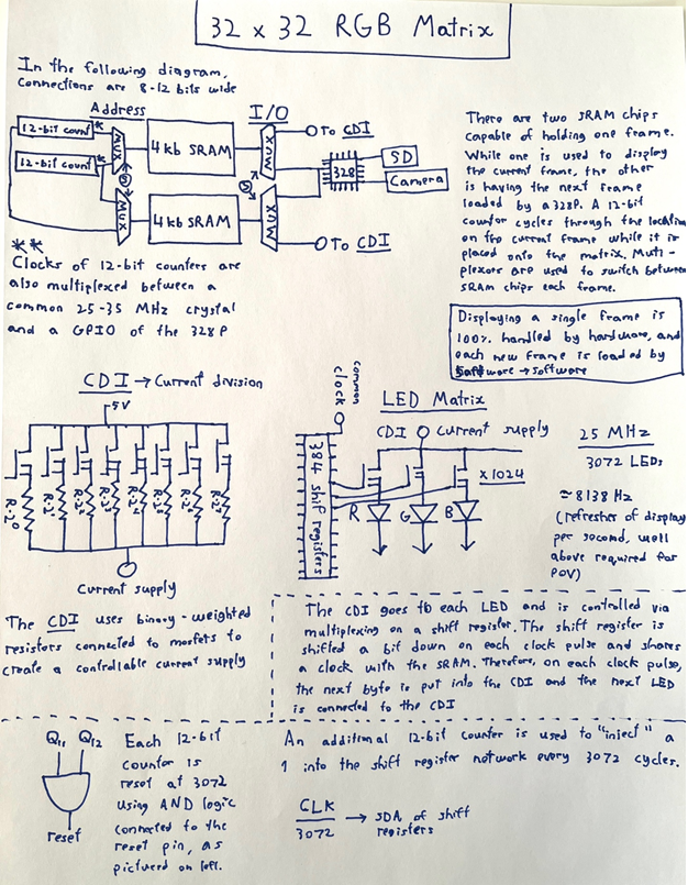
32 by 32 RGB Matrix
MCU 328P HARDWARE The project is mostly hardware-based. There will be 384 shift registers, just over 3072 MOSFETS, and several 12-bit synchronous counters. The 328P is simply used to update the frame buffer (SRAM). SOFTWARE Libraries: SD, potentially Camera as well Libraries are not required for the vast majority of the project. It will likely be required to access the SD card, and the camera as well depending on the camera used. DESIGN The circuit will be built on a PCB. The entire design will never be made on a breadboard due to its complexity, though the design is relatively modular and a scaled down version will be built on breadboard for testing purposes. Additionally, the design will be housed in a 3d printed enclosure where only the actual matrix is visible (not the entire board and chips). COMMUNICATION N/A MECHANICAL N/A |
? DESCRIPTION MCU HARDWARE SOFTWARE DESIGN MECHANICAL
|
Jett K.
(Mechanical?) |
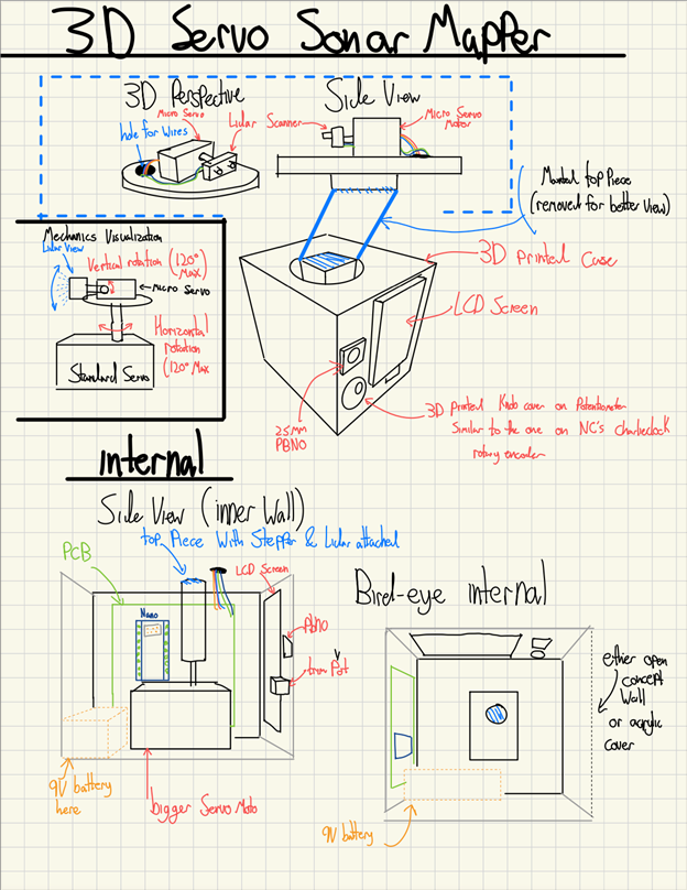
3D Servo Sonar Mapper
At the same time, the sensor will be rotating horizontally, then vertically via servo motors, and will map out a complete picture of a 2D window of your desired size. This 2D window will then be displayed on a 1.8" LCD tft display, where the further the distance, the darker the color will be on the screen. Before the mapping process begins, it will ask you what scale of distance you want the colour spectrum to vary to. This is done so that if you know that the objects in the frame you plan on measuring has very similar distances to one other, you might want to make the contrast higher to see distance differences better. MCU 328p DESIGN It will all be encased in a final fusion case, and will have an easy EDA PCB circuit board. COMMUNICATION SPI MECHANICAL This project will use 2 Servor Motors, a Servo - Hitec HS-425BB (Standard Size) (as they will require more torque and will also have to support a LIDAR + another servo. This brings me to the second servo motor, a Servo - Hitec HS-85MG (Micro Size). |
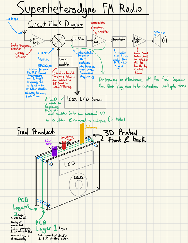
Superheterodyne FM Radio
MCU None HARDWARE If there is a display I will still try to avoid a microcontroller. If necessary however, I may have to use an 85 ( I will try to avoid this as much as possible). SOFTWARE N/A DESIGN PCB & Case COMMUNICATION Radio Frequency MECHANICAL Antenna & Speaker |
? DESCRIPTION MCU HARDWARE SOFTWARE DESIGN MECHANICAL
|
Triyan K.
(Aerospace) |
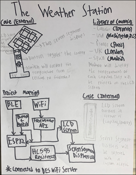
The Weather Station
The Weather Station is a device that will leverage the ESP32’s WiFi and Bluetooth Low Energy (BLE) capabilities to display the current temperature on two seven-segment displays. As I connect the ESP32 to the internet, it can update the temperature in real-time; this will be done by feeding the Nano with data from an application programming interface (API) called Free Weather API. The data will be outputted in JSON and XML and I will convert this into data that Arduino can handle. I will utilize JSON as it is a more friendly data type in Arduino, there are dedicated libraries for it while XML doesn’t. Additionally, because the API keeps track of the weather across places worldwide, I will create a library of the capitals of countries such as Canada, US, UK, France, and Spain. that the user can toggle to see the temperature. This toggling will be enabled by pressing a button. Moreover, there will be an LCD screen wired to the ESP32 to signal to the user what region’s/country’s temperature is being displayed. To shift out values from the MCU to the seven-segment display, I will use two 595 shift registers, one for each seven-segment display. The MCU’s BLE feature will allow me to broadcast the temperature of different countries in the DES to other devices. Finally, there will be a switch that convert the temperature on the seven segment displays from Fahrenheit to Celsius and vice versa. The final product will resemble a real-life weather station with the seven segment displays protruding from the front with an acrylic and the LCD screen with one switch (temperature) and one button (country). MCU ESP-32 Nano (BLE)DESIGN First, I will use Fusion 360 to design the case which will resemble a real-life weather station. The temperature will be displayed in a case with a long stand. Next, I will use EasyEDA to create the PCB which will be embedded in my case. Since it’s powered by 5 V, there will be an opening in the case for the power supply. A voltage regulator of 5 V will be on my PCB to facilitate this. Finally, I intend on making an acrylic (with my name and ACES logo) that’s placed on top of my seven-segment display for a cleaner presentation. COMMUNICATION I will use the ESP32’s Wi-Fi and Bluetooth Low Energy (BLE) features for my project. By connecting to a Wi-Fi network, I can hook up my ESP32 to an online weather API such as Free Weather API which will update the temperature in real-time via an LCD screen. The BLE is an additional feature that will allow me to connect to other devices in the DES and broadcast the temperature. Additionally, the BLE system will allow the device to update settings and function properly without any human input. MECHANICAL N/A |
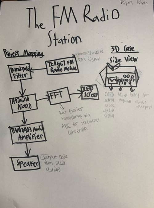
FM Radio
MCU 328P HARDWARE ? SOFTWARE Libraries: TEA5767.h, Wire.h, Arduino FFT DESIGN I’ll use JLCPCB’s manufacturing services to produce my PCB, which will be designed on EasyEDA. I will then 3D print a rectangular case for my PCB on Fusion. The entire PCB will fit in the case with only the speaker and OLED screen visible, so that the audio can easily be heard and that the radio station can be seen. There will also be a potentiometer protruding out so that the radio station can conveniently be changed. COMMUNICATION This project makes use of I2C to connect the TEA5767 FM Tuner to the Arduino. The FM Tuner uses RF to transmit/receive the FM signals. MECHANICAL N/A |
? DESCRIPTION MCU HARDWARE SOFTWARE DESIGN MECHANICAL
|
Lucas Q-T.
(Mechatronics?) |
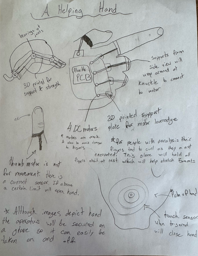
A Helping Hand
MCU 328p DESIGN Fusion 360, EasyEDA, JLC PCB, 3D Printing COMMUNICATION None MECHANICAL 4 DC motors 1 torque sensor Touch sensor Current sensor |
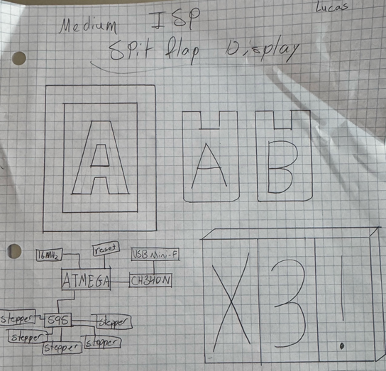
The Split Flap Display
MCU 328p HARDWARE Will use shift registers to control each stepper motor if the ATMEGA does not have enough pins. Additionally, will use a ATMEGA328P and try to make it work since mine didn’t in the long ISP SOFTWARE Will use an ATMEGA to control each motor using AVR assembly DESIGN Fusion 360 for each display box that will hold each symbol and the stepper motor. JLCPCB and Easy EDA for the PCB that will hold the ATMEGA which will control each stepper motor. COMMUNICATION N/A MECHANICAL Stepper |
? DESCRIPTION MCU HARDWARE SOFTWARE DESIGN MECHANICAL
|
| Goran S. (Aerospace?) |
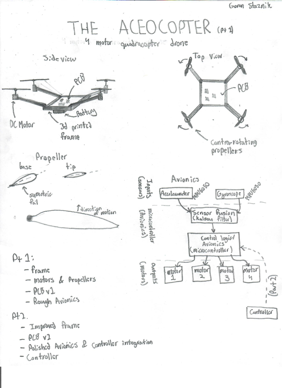
ACEOCOPTER Pt.1
MCU 328p DESIGN I plan on using onshape for the propellers, as it is easier to make airfoils in it, and fusion for the body. The avionics will sit in a central area with the battery which will be slightly lower than the propellers (for center of gravity). COMMUNICATION None. (Part 2) MECHANICAL DC Motor × 4 |
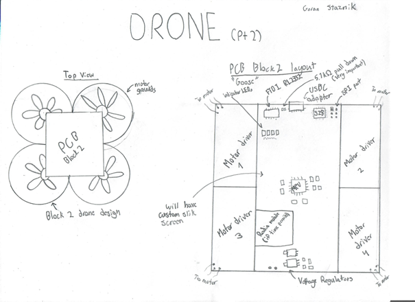
ACEOCOPTER Pt. 2
DESCRIPTION This is the second part of the drone project which focuses on the avionics allowing the drone to hover. If time permits, I would like to add a controller which would communicate through radio to command movements. |
? DESCRIPTION MCU HARDWARE SOFTWARE DESIGN MECHANICAL
|
Atticus T.
(Mechanical?) |
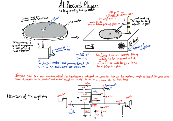
AT Record Player
MCU 328p DESIGN For design, I plan on creating a box that holds all of the wires and internal components such as the various PCBs that I will design in EasyEDA. I also plan on 3D printing quite a few components such as the parts that are attached to the turn table all created in Fusion360 COMMUNICATION Serial Communication may be used in the creation of this project – I2C can also be incorporated for things such as a motor controller as it is especially useful if I am planning on working with multiple sensors or control devices. MECHANICAL In order for the turntable to spin, the best motor that I have come across and will work the best will be a stepper motor. Although being a stepper motor, since the turntable is moving at such a fast rate, the result is going to act much like that of a sine wave therefore it will be the easiest to work with as it is also easily controllable. |
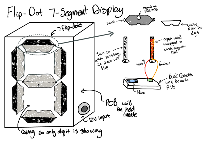
Flip-Dot 7-Segment Display
MCU 328p HARDWARE Will use a Nano most likely as the project mainly focuses on the concepts however I may upgrade this if I have enough time SOFTWARE Arduino C (no libraries) DESIGN The Design is one of the more complicated aspects as I have to not only design a case that encloses the PCB and it set up in a way that when a digit is shown, it is legible, but each flip-dot needs to be individually printed and designed. This will be done using Fusion360. The PCBs will be created on EasyEDA as well. COMMUNICATION N/A MECHANICAL N/A |
? DESCRIPTION MCU HARDWARE SOFTWARE DESIGN MECHANICAL
|
Max Z.
(Electrical?) |
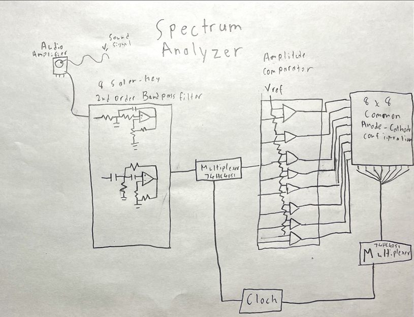
Spectrum Analyzer
MCU None DESIGNAn Easyeda designed PCB will be sent to JLCPCB for order. a 3D encasement to make the 8x8 LED configuration look visually appealing. COMMUNICATION N/A MECHANICAL N/A |
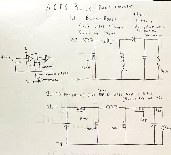
ACES Buck-Boost Converter
MCU None HARDWARE Uses passive Resistor, Capacitor and Inductor components. PWM signal coming from a triangular Op-Amp PWM Generator and TL494. IRLZ44N MOSFET SOFTWARE None DESIGN JLCPCB(Through Hole and SMD) and Fusion360 Case COMMUNICATION None MECHANICAL None |
? DESCRIPTION MCU HARDWARE SOFTWARE DESIGN MECHANICAL
|
