| 2019-2020 ICS4U Tasks |
![]() [Postponed] ATtiny85 SMD. This project is designed to provide you with increased SMD soldering exposure, flashing experience from AS7, and AVR assembly programming confidence.
[Postponed] ATtiny85 SMD. This project is designed to provide you with increased SMD soldering exposure, flashing experience from AS7, and AVR assembly programming confidence.
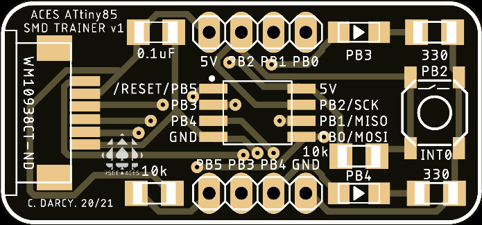
The adjacent breadboard-friendly SMD PCB was developed in early March 2020, specifically to address the issues arising from the challenge of the Medium ISP SMD expectations. In retrospect, we should have undertaken this project in early January, and that's on me. EAGLE files for this device can be obtained from our ACES Optimization Github Repository.
Task.
ATTiny85_SMD and develop UNIQUE-TO-YOU AVR Assembly code to exercise and maximize the PCB's on-board assets and off-board breadboard capabilities. 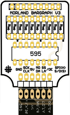
![]() Shiftout. For your next AVR Assembly project
submission you will cover very familiar ground and take it to its deepest level yet. With each new, measured, and highly-focused task, your skill and confidence will (should!) grow.
Shiftout. For your next AVR Assembly project
submission you will cover very familiar ground and take it to its deepest level yet. With each new, measured, and highly-focused task, your skill and confidence will (should!) grow.
The composite image to the right reveals how the DDB's pin arrangement was designed to integrate perfectly with the MBv3. Click to enlarge.
Task.
Using the knowledge and skill accumulated over the past two years, especially the register-level C code discussed in our Meets this week, develop the AVR assembly code shiftout.asm (or shiftout.S) to directly manipulate the PORTA and PORTB bits (using the sbi and cbi instructions) in an orchestrated manner, to have the Morland Bargraph present an 8-bit binary constant on the lower 8 LEDs of your Morland Bargraph v3. (Note. If you do not have an MBv3 with you at home, simply wire up a '595 to the DDP and 8 LEDs in a similar manner with respect to the 84's PORT bits)
For this submission, I'm limiting it to the creation of a well-structured, planned, and strategically-shot and presented 3:00 video (maximum) that encompasses as many of the video presentation skills we've discussed over the years. The result should leave the viewer with crystal clear clarity of the concepts in play and a solid sense of how your code works. (Hint: This will take serious planning and organization). Finally, think of this in the style of a video resumé you may be asked for in the future by a potential employer.
You are to attach your doucmented code to your email to handin as well.
![]()
![]() Bicolor Byte. For your first formal AVR Assembly project
submission you are asked exploit use of the code functions we developed last class to interpret a byte as an (MSBFIRST) colour sequence on a bicolor LED. The code is to be Green for 1 and Red for 0. Each colour is to be held for 1 second, with no delay or gap in between. At the end of the 8 bit/colour sequence, turn the LED off for 3 seconds before repeating, indefinitely.
Bicolor Byte. For your first formal AVR Assembly project
submission you are asked exploit use of the code functions we developed last class to interpret a byte as an (MSBFIRST) colour sequence on a bicolor LED. The code is to be Green for 1 and Red for 0. Each colour is to be held for 1 second, with no delay or gap in between. At the end of the 8 bit/colour sequence, turn the LED off for 3 seconds before repeating, indefinitely.
Example. If the program 'played' the byte value 0xAA, the colour sequence would appear as in the animated gif to the right: GRGRGRGROOO where G-green, R-red, and O-off.
Note. Documentation and artfully-crafted statement comment writing are skills unto themselves. You will be held to high account on this point in university, so accept it. You can prepare for this eventuality by presenting your code, masterfully, in your DER next weekend.
![]() Dolgin Development Board Legacy Shield
Dolgin Development Board Legacy Shield
Task.

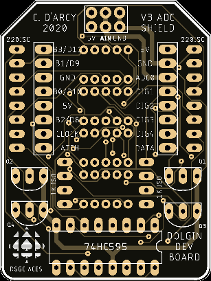
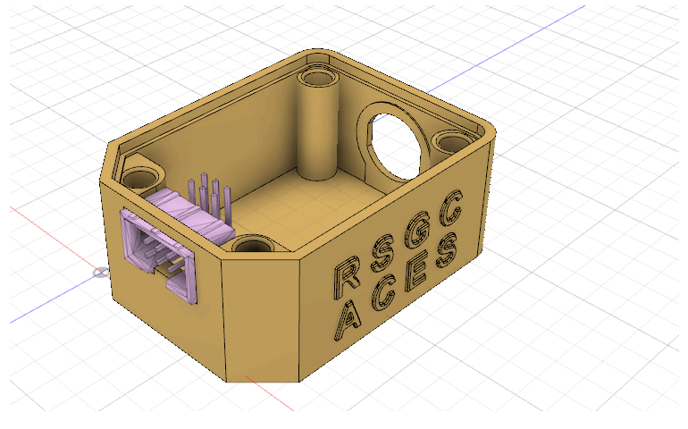
![]() Dolgin Development Board Shields. Modelling the Arduino's 'Shield' concept for the Dolgin Development Board, I designed two (THT) shields that can be assembled, inserted into the female headers and programmed. These appear below.
Dolgin Development Board Shields. Modelling the Arduino's 'Shield' concept for the Dolgin Development Board, I designed two (THT) shields that can be assembled, inserted into the female headers and programmed. These appear below.
Soldering Considerations
Task.
Intersection Shield |
Analog-to-Digital Conversion (ADC) Shield |
|---|---|
 |
 |
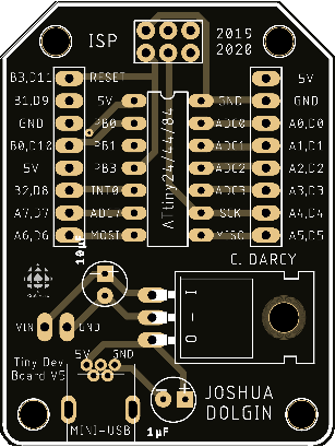
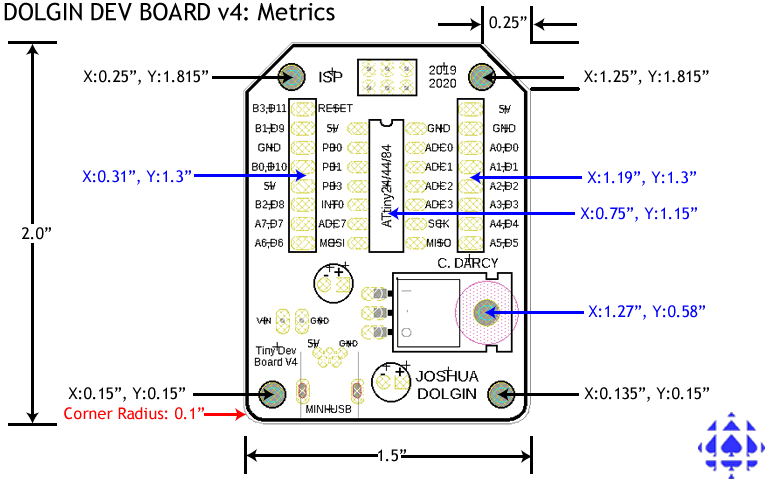
![]() Dolgin Development Board. J. Dolgin (ACES' 20) continued the ACES commitment to excellence by developing a compact AVR development board based on the ATtiny24/44/84 MCU suite for his Grade 11 legacy PCB project. This board will serve as a substantial contributor to the exploration of advanced MCU hardware, software, and design pursuits in this year's Senior ICS4U curriculum.
Dolgin Development Board. J. Dolgin (ACES' 20) continued the ACES commitment to excellence by developing a compact AVR development board based on the ATtiny24/44/84 MCU suite for his Grade 11 legacy PCB project. This board will serve as a substantial contributor to the exploration of advanced MCU hardware, software, and design pursuits in this year's Senior ICS4U curriculum.
Design files for this device (.sch, .brd, and .f3d) can be downloaded for personal use from,
https://github.com/rsgcaces/AVROptimization/tree/master/DolginDevelopmentBoard
Task.
 Project 3.2. CharlieStick. The software side of the final two terms of your ACES experience is invested in the exploration of the native language of the AVR family of microcontrollers, simply referred to as AVR Assembly. This justifies the alternate name for our course, AVR Optimization, for it is only through coding in the native language of the microcontroller can the most efficient performance be realized. In preparation for that journey, we will first investigate a few advanced Arduino C software techniques that involve the use of register-level instructions (iom328p.h). The first of these engages a technique known as Charlieplexing.
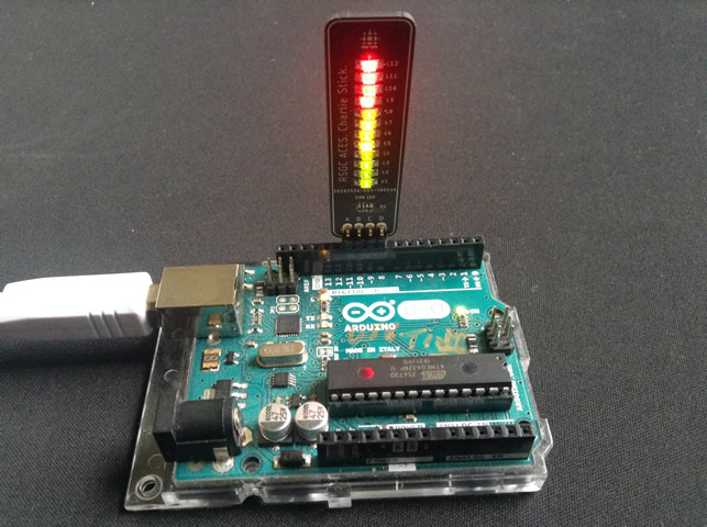
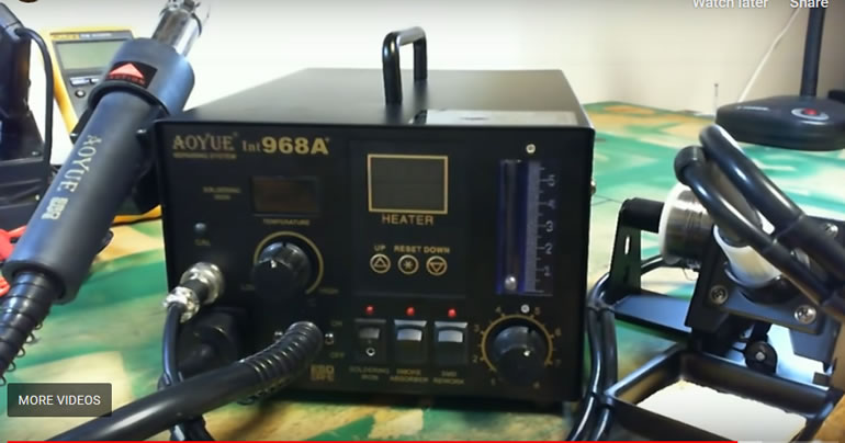
![]() 3.2.1. (30 min. assembly time) To further your SMT soldering skiils amongst other goals, a custom-designed ACES' PCB appliance consisting of 12 SMT 1206 LEDs, 1 SMT 1206 220 Ω Resister Array and a 1×4 pin header has been developed for use with this project. A photo of an assembled and fully active CharlieStick appliance appears to the right. For the first part of this project you are asked to find time this week to assemble your PCB using one of our two Auyoe 968A Rework stations. When completely soldered, bring it to me and I'll test it in my Arduino platform on either Monday, Wednesday, or Friday. I'll add your initials and return it to you for your DER submission on Saturday October 26.
3.2.1. (30 min. assembly time) To further your SMT soldering skiils amongst other goals, a custom-designed ACES' PCB appliance consisting of 12 SMT 1206 LEDs, 1 SMT 1206 220 Ω Resister Array and a 1×4 pin header has been developed for use with this project. A photo of an assembled and fully active CharlieStick appliance appears to the right. For the first part of this project you are asked to find time this week to assemble your PCB using one of our two Auyoe 968A Rework stations. When completely soldered, bring it to me and I'll test it in my Arduino platform on either Monday, Wednesday, or Friday. I'll add your initials and return it to you for your DER submission on Saturday October 26.
Task.
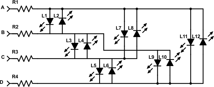
 You are to surface mount solder 4 Green, 4 Yellow and 4 Red (bottom to top) using your preferred method, solder pen, air or bake (if Eric and Simon do their job!)
![]() 3.2.2. See here...
3.2.2. See here...
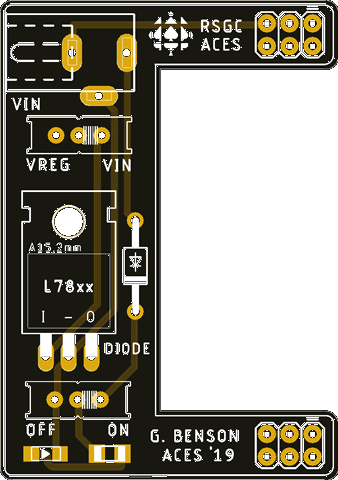
![]() Project 3.1. GB Machine. The greatest challenge (and privilege) for ACES is to influence the direction of our program. Through your imagination and skill you are expected to contribute to the enhancement of our mutual creativity, tool set, and assets. G. Benson (ACES' 19) fulfilled this opportunity/commitment through his enhancement of the indispensable PB Machine (P. Bagga, ACES '17). Beginning in the Fall of 2019, Grade 11 and 12 ACES will be expected to solder up their own GB machine and put it to good use in the pursuit of their own prototypes.
Project 3.1. GB Machine. The greatest challenge (and privilege) for ACES is to influence the direction of our program. Through your imagination and skill you are expected to contribute to the enhancement of our mutual creativity, tool set, and assets. G. Benson (ACES' 19) fulfilled this opportunity/commitment through his enhancement of the indispensable PB Machine (P. Bagga, ACES '17). Beginning in the Fall of 2019, Grade 11 and 12 ACES will be expected to solder up their own GB machine and put it to good use in the pursuit of their own prototypes.
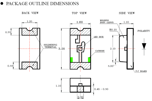
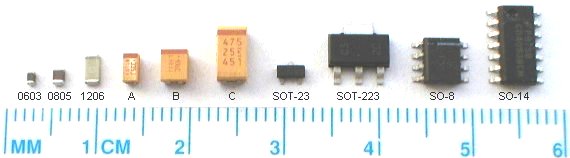
Your experience with electric circuits has been largely limited to components that use through-hole technology (THT). To round out your proficiency with all components, your next few projects will require the use of devices that use surface-mount technology (SMT). As the graphic reveals, the smallest size that is reasonable for hand-soldering techniques is the 1206 family, so this is what we carry in the DES inventory.
GB Machine |
1206 LED Package |
|---|---|
 |
 |
Task.