 Few microcontroller applications are as pervasive and practical and as Communication. Our TEJ3M curriculum introduces ACES to a subset of (wired and wireless) Arduino-compatible Communication Protocols (Bluetooth and Wi-Fi are left to you to explore at home). Another communication protocol you may wish to explore involves the transmission of data through light using simple LEDs. Ethan. McAuliffe (ACES '18, McMaster '22) made it the focus of his brilliant (MacGyver-inspired) Medium ISP (the Photophone). Ethan documented his project on his personal blog. Unfortunately, the original video of the project was posted under the College's account and is lost (like so many other irreplaceable student gems). Alex Araujo (ACES '27) used fibre optic cable in support of his Grade 11 Long ISP (
 Morse Code Decoder).
Bluetooth (Wireless UART) with the HC-05 Transceiver
 We finish up our ICS3U look at Arduino-Compatible Communication protocols by returning to where we began weeks ago, with the Arduino's UART. However, this time, we're exploiting it wirelessly, under the Bluetooth (2.4GHz radio) banner.
Given the complexity of the pairing sequence of the Bluetooth protocol this introduction will limit itself to Arduino⇆Arduino communication. Motivated students are encouraged to explore Arduino⇆Laptop and Arduino⇆Android Phone pairings.
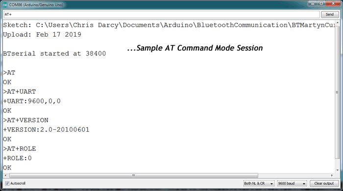
As is the custom of the Serial UART protocol between two devices, the roles of master and slave must be established. These roles, together with a few other parameters, must be written into the RAM of the devices prior to the pairing. This is accomplished by entering AT COMMAND Mode and entering the required values. AT Command References appear below.
Although there are a few blogs out there with plenty of detailed backround information, I found this terrific video got right to the point of successfully pairing up two HC-05s.
How to Pair HC-05 Bluetooth Modules
 LED Flashing Patterns
- Rapid Blinking? Standard pairing Mode (looking for another HC-05 to pair with...)
- Long Slow Blinking? AT Command Mode
- Slow Blnking in Sets? Paired!
Github: BT Confirmation sketches discussed in class
Additional References
IC Datasheet and AT Command Manual: EGBT-045MS/EGBT-046S
AT Command Set
Martyn Currey Tutorials
Self-Reflection (2019 02 18)
 Bluetooth-capable devices are, generally, expensive.
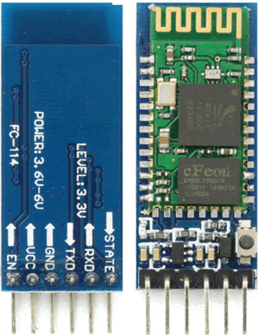
 - The HC-05 offers a $10. hobby-level, bluetooth experience. It's a THT breakout board that carries the BC417 (single chip) Bluetooth core IC, an onboard 1MB, non-volatile Flash RAM IC (such as the EN29LV800C with the gold check mark), a 3.3V regulator and a few supporting passives.
- There's plenty of misinformation out there so stick to the reputable sites to avoid compromising your devices.
- The difference between the HC-05 (6-pin) and HC-06 (4-pin), taken from in Martyn Currey's First Look tutorial, is, "The HC-05 can be a master or slave. The HC-06 is a slave only. This means the HC-05 can initiate a connection to another device and the HC-06 can only accept a connection from another device". We'll stick with the HC-05 (EGBT-045MS), exclusively, to simplify our discussion.
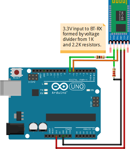
- The HC-05 is really a 3.3V device. Most of its pins are 5V tolerant but the Arduino TX → BT Rx line MUST be 3.3V. See the Fritzing diagram.
- The device has two modes: (AT) Command Mode and Communication Mode. Use the former to set the parameters of the device and the latter for the actual communication.
- The HC-05 firmware can be programmed by users in AT Command Mode to set the role of the device to either Master (AT+ROLE=0) or Slave (AT+ROLE=1)
- The device is very much like a wireless UART so, once you establish the Master/Slave roles between two transceivers it 'should be' straightforward enough.
- All-in-all, hobby-level Bluetooth is not a casual option. You may need to wrestle with poorly-documented hardware and firmware.
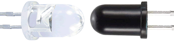
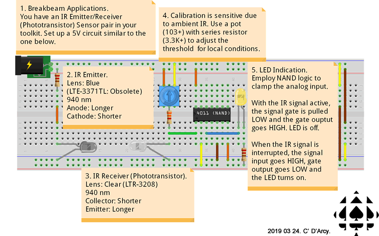
IR Sensing with 940nm 5mm Emitter/PhotoDiode Matched Pair
For the first of a few IR investigations you are asked to examine the use of the 5mm LED matched Emitter/Photodiode pair (940 nm) provided in your Session 6 Supplementary Parts kit. These components can be employed to detect interruptions and tuned to detect the proximity of an object.
 From personal experience I caution you to be aware of the inconsistency of the lens colours and vocabulary surrounding these devices, resulting on blogs and videos that are confusing, misleading and, occasionally, incorrect. This problem is so acute I hestiate recommending any links as I haven't found a single one that accurately employs correct interpretation. The root of the problem, in my opinion, is two-fold. First 3 mm and 5 mm LEDs of any wavelegnth, typically do not have part numbers silk screened on them so datasheets are not accessible. Secondly, there are not enough DIYers in the world willing to spend the time to explain the correct fundamentals to other DIYers in a format and language they understand.
The photodiode can also be called the detector. However, I would hesitate calling the photodiode a receiver as that term should be reserved for the device in part two of this investigation, consisting of more complex internal componentry.
Task 1. Break beam (Basic Digital; No Code/MCU)
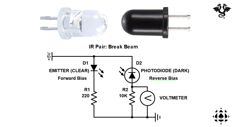 For this initial task you are simply going to monitor the voltage falling and rising as a result of blocking the IR signal between the emitter (clear) and the photodiode (dark).
- Good reference video for connections: IR Receiver/Transmitter Pair.
- Breadboard the circuit to the right and monitor the voltage at the test point (TP) shown.
- Tying this TP to either an External Interrupt pin of your MCU or reading it from an analog input pin could provide the basis for monitoring the angular speed of your DC hobbly motor.
Task 2. Proximity Sensing (Analog; MCU)
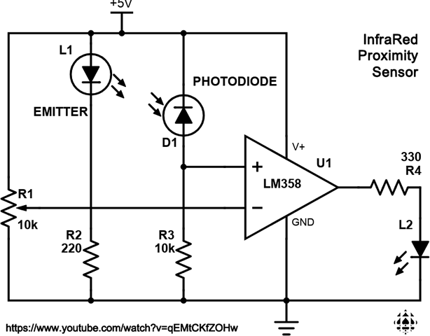 Watch this illuminating video explanation of the circuit you are asked to create IR Proximity Sensor.
Question. If you're like me, you might have wondered why the IR Photodiode Detecter (our black LED) was inserted backwards! (ie reverse bias) Google: Photodiode reverse bias to find out why.- I have prepared a schematic of the same circuit to the right (click to enlarge) that I would ask that you assemble a prototype from, using the components in your kit. (LM358 OpAmp Datasheet)
- Explore the effects of changing the voltage level on the inverting input (by turning the pot) on the range of distance sensing.
- Optional. (for the inspired or bored; either will do:) This 'detector' circuit signals when an object traverses a certain distance threshold. I'm thinking it shouldn't be too difficult to intercept the detector's voltage output with an
analogRead() to have the Arduino translate the reading into a numerical distance and either report it to Serial Monitor or throw it up on an LCD.
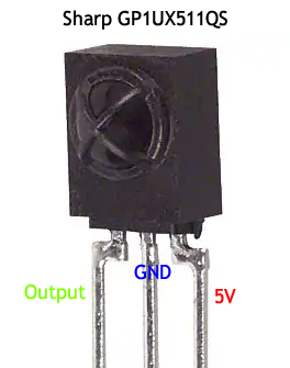
IR Data Communication with GP1UX511QS (35m)
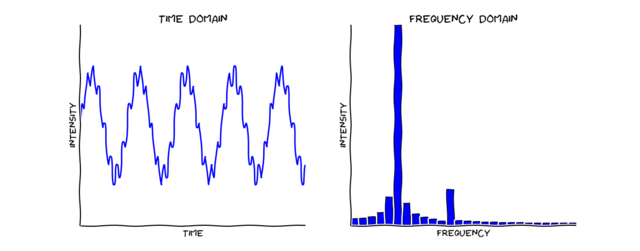
The graph (below, left) is of a data signal modulated upon a carrier wave. Demodulation can separate the carrier frequency from the data (below, right) using mathematics (FFT).
Source: Adafruit Learning- FFT Fun with Fourier Transforms
 SBProjects: IR Control Theory (A Must Read)
Ken Shirriff:
- Arduino as Universal Remote
- Multi-Protocol IR Library For Arduino
- IRremote Library Code
Sparkfun: IR Communication (with Supporting Video Tutorial)
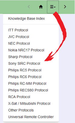
The majority of the IR protocols from NEC, Philips, Sharp, etc. center on 38kHz, far enough outside the frequency band of ambient IR sources like the sun, flames and other common light sources to avoid signal noise issues. Sony's SIRC protocol differs and is centered on 40kHz. For a project you may wish to pursue simply ask me for an IR Receiver for either frequency.
Task.
- Breadboard and test this simple 5V beambreaker circuit.
- Install the GP1UX511QS IR Detection device, along with a bicolor LED as appliances in your UNO as shown below,
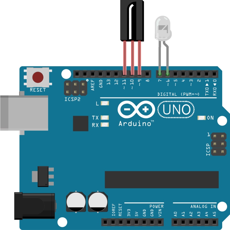
- Pay close attention to our collective review of the sketch code contained in the handout, IRLEDControl.docx.
- Once Shirriff's IRremote library in installed, open the sketch IRLEDControl and upload it to your UNO.
- Open the Serial Monitor and start pressing buttons on your remote. Look for consistent patterns between the data being displayed and the results data structure.
- With the knowledge gleaned from the previous step, explore make modifications such as swapping the Bicolor LED with an RGB LED.
Possible Project Considerations:
RF: Radio Frequency Communication (with Nordic's nRF24L01)
 AVR Foundations: pp. 85-88
Web Reference: Arduino Wireless Communication
Kevin Darrah: nRF24L01+ Arduino Communication
Video Review: nRF24L01+ Options
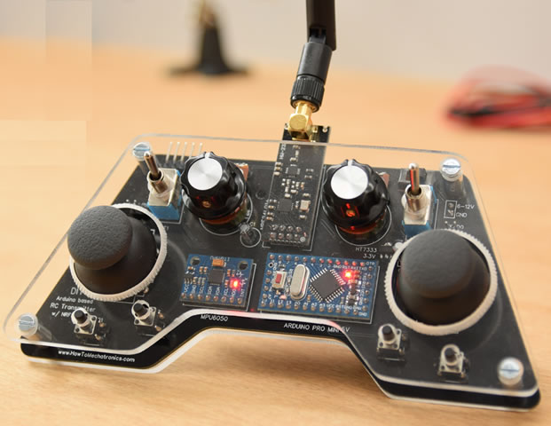
Inspiring Project: DIY Arduino RC Transmitter
So here's what I've learned from my research and preparation for this introduction to RF (presented in an order that should make sense)
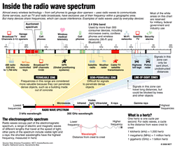
 The unlicensed radio frequency band open to the Industrial, Scientific and Medical (ISM) Communities operates within the 2.400GHz to 2.525GHz range of the electromagnetic spectrum. (This 4G technology is about to be supplanted by 5G in which the next generation of devices will exploit the 6GHz frequency band)
- For the orderly and reliable transmission of data, a separation of 0.001GHz is required, leading to 126 possible avenues (referred to as channels).
- Since cell phones, bluetooth devices, near field communication (NFC) devices, and wireless computer networks (WiFi) all use the ISM frequencies this frequency band can get very crowded.
- For a few dollars Nordic's nRF24L01+ Transceiver offers Arduino users simple communication access to ISM devices over a range as high as 800m, consuming lower current than a typical LED (12mA), selectable data rates up to 10Mbps, and a STRICT VCC requirement of 3.3V, with other pins being 5V tolerant.
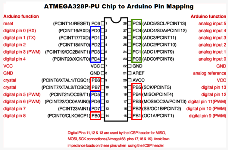
- The nRF24L01 communicates with your Arduino through the SPI protocol (MOSI-11, MISO-12, SCK-13). The complete table of the 20 pin functions appears on page 11 of the datasheet.
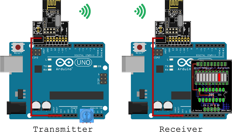
- An ACES Appliance PCB Breakout board has been designed to facilitate efficient insertion of the nRF24L01+ directly into your Arduino's PORTB. The only wire required connects the appliance to the 3.3V supply pin on the other side of the Arduino as shown below.
 I've written a matched pair of CHANNEL numbers on the backs of the breakout boards. Insert your nRF Appliance into your Arduino and find your partner. Designate one partner as the Transmitter (Tx) and place a trim pot in PC0 to PC2 as shown below. The other platform is the Receiver (Rx) and should have a Morland Bargraph inserted in PC0-PC4 as shown.
- For the code aspect of this project you will rely on the well established RF24 library with the documentation found at https://tmrh20.github.io/RF24/classRF24.html
- Transmitter: Create the Arduino Project TxTest and replace the template code with this sketch code.
- Receiver: Create the Arduino Project RxTest and replace the template code with this sketch code.
- Both the Transmitter and Receiver sketches will edit the CHANNEL definition to match the number on the back of their appliance.
- Upload the sketches to their respective platforms and confirm that analog readings from the transmitter is sent and received across the room and displayed on the receiver's bargraph.
I2C: Inter-Integrated Communication
 AVR Foundations: pp. 90-93
Reference: Arduino Wire Library
Gammon: Two-Wire Peripheral Interface
Video Tutorial Example: TC74 (Start at 54s)
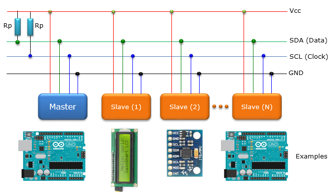
Whereas the SPI protocol requires an extra SS pin for every additional slave device, the I2C protocol only requires two pins (in total) to communicate to up to 128 devices. Imagine an 8-pin ATtiny85 controlling up to 128 other devices! One pin is a clock line for synchronous support and the other pin is the data line. These two pins are Serial Clock (SCL) and Serial Data (SDA), respectively. Conveniently, the pins are broken out on the UNO on both sides of the Arduino. SCL and SDA share the Analog A5 and A4 pins and the two pins closest to the Reset button if the analog pins are required for other purposes.
Philips Semiconductor (now NXP of the Netherlands) developed the technology in 1982. Since I2C is a trademark, manufacturers of devices must pay a license fee to use the term. Microchip (formerly ATMEL) and other manufacturers get around the fee by calling their devices TWI (Two-Wire Interface) but they're 100% compatible.
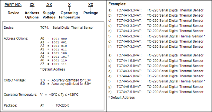
The key to this highly-leveraged, efficient strategy is that the I2C bus acts like a street with devices having addresses on that street. Addresses are set by the manufacturer and impressed within the device. Let's focus on one such I2C/TWI device: The TC74 Digital Thermal Sensor. Open the TC74 datasheet and look at the ordering information on page 13, presented as an excerpt below. Embedded systems designers have the responsibility of ensuring their shared devices have unique addresses on the I2C bus. The TC74 device you have been provided with is the TC74A0-5.0VAT in the TO-220-5 package so it has an I2C bus address of B1001 000 or 0x48.
In the previous investigation of SPI, you were introduced to the concept of digital sensors having internal RAM, typically organized into byte-sized registers. For example, to set the wiper position of Potentiometer 0 of the MCP4231 you write a specific value to RAM address 0x00. Similarly, I2C/TWI devices have internal RAM storage that requires programming skill to manipulate. Grade 11 ACES are free to use the Wire Library to make this programming easy. Grade 12 ACES will program these devices directly in Assembly.
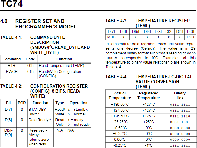
Chapter 4.0 of the TC74 Datasheet (p. 8) discusses the device's RAM organization. From the excerpt below, it can be seen that (read-only) address 0x00 holds the temperature data to be read. Read/Write Register 1 can be programmed to configure the device for certain optimized performance capabilities.
Task.
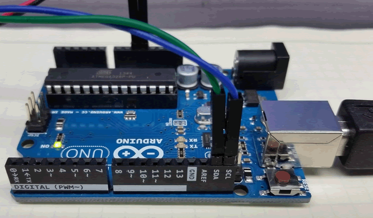
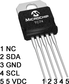 Using the key provided in the image of the TC74 depicted to the right, wire the device to your Arduino.
- Create the Arduino project TC74ReadTemp and replace the template code with this sketch code.
- Examine and upload the code, confirming the (reasonable) accuracy of the data in the Serial Monitor.
- J. Blum offers an inspiring video outlining Processing's visualization of captured TC74 data.
- You'll find a couple of other I2C devices (EEPROM, digital potentiometer, and RTC) discussion in our workbook on pp. 93-94.
SPI: Serial Peripheral Interface
AVR Foundations: pp. 82-83
Reference: Nick Gammon on SPI
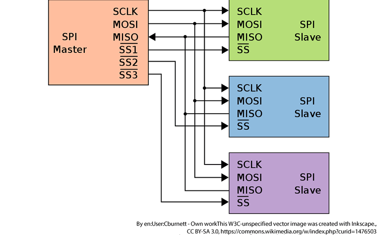 As a reminder, almost any activity performed by native MCU hardware resources is going to be faster than software emulation. So, it is no surpirse that the ATmega328P MCU's built-in hardware SPI device offers extremely fast, full duplex, wired communication between similarly-compatible components (by way of contrast, the ATtiny84 and 85 offer a compliant USI feature that requires partial software support for SPI). As the image to the right depicts, four wires are required to connect the master to a slave (if response from the slave is not required, the MISO wire can be eliminated). Should your MCU master wish to communicate with multiple slave devices, and extra SS line is required for each. The master pulls only one SS line low at a time to exchange data.
At this point in the course, you have, possibly unknowingly, used the SPI concept, twice. The most direct use of the actual SPI hardware was invoked when you used your Pocket AVR programmer to reflash the bootloader to your Arduino using the ISP header (the ISP pins are 1-MISO, 2-5V, 3-SCK, 4-MOSI, 5-RESET, 6-GND). The second (simulated) SPI concept is invoked whenever you use the shiftOut() function. This activity employs clock (SCK), data (MOSI), and latch (SS) pins.
Finally, if you find value in video explanations of Arduino concepts, here's a decent one: Serial Programming Interface and here's its Supporting Tutorial.
| SPI with Morland Bargraph V3 |
SPI with MCP4231 (Dual) Digital Potentiometer |
 |
 |
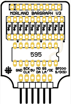
We're going to explore SPI on two different prototypes depicted above. You have a Morland Bargraph V3 for the first investigation and have been given an MCP4231 digital potentiometer for the second.
You've been provided with a hard copy of the code for both projects in the Word document, SPILibraryExamples.docx. The code is also available on our GitHub: https://github.com/rsgcaces/AVRFoundations/tree/master/D_DESIGN_ENGINEERING_PROJECT
Task 1.
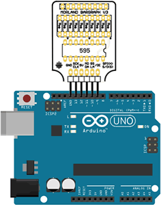
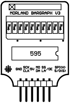 Insert your Morland Bargraph V3 appliance into your Arduino as shown. The SPI-compatible pin arrangement makes this connection the easiest ever.
- Look at the silk screening of the pin labels. These with two labels serve to associate the hardware SPI functionality with the software shiftOut functionality.
- Create the project SPIShiftOut and replace the default code with this sketch code. We'll review the code in class.
- If you upload the code to your prototype you'll see the results of the software shiftOut transfer in that the LEDs 3 and 4 are lit.
- Returning to your code, swap the comment bars in lines 26 and 27. Uploading this version, invokes the hardware SPI transfer yielding the complementary result.
- To conclude, the advantage of the hardware SPI is that it is typically 100× faster using the dedicated three pins than the software alternative. The advantage of the software shiftOut is that it can be undertaken on any trio of pins. Note that this choice parallels our previous investigation of UART: Serial Communications. You can use the hardware UART in pins 0 and 1 only, but SoftwareSerial can be undertaken on any two digital pins.
Task 2.
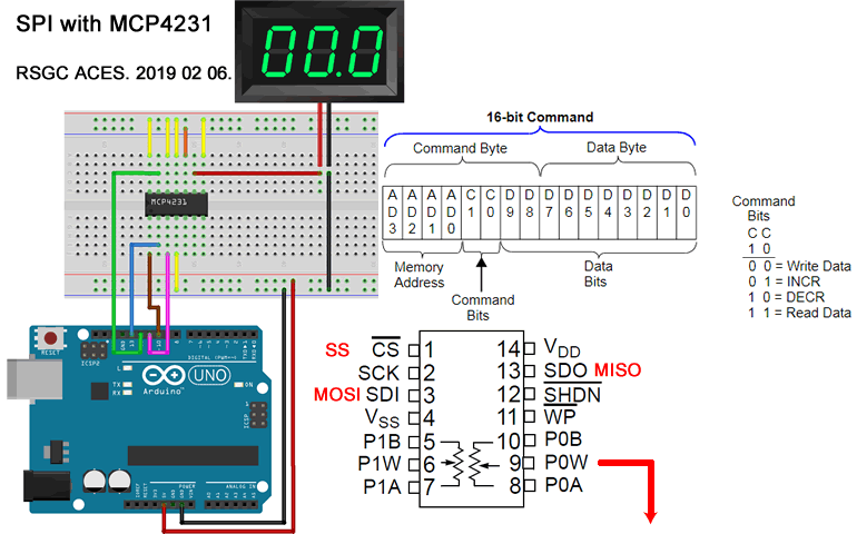
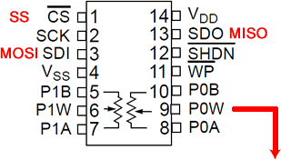 The goal of this investigation is to capture and confirm the varying voltage on Potentiometer 0's Wiper pin (P0W). We won't be using Potentiometer 1.
- Create the hardware prototype depicted in the Fritzing diagram above right, wiring the SPI pins from your Arduino to the MCP4231 as shown. Required pin interpretations are shown in RED. IF you have access to a DMM wire it in as shown. If you do not, wire a resisted LED to P0W.
- Open the MCP4231 datasheet and turn to page 47, Device Commands. Read this intently to get a first-hand appreciation of how this device is to be programmed.
- Create the project MCP4231 and replace the default code with this sketch code. We'll review the code in class.
- If you upload the code to your prototype the DMM Voltmeter should oscillate between roughly 0V and 5V and back to 0V in 128 increments. Open the Serial Monitor to compare the data written (MOSI>SDI) to the device vs the value read (SDO>MISO).
UART: Universal Asynchronous Receiver/Transmitter (Serial Rx/Tx)
References
Datasheet: AVR ATmega328p: USART0
Blog: (Should Read)
U(S)ART: Universal (Synchronous) Asynchronous Receiver/Transmitter
PART 1. AUTONOMOUS ARDUINO
Basic Concept
 Serial Communication involves the 'orchestrated' exchange of single bits, in sequence, between devices.
- Prior to the introduction of the Universal Serial Bus (USB) protocol in 1996, various protocols for exchanging data bits existed, the most common being the Recommended Standard 232 (RS-232).
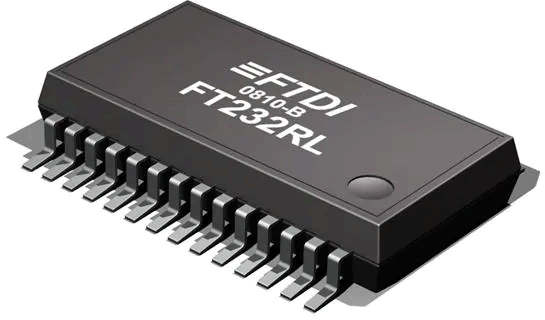
- Dedicated ICs were, and remain, commonly available for RS-232 support. Click on this link to view Digikey's offering of a representative IC. Sparkfun also offers a convenient breakout board featuring this IC as a means of bridging it for USB compatibility.
- Microcontrollers have increasingly incorporated serial reception and transmission capabilities into their design.
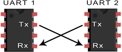
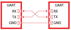
- Two wires are required, one for the transmission of data (Tx) and one for the receiving (Rx). The Tx wire of one party is the Rx wire of the other.
- The coordinated timing can be agreed upon ahead of time (setting a common baud rate-UART) or done with the assistance a separate clock line (USART).
On Your Arduino (ATmega328p)
 The ATmega328P has only 1 hardware UART system onboard. The Arduino Mega2560 has 4.
- The Rx/Tx pins can be found broken out to digital pins 0 and 1 and surface mount LEDs also appear on the Arduino board.
- If you use the standard USB A-USB B cable to program your Arduino you are employing the services of the MCU's Serial UART communication and you can observe the activity on the flashing onboard SMD LEDs.
- If you place an LED or any other device in digital pins 0 and 1 and try to flash new code, the signals are interfered with and your program (and IDE) will very likely hang :(
- On the other hand, AFTER your code is flashed, and your code refrains from employing the services of the Serial Monitor (
Serial.begin(9600));) feel free to place an LED in pins 0 and 1 and develop code to demonstrate blinking.
- It's certainly a hassle disconnecting and reconnecting a component from pins 0 and 1 every time you want to flash new code. So, if you want to use pins 0 and 1 for normal digital use, consider using your Pocket AVR Programmer to flash new code. It does NOT use the UART, but rather the ISP header, a different communication protocol similar to SPI, that we will get to in the classes ahead.
Using the Serial Monitor
- The Serial Monitor (referred to as the terminal window on other systems) is a simple character-based utility that allows you, the user, to interact directly with the ATmega328p's UART, by receiving data bits representing 7-bit ASCII characters, and allowing you to transmit ASCII characters back through the one-line text box at the top.
- The Serial Plotter is a graphic-based utility built ito the Arduino IDE for the purpose of employing the UART to convert received integer data into a 2D Cartesian plot, scrolling right as required.
- The ONE hardware UART device onboard the ATmega328p is available to your code through the resources of the Arduino's core Serial Class.
- Once the UART has been enabled and ready for service, common functions include, available(), read(), write() and print(). Understand their use by reading the class documentation.
- The statement Serial.begin(9600, SERIAL_8N1); you've used many times already is simply a request for the MCU to enable its UART for communication. This action does disable pins 0 and 1 for digital use, so do not invoke the UART if you want those pins for other uses.
- The second parameter shown above is the default value that establishes the rules for the exchange of bits. In this case, we're saying 8 bits are required to form a full 'frame', so no parity-checking will be enforced, and 1 bit is used to mark the end of the frame (stop bit). The other preconfigured constants can be found here.
 Serial Devices
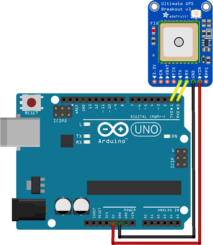
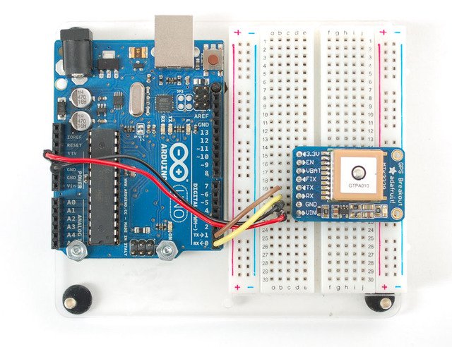
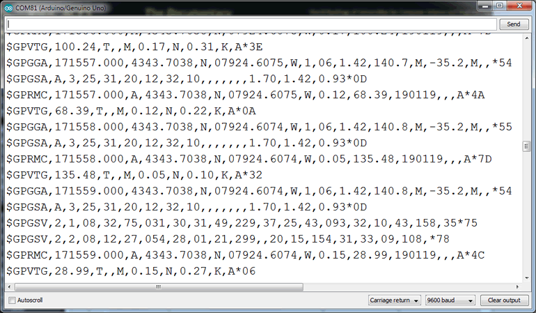
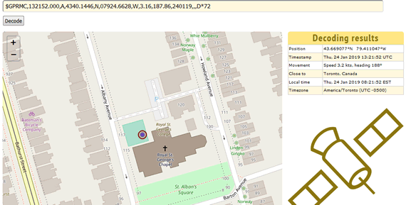
Devices can be acquired that use the serial UART protocol to exchange data with a host (see Sparkfun tutorial). One such device is Adafruit's V3 Ultimate GPS Breakout (antenna sold separately). In this demonstration we'll employ the simple direct wiring example (click on image to the right), bypassing the MCU, using the absolute minimal BlankGPSEcho.ino code. The image below right depicts a stream of National Marine Electronics Association (NMEA) sentences that can be used to interpret position data.
Examples
- [AVR FOUNDATIONS: D. DESIGN ENGINERING PROJECT] SerialEchoTest.ino
- [AVR FOUNDATIONS: D. DESIGN ENGINERING PROJECT] SerialPrintModifiers.ino (activate displayBinary() function for full 8-bit binary presentation)
- [AVR FOUNDATIONS: D. DESIGN ENGINERING PROJECT] DigitalPins0and1.ino (remove the bicolor LED while uploading; insert afterwards)
- [AVR FOUNDATIONS: D. DESIGN ENGINERING PROJECT] Place a square wave on the Serial stream ( Serial1HzSquareWave.ino) and have Processing read the transmission with
File > Examples > Serial > SimpleRead.pde
- [AVR FOUNDATIONS: D. DESIGN ENGINERING PROJECT] TicTacToeAutonomousRandom.ino (this sets us up for Part 2's inter-Arduino game next week) (Word Version)
 PART 2. INTER-ARDUINO SERIAL COMMUNICATION
Part 2 opens the door to a wide-range of projects involving inter-MCU communication. We start with the simplest form of information exchange between two Arduino UNOs using their builtin hardware UART peripherals that you have been exploiting from the beginning. In this introductory confirmation of the 328p's serial communication capabilities you and your partner will set up a CLIENT/SERVER platform.
Task 2A. CLIENT-SERVER COMMUNICATION
- Review the File>Examples>Communication>PhysicalPixel sketch. Upload it to your own Arduino confirm that it responds as expected as you issue the single-character commands H and L from your Serial Monitor. ACES planning to continue into a third year, should consider translating this high-level code to its register-level equivalent. Also, review the commented-out Processing code that appears below the sketch.
- Download the client (transmitter) sketch, SerialClient, and review its contents.
- Grab a partner and identify between the two of you, the roles of CLIENT and SERVER. Do not wire the platform yet.
- The SERVER is asked to upload the PhysicalPixel host sketch to his Arduino.
- Now, wire up the Serial Communication platform as shown below. Note the common ground and that the
Rx pin of one device is connected to the Tx pin of the other.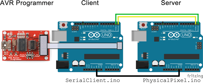
 With its
 Rx/Tx pins engaged, the CLIENT must use his AVR Pocket Programmer as shown to upload the SerialClient code using Sketch>Upload Using Programmer (programming through the ISP header avoids the Rx/Tx interference caused by the USB-Serial cable)- As is, confirm the
 SerialClient code simply flashes the SERVER's pin 13 LED with an 80% duty cycle.
- Let's up the visual interest. Remaining in your pairs, insert a Morland Bargraph in the SERVER Arduino, facing inwards, using the 6 pins: GND, 13,12(5V), 11, 10, and 9. On the SERVER-side, download the sketch
ServerEchoShiftBar and upload it to the SERVER (the CLIENT code can remain as is, transmitting H, L, H, L, ...). If all is well, you should see the binary ASCII values of H and L alternating on the display (other displays you might eventually consider are your Reed Matrix appliance or even a 7-segment display).
- Finally, enhanced CLIENT-side code would enable the client to command the SERVER by entering data through his own Serial Monitor. Alas, this is not possible in this configuration as the hardware UART is tied up communicating with the SERVER Arduino. This temporary limitation is remedied in Task 2B by using software emulation of the UART, through the use of the SoftwareSerial library. A second UART facility also opens the door to two-way, peer-peer communication.
Task 2B. PEER-PEER COMMUNICATION
The ATmega328p's limitation of only one hardware UART peripheral poses a challenge if two ACES want to have a chat through their respective Arduino IDE's Serial Monitor. Fortunately, a software solution to the problem is available in the form of the SoftwareSerial Library that can take over any pair of digital pins for UART emulation of Rx/Tx serial communication. In the configuration below, the hardware serial UART on pins 0 and 1 are used for local Serial Monitor use and pins usescrossed with the partner's software serial UART on pins 11 and 10. A common ground is maintained.
- Review the Arduino's Software Serial Example. Another informative instructable is here.
- Full, two-way serial communication between you and your Arduino UNO partner can be achieved by downloading this similar sketch, Chat.ino.
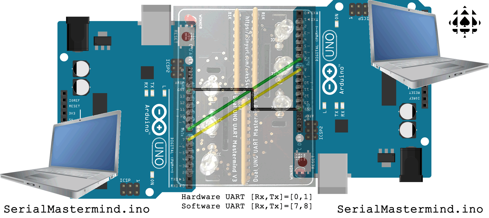
- A review of the code requires a cross-wiring of pins 7 and 8 between each UNO and the comments explain how the hardware and software serial communication lines function. A common ground connection is also required to provide an anchor for the signals.
- After each partner uploads the identical sketch and launches his serial monitor, they (should be) free to have a conversation.
- As of the Spring of 2020, ACES have the
SerialMastermind game available for downloading, testing, and confirmation of peer-peer serial communication between UNO users.
