2025-2026 ICS3U-E Independent Study Projects (ISPs) |
![]() Independent Study Projects. Please read our overview on why ACES pursue Independent Study Projects so vigorously.
Independent Study Projects. Please read our overview on why ACES pursue Independent Study Projects so vigorously.
| Grade | Contribution to Final Mark |
|---|---|
10 |
30% |
11 |
40% |
12 |
60% |
For the bulk of your formal education you have been, and will continue to be, required to consume curriculum chosen for you by someone else. Hopefully you will put this knowledge and skill to good use in your future. However, jumping through someone else's hoops no longer secures future success. For that, you must put yourself in the driver's seat while in secondary school to both cultivate and demonstrate your own unique initiative, motivation, and passion. RSGC ACES program is explicitly built and tailored for you to foster these greater goals. Yes, there is much to learn but there are so many great projects to be undertaken and noble problems to be identified and solved that offer stimulating contexts within which to develop and refine your interests it will quickly seem more than worth the risk, effort, and cost.

 To my mind, the characteristics of a great project include such aspects as imagination, creativity, a degree of risk and, sometimes, even simplicity, to name a few. Check out the flashlight circuit 'board' this guy made out of little more that a piece of paper and a pencil? Simple, but inspiring.
Consider a problem that needs a solution. Boyan Slat did at age 17 when he was in high school; four years later he is
To my mind, the characteristics of a great project include such aspects as imagination, creativity, a degree of risk and, sometimes, even simplicity, to name a few. Check out the flashlight circuit 'board' this guy made out of little more that a piece of paper and a pencil? Simple, but inspiring.
Consider a problem that needs a solution. Boyan Slat did at age 17 when he was in high school; four years later he is ![]() cleaning up the world's oceans. (Update: January 9, 2019) So, dig in, think, dream, research, and explore possible project pursuits. Be discerning: don't accept the first thing that comes along. You'll be expected to maintain the progress of your ISP on your web page to enable everyone to follow your efforts so have your phone handy to at all times to capture the images of your journey. Be conscious of the fact that a multi-page summary of your project will appear in your DER after Presentation Day for more permanent record of your efforts. You may wish to take into account the ISP Evaluation document that will be applied on your Presentation Day.
cleaning up the world's oceans. (Update: January 9, 2019) So, dig in, think, dream, research, and explore possible project pursuits. Be discerning: don't accept the first thing that comes along. You'll be expected to maintain the progress of your ISP on your web page to enable everyone to follow your efforts so have your phone handy to at all times to capture the images of your journey. Be conscious of the fact that a multi-page summary of your project will appear in your DER after Presentation Day for more permanent record of your efforts. You may wish to take into account the ISP Evaluation document that will be applied on your Presentation Day.
Also, don't underestimate the value of an enterprise/entrepreneurial aspect to your project that could see a number of units of your project in the hands of future ACES, for sale in the Dragon's Lair or beyond, reaching an even a broader audience.
The 7Ps of a Successful ISP...Preparation > Proposal > Prototyping > Preview > Production > Presentation > Publication
2025-2026 TEJ3M Independent Study Projects
| ACE | ISP.Long (20%) Wednesday October 15 |
ISP.Medium (20%) Saturday January 31 |
|---|---|---|
| Proposals | ISP.Long Proposal |
ISP.Medum Proposal |
Alex A.
|
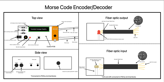
Morse Code Encoder/Decoder (MCED)
DESCRIPTION This project is a Morse code encoder and decoder that sends and receives Morse signals between two identical units, translating received signals into English. The user inputs Morse code using a button, short presses for dots, long holds for dashes. An LCD displays the English translation, while an Arduino Nano handles computation. Communication can be wired (send HIGH/LOW pulses) or optical (fiber optic). For fiber optic, an LED sends light pulses through PMMA fibers, and an LDR or phototransistor receives them. Both communication types have separate input and output lines, are removable, and adjustable in length. The wired connection uses a Shurter DC power jack, and a mode switch lets users toggle between fiber optic and wired communication. A buzzer and LED, controlled by switches, indicate sent and received signals with visual/auditory dots and dashes. Each unit is powered by a DC plug. |
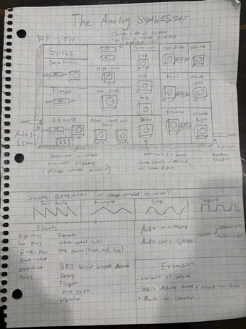
The Analog Synthesizer
MCU None HARDWARE The audio signals are AC with the Analog Synthesizer having a voltage range of -9V to 9V with 0V acting as ground. To amplify, alter and filter effects the audio singles both passive and active components will be used such as RC, LC pairs, voltage dividers, op-amp, 555 timer and BBD (bucket brigade device). Time based effects are made possible by the BBD bucket brigade device using a chain of capacitors to slow down audio signals, effects include (delay, flanger, pitch shift and vibrato). Other effects utilize the properties of resistors, capacitors, diodes, potentiometers and inductors, effects include (high-pass, low-pass, band-pass, band-stop, overdrive, fuzz, tremolo, volume control, tone control). The signal will be shifted to be centered on 0V to account for DC bias and prevent damaging speakers/headphones. SOFTWARE N/A DESIGN The PCB will be designed in EasyEDA (with testing points) and made by JLCPCB, the case will be made in Fusion360 then printed with PLA. MECHANICAL N/A COMMUNCATION |
Tavish B.
|
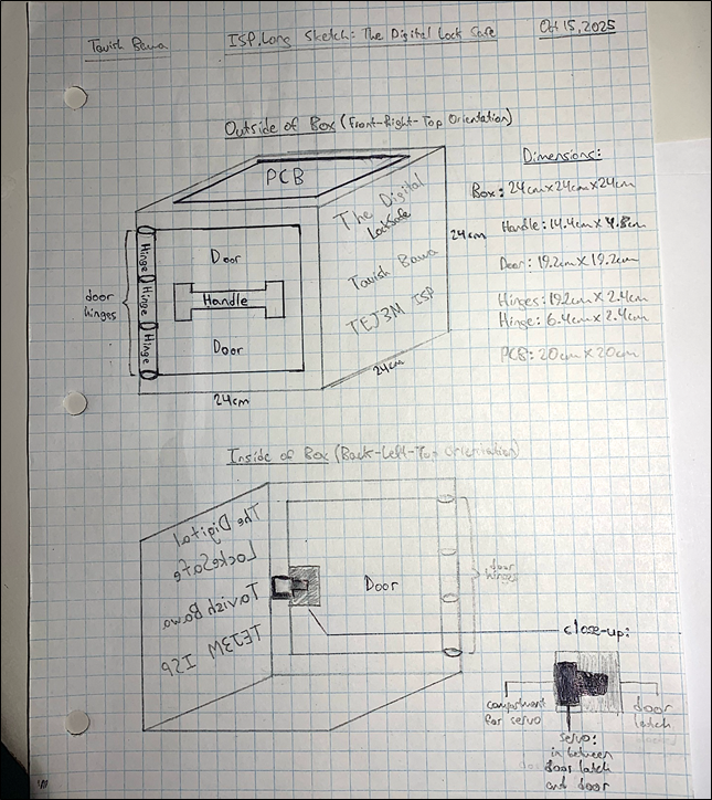
The Digital LockSafe
DESCRIPTION The Digital LockSafe will be a cube-shaped safe with a 12-bit password. The password can be set by the user using a keypad with 14 push buttons. Before setting the code, the user presses a start button, which resets each SR latch. The user then inputs a binary code by pressing (1) or not pressing (0) the 12 PBNO push buttons. This code is stored using NOR gate SR latches. To open the safe, the user toggles DIP switches to enter a 12-bit code and presses the unlock button. XOR and NOT gates act as XNORs to compare each stored bit with the user’s input. If all bits match, the resulting high signals cascade through a ladder of AND gates, producing one final high output. When the unlock button is pressed, the Arduino Nano reads this output. If it is high, a bicolor LED turns green and the servo rotates to unlock the door. If low, the LED turns red and the servo remains locked. The password remains stored in the SR latch, allowing the user to retry. The code can be reset at any time using the latch reset button. |
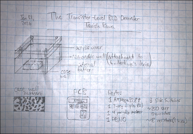
The Transistor-Level BCD Decoder
MCU Optional HARDWARE This project will be built from primarily digital hardware components. The components will work together to drive a seven-segment display from four BCD input signals, emulating the 4511 IC. The device will also feature the display test, blank input, and store features. The project will be prototyped on a breadboard, first unpacked to the logic gate level, and then the transistor-level. SOFTWARE The ATmega328P will provide BCD input signals during standalone operation. It will support two modes: automatic counting and manual input via external switches. A mode-select switch determines which behavior is active. When the microcontroller is held in reset, its input/output pins enter a high-impedance state, allowing Liam N’s binary counter to drive the shared BCD input lines directly. All code will be done at the register-level to improve efficiency. DESIGN The breadboard prototype will be converted into a PCB with identical function. The PCB will be mounted in a 3D-printed encasement, featuring an internal battery and acrylic cover. The case will also have a removable wall, to allow physical attachment to Liam N.’s binary counter device. Wires underneath the PCB in the case will allow for electronic connection. MECHANICAL N/A COMMUNCATION N/A |
Nigel C.
|
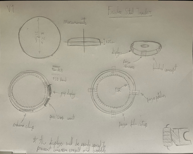
Frisbee Stat Tracker
DESCRIPTION The frisbee stat tracker will count the number of passes and drops that occur during a game as well as airtime. This will allow one to track their statistics for the game. I plan to use a force sensitive resistor to track if it is grabbed for passes and a piezoelectric strip which senses when it is struck to sense the drops. I plan to prototype my design by 3D printing a miniature frisbee and later on modifying a real frisbee. |
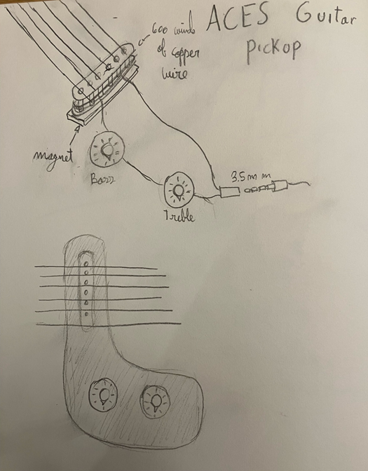
ACES Guitar Pickup
MCU None HARDWARE The single coil pickup will be made out of neodymium magnets and copper wire. The rest of the project will be made up of combinations of capacitors and resistors to make the frequency lower or higher. SOFTWARE None DESIGN I will be using Fusion360 to design a case for the pickup as well as a case to hold the different knobs and dials needed to change the sound. Ideally if I have time I would love to design a guitar but I do not want to lead with that idea. MECHANICAL None COMMUNCATION None |
Nate D.
|
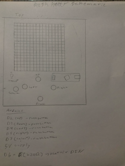
Rush Hour: A Digital Game
DESCRIPTION The board game, called rush-hour converted into a digital game using an LED matrix PCB and case. A multicoloured LED matrix will make the design of the different cars that will be the obstacle, you move the cars around to get your car through, and out. |
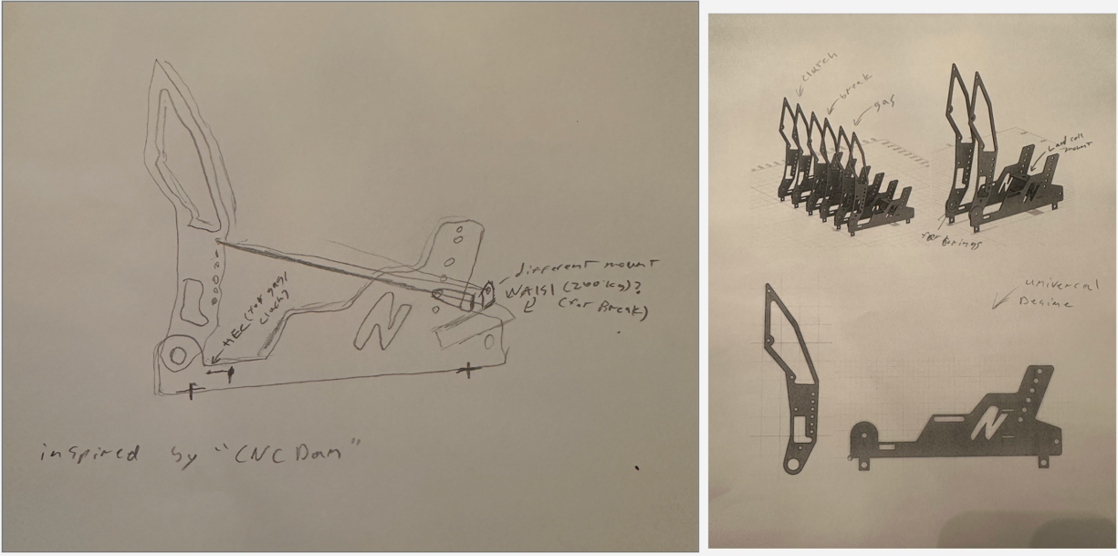
Hall Effect, and Load Cell Simulator Pedals
MCU 328P (Arduino Pro Mini) HARDWARE ? SOFTWARE ? DESIGN Fusion 360 MECHANICAL Different sizes of nuts and bolts, the different metal plates COMMUNCATION USB |
Matt G.
|
4-Digit Digital Passkey
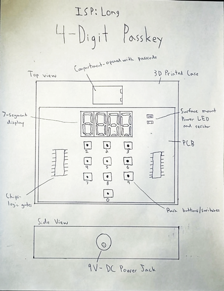
DESCRIPTION The 4-digit digital passkey will be a circuit that will only have a positive output of the correct combination of buttons is pressed. There will be 10 buttons representing integers 0-9. When the correct buttons are pressed, the circuit will output a positive. This positive output will activate a servo motor, lifting a 3D printed hatch and opening a safe. |
Heartbeat Monitor
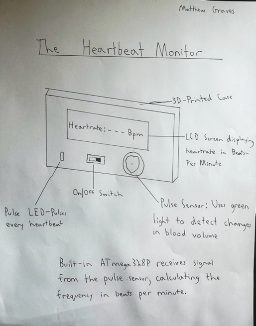
MCU 328p HARDWARE A display will be incorporated onto a breadboard to show the heart rate in beats per minute, while an LED will be used to show each heartbeat. A pulse sensor will be wired to a microcontroller, detecting each heartbeat. A pulse sensor uses green light to detect changes in blood volume. Each change outputs a pulse, which is received by the microcontroller. SOFTWARE An ATmega328P microcontroller will perform all calculations for finding the bpm of the heartbeat. It will receive the signal input from the pulse sensor and determine the intervals between pulses. This interval will be shown on a display driven by the microcontroller. DESIGN A 3D-Printed case will be made with Fusion360 that contains a circuit board from JLCPCB. The circuit board will contain the microcontroller and sensor, as well as any hardware components in the circuit. The circuit board will be contained in the case with a cut-out for the display. MECHANICAL N/A COMMUNCATION SPI communication will be used to program an ATmega328P microcontroller chip inside the device. To drive the display, I2C communication will be used, minimizing the complexity of the circuit. |
Janak J.
|
The ACES Dictaphone
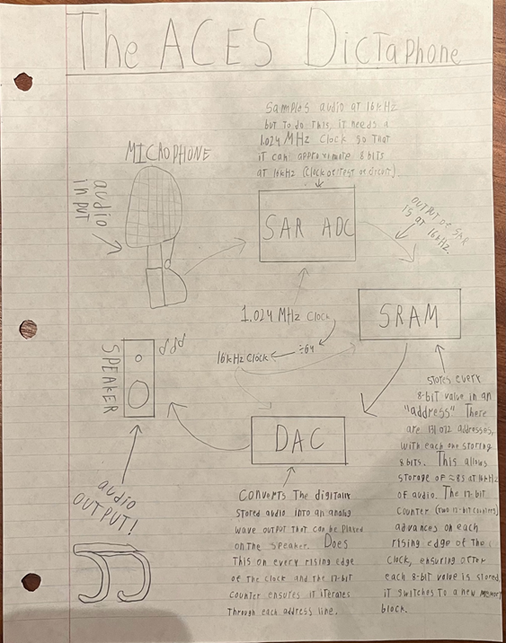
DESCRIPTION The purpose of this project is to be able to record and playback an audio clip (~8 seconds max), using only hardware components. The audio quality will be 16kHz, 8-bit. This project has 5 main parts to it, the input, analog to digital converter, storage, digital to analog converter and the output. The input is an electret microphone, which will be used to record the desired audio. This audio (analog waveform) will get biased to mid-supply (DC offset), amplified and then low pass filtered. The new altered waveform now will be converted using an Analog to Digital Converter (ADC). More specifically, a Successive Approximation Register (SAR) ADC. A SAR ADC is a type of ADC that approximates voltages by essentially playing a “guessing game.” The SAR ADC will be built (not bought) in this project, providing further challenge. This will involve 24 D flip-flops (2 SN74HC273N and 4 SN74HC74N). The SAR ADC clock must be fast enough to perform 8 comparison cycles within each 16 kHz sample period. The ADC will have a clock of 1.024 MHz, which will be generated using part SXOA1.024A20F30TNN. For the rest of the circuit, the same clock will be used, but divided by 64 (to get the 16 kHz we want). This will be done using chip 74HC4040 which is a 12-bit binary ripple counter (use output Q6 for ÷64). This will also ensure that the two different clock signals are in sync with each other. Now that the audio is converted into digital form, it can now be stored into parallel SRAM storage. I will use chip AS6C1008-55PCN which has 1Mbit of storage. Since audio is at 16 kHz for ~8 seconds, this SRAM chip fits (131,072 audio samples). Additionally, a binary counter will generate sequential address signals for the SRAM, synchronized with the system clock. Two 74HC4040 chips will be used for a 17-bit count, which are 12-bit binary counters (same as the clock divider chip), with 12 bits used on the first and 5 on the second. To now play back this stored audio, it is converted back to analog form (since audio is in waveform and was only digitized to store), using an 8-bit R-2R DAC. The DAC converts one 8-bit sample from SRAM every 16 kHz, reconstructing the audio waveform during playback. Next, the output of the DAC gets passed through a low-pass filter to smooth out discrete steps. Then, passed through an amplifier since after the DAC, the signal is still very weak and needs to be amplified before it can drive a speaker. The amplifier’s part # that will be used is LM386N-3/NOPB Finally, a speaker is connected to the amplifier to play the users desired ~8 second audio clip!MCU None? DESIGN I will use EasyEDA to create a PCB and Fusion360 to create a case. COMMUNICATION None MECHANICAL None |
Fast Fourier Transform Spectrum Analyzer
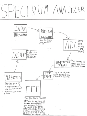
MCU None???? HARDWARE There are a lot of complex hardware aspects of this project. The main focus for this project is the fast Fourier transform (FFT). The FFT will be built, but for other parts (like the ADC), a chip will be used. Additionally, there will be about 4 SRAM chips used to temporarily store the ADC’s output, and 4 ROM chips. The ROM chips store the fixed, sine and cosine values that the FFT relies on. These values never change. SOFTWARE N/A DESIGN Fusion360 will be used to create a case for the final PCB. MECHANICAL N/A COMMUNCATION None |
|
|
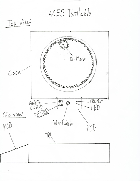
The ACES Turntable
DESCRIPTION The device will be a circular disk attached to a DC motor through pinion and spur gears. It will rotate in forward or reverse at various speeds. It will be used to show off finished projects or objects. This project will really challenge my design skills as well as my time management skills. The main challenge with the design will be making the table spin smoothly. |
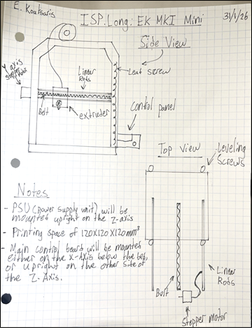
EK Mk. I Mini
MCU STM32F103 (32-bit ARM, Creality V4.2.2 Ender 3 Pro Control Board HARDWARE The printer will be controlled using a Creality Ender 3 Pro V4.2.2 control board, which is based on a 32-bit STM32 microcontroller. The printer will use NEMA 17 stepper motors for the X, Y, Z, and extruder axis, with onboard stepper motor drivers on the control board. Motion will be guided using smooth linear rods with linear bearings, and belt and pulley systems will be used for the X and Y axes. The Z axis will use dual lead screws for increased stability. The printer will include mechanical endstop switches on each axis, a direct-drive extruder, and a standard hot end with a thermistor for temperature sensing. Cooling will be provided by dedicated hot end and part cooling fans. User interaction will be handled through an LCD screen with a rotary encoder. Power will be supplied using a 24V power supply unit. SOFTWARE The printer will run using Marlin firmware configured specifically for the Creality Ender 3 Pro V4.2.2 control board. The software will be heavily modified to account for the smaller bed size and overall dimensions. The firmware will interpret standard G-code files generated by slicing software and convert them into precise motor movements. Marlin will handle stepper motor control, acceleration, and motion planning, as well as temperature monitoring using thermistors. The firmware will also manage the LCD menu system and rotary encoder input, allowing the user to control the printer directly from the screen. Communication between the printer and a computer will occur via a micro SD card. DESIGN The printer will be designed using Fusion 360 to model the frame and custom mechanical components. This includes motor mounts, extruder mounting hardware, and custom fan ducts for hot end cooling. Some design elements will be inspired by existing open-source 3D printer designs and adapted to fit the size and layout of the printer. All components will be designed to be manufacturable using standard 3D printing methods. MECHANICAL All motion in the printer will be driven using stepper motors. The X and Y axes will use belt-driven motion systems, while the Z axis will use dual lead screws to raise and lower the gantry. The extruder will be directly mounted to the hot end for improved filament control and extrusion accuracy. A rotary encoder will be used as the primary user input device, and multiple fans will be used to cool the hot end, printed part, and electronics. COMMUNCATION The printer will operate using microSD card communication. G-code files will be loaded onto a microSD card and read directly by the control board during printing. This allows the printer to operate independently from a computer once a print has been started. Internal communication between components such as the LCD and control board will use standard digital communication methods. |
Zack L.
|
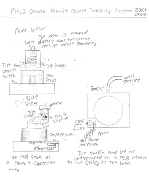
Pixy2 Camera Pan-Tilt Object Tracking System
DESCRIPTION The pan-tilt bracket will be designed in Fusion 360. It will be designed to be small to allow for minimal printing time, allowing more iterations to be created. In addition, the bracket will be designed to account for the camera and laser’s weight and to have the center of balance aligned on the tilt servo’s axis. This will allow for jitter-free motion. A small custom PCB will also be designed in EasyEDA. This PCB will serve as a power and connection hub. |
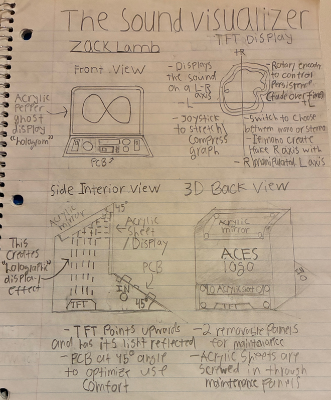
The Sound Visualizer
MCU 328p HARDWARE The sound is inputted through a 3.5 mm TS or TRS jack. Since audio hovers around 0 V, which is unreadable by the ATmega328P, a voltage divider in combination with several 100 kΩ fixed resistors and small capacitors will be connected in parallel with the audio signals going to the Nano’s analog pins. This forces the audio signal to hover around 2.5 V. For stereo (TRS), the left and right audio signals will be plotted on a graph with each signal being an axis. This will allow for various interesting patterns controlled through audio to appear such as Lissajous curves. There will be a slide switch to switch between stereo (TRS) and mono (TS). The slide switch’s output terminals will be connected to VCC and GND and the common terminal will be connected to one of the Nano’s digital pins. To use mono in this project it is done through software. The sound can be outputted and listened to through the Nano’s PWM pins, but it does have to filtered and lowered to hover around 0 V once again before it can be plugged into anything. To do this it is essentially the same system that was used in the input, except done in reverse. SOFTWARE The circuit is built off of an ATmega328P. For stereo, the MCU reads the L and R signal from its analog pins, and plots it on a graph with the L signal being the x-axis and the R signal being the y-axis. Since the incoming audio is hovering around 2.5 V, the Nano will use 512 as the origin for both axes. The MCU will then plot the incoming sound on the graph and Lissajous and other patterns will form depending on the specifics of how it is plotted. There will be mechanical devices which can manipulate the graph by changing the L and R values. To create the persistence effect, the screen will be cleared less often. For mono, there is only a L signal and no R signal, therefore the L signal needs to be replicated and slightly delayed. This new signal will act as a fake R allowing for more interesting patterns to be created. There will also be a simple display done through EEPROM that will appear on the display when it is first turned on displaying Z. LAMB and the ACES logo. DESIGN The TFT will be shining directly upwards inside a case. Above the TFT there will be an acrylic mirror at a 45º angle which will reflect the TFT’s light onto an acrylic sheet which will display the visualized sound. The case will have the PCB on a 45º angle below the acrylic so that it is at an optimal angle for use. This case will be 3D printed with black plastic and will form a box around the acrylic so that the holographic display has the maximum contrast possible, which is what is wanted with a pepper ghost display. The TFT will be hidden from view to emphasize the effect. The back of the case will have two panels that will be able to be unscrewed for assembly and maintenance. All sharp edges will be filleted for aesthetic. MECHANICAL There will be a joystick to transform the displayed sound through stretching or compressing it. There will also be a slide switch that can set a certain joystick position and lock it until the switch is turned off. A rotary encoder will also be included to change the persistence. What this means is the amount that the previous trail that the sound took is visible. The greater the persistence, the more of where the sound has already been is visible. If the rotary encoder’s switch is pressed it will reset the persistence to 0. Finally, there will be a potentiometer to increase or decrease the frequency/speed of the display. COMMUNCATION The ATmega328P will be programmed using SPI. The 2.4” TFT will also be using SPI communication. This means that both the programmer and the TFT will be wired in parallel with the ATmega328P’s SPI pins. |
Zach M.
|
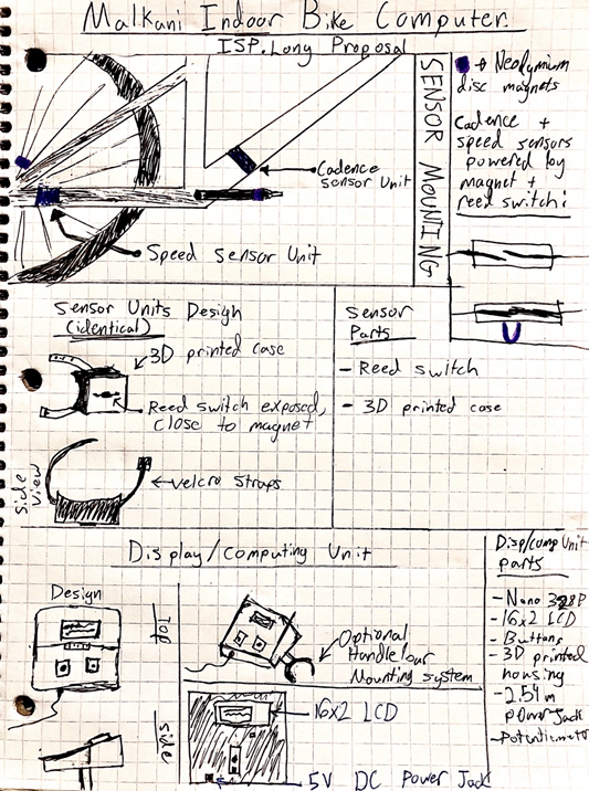
Malkani Indoor Bike Computer
DESCRIPTION A bike computer system that tracks wheel and pedal RPM and displays a live reading of the Cadence and Speed the user is pushing. There will also be a single Start/Reset button to begin the stopwatch and a corresponding distance meter. Further versions could also connect any HRM (Heart rate monitor) to further enrich the users training. |
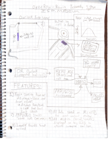
openRow - Open-Source Rowing Telemetry System
MCU ESP32, because the Force inputs accuracy benefits from the higher clock speed (in comparison to 328P) HARDWARE The force sensor will be integrated into an oarlock, which will be 3D printed in CF-PETG material, for high structural integrity under up to 300 lbs of force from the rower at the peak of the stroke. The force sensor will communicate with the MCU via a HX711 ADC as a load cell amplifier. The SPM will be tracked with a MPU6050 accelerometer due to its low cost and accuracy. Boat speed will be tracked with a 3D printed impeller and reed switch for a consistent accurate output, and all data will be stored using a MicroSD module. Finally, the system will be powered via a Lithium Polymer cell that is able to be charged while in the case. SOFTWARE All code will be in ArduinoIDE on the ESP32. The goal of the software in this project is to be function and provide accurate results. Afterwards, the goal is to make it as lightweight, efficient and streamlined as possible. DESIGN All parts including the Oarlock, Computing/Display Module case, and impeller will be 3D printed with CF-PETG and regular PETG for stronger and more durable parts. A PCB will be made for the computer module via EasyEDA and JLCPCB. As this electronic project will be exposed to a lot of water, the computing/display module case will be splash resistant. Splash resistance of electronics will be the main focus of the design. MECHANICAL None COMMUNCATION All inputs/outputs of the MCU will communicate through I2C. |
Grayson M.
|
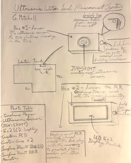
Ultrasonic Water Level Measurement System (UWLMS)
DESCRIPTION This systems purpose is to measure the fill capacity of a water cistern (5000L specifically). It will assess the water level in the tank by measuring the distance to the surface from a ultrasonic sensor, relative to precalculated dimensions in the tank. This distance will then be converted to the percentage of tank filled, then outputted to a display. |
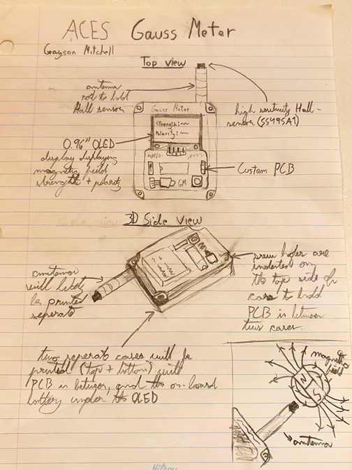
ACES Gauss Meter
MCU 328p HARDWARE The project will use the ATmega328P microcontroller for processing and display control. The linear Hall sensor (SS495A), is used to measure the magnetic field strength. A 0.96” OLED display is controlled by the ATmega. The circuit will use a voltage regulator to create a steady 5V. SOFTWARE Arduino IDE will be used to control the actions of the Hall sensor and OLED display. The microcontroller will sample the reading from the Hall sensor very frequently, likely using an averaging system. These reading will then be outputted to the OLED on the top of the case. DESIGN EasyEDA will be used to make a PCB with all of the electronic parts. Fusion360 will be used to create a case to mostly enclose the PCB, along with make an antenna for the Hall sensor. The case will leave an area open on the top to show the on/off switch and a PBNO. MECHANICAL None COMMUNCATION I2C is used for the communication between the microcontroller and the OLED display. |
Liam N.
|
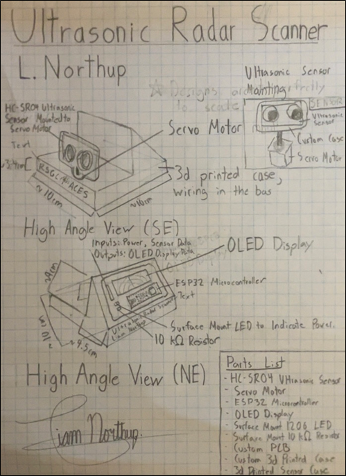
Ultrasonic Radar Scanner
DESCRIPTION This project is an ultrasonic radar scanner capable of measuring distances and mapping the surrounding environment. A ESP32 microcontroller controls a servo motor to rotate an ultrasonic sensor (HC-SR04) across a 180˚ plane. The sensor emits ultrasonic pulses and measures the time taken for echoes to return, allowing distance calculation. Readings from multiple angles are processed by the microcontroller and visualized on a display (OLED) to create a map of nearby objects. |
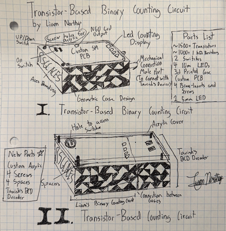
Transistor-Based Binary Counting Circuit
MCU None HARDWARE The hardware for this project will consist of a custom surface-mount PCB that demonstrates digital counting circuitry fully unpacked to the transistor level. A NAND gate oscillator built from individual transistors, resistors, and capacitors will generate a clock pulse using RC timing. This clock signal will drive a transistor-level 4510 binary counter. The output of the counter will be displayed using LEDs to visually represent the binary count. The device will be powered by an internal battery, connected to the PCB using a terminal block. SOFTWARE None DESIGN The design of my device involves the PCB design, Case Design, and Acrylic. The PCB will be laid out in clearly separated blocks containing transistors to show the different components that have been unpacked. Test points will also be present on the PCB for troubleshooting prototypes. The enclosure will be a custom 3D-printed case designed around the PCB and features modern geometric design for visual appeal. A mechanical docking interface aligns and locks with Tavish B.’s Transistor-Based BCD Decoder. MECHANICAL None COMMUNCATION None |
Neal S.
|
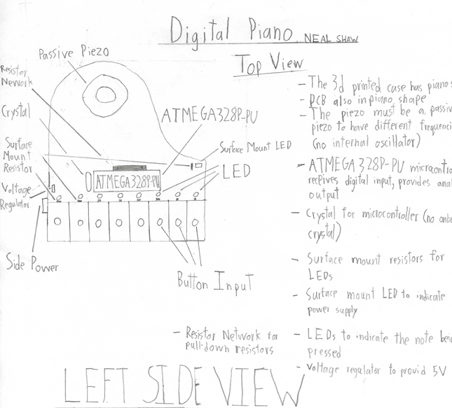
Digital Piano
DESCRIPTION The Digital Piano will have 8 inputs that will serve as piano keys. Every input corresponds with a digital read pin on a ATMEGA328P-PU. If a pin reads high, an analog output will go out of a different pin. Depending on with button is pressed, the Pulse Width Modulation (PWM) will change in the analog output. This output will be connected to a piezo, which will produce different frequencies as different voltages are given to it. |
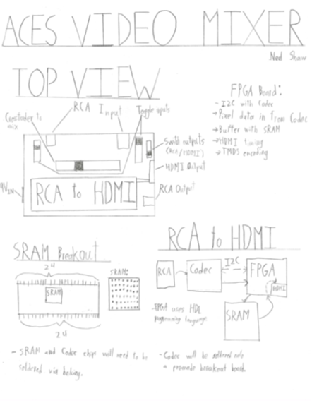
ACES Video Mixer
MCU GoWin FPGA HARDWARE The hardware to mix videos is quite simple. The conversion to HDMI is the source of hardware for this project. The RCA signal will go through a video decoder, controlled through I2C. The FPGA board will then take the video data, and frame buffer the individual frames using SRAM. The FPGA will also create HDMI timing before TMDS encoding the video. The board has a built-on HDMI port. SOFTWARE The FPGA board uses GowinIDE. The programming language for this IDE is HDL. This board uses I2C communication to collect video data from the decoder. This board will have to load information into SRAM, as well as retrieving information. There will need to be code to handle HDMI timing. The TMDS encoding will also need to be written. DESIGNJLCPCB will be used to create a breakout board for the SRAM chip, as well as the final device PCB. Fusion360 will be used to create a 3d printed case. MECHANICAL None COMMUNCATION I2C |
Finn S.
|
Electronic Dice
DESCRIPTION Two sets of 6 sided die that random choose a number from one to six then added together to give a score for any dice related game |
Infrared Tripwire
When the IR beam is broken, the Arduino detects the change using an interrupt service routine (ISR). The microcontroller then activates a GSM module, which sends a text message alert to a predefined phone number. The system is designed to remain in a low-power state until the tripwire is triggered. MCU 328p HARDWARE The hardware includes an Arduino Nano (ATmega328P) as the main controller, an infrared LED transmitter circuit, and an infrared receiver circuit. A GSM module (such as SIM800/900 series) is used to send SMS messages when the tripwire is broken. Power is supplied using a rechargeable 18650 lithium-ion battery with a voltage regulator to provide stable operating voltage. Supporting components include resistors, capacitors, transistors or SOFTWARE The software will be written using the Arduino IDE.The program will use hardware interrupts (ISR) to detect changes in the IR receiver signal. Low-power sleep modes will be implemented so the system remains idle until the tripwire is broken. Serial or SPI communication will be used to interface with the GSM module, and existing GSM libraries will handle SMS transmission. DESIGN Fusion 360 will be used to design the mechanical enclosure and mounting hardware. EasyEDA will be used to design schematics and PCB layouts for both the transmitter and receiver circuits. PCBs may be manufactured using JLCPCB. MECHANICAL N/A COMMUNCATION SPI, IR, Serial and GSM |
Sam V.
|
A Ground Based Weather Station
DESCRIPTION This project will involve creating a miniature weather station that can deliver real-time data to a device like a phone or computer. The station will use a variety of components, including humidity, pressure, and temperature sensors to collect data. Additionally, an anemometer and a wind vane will be included to measure real-time wind speed and direction. The project is planned in two parts. The first part will be a simple, ground-based weather station. The second part will be either an area ???? |
Radio Telescope
MCU Laptop MCU(x86_64), 328p for Stepper Motors HARDWARE In order to collect and reflect radio waves from space into the receiver, I will use a standard parabolic satellite dish, preferably around 1m in diameter. To serve as a waveguide, I will use a tuned coffee can (or similar metallic cylinder) to direct the reflected waves into the probe. For the receiver, I will utilize the RTL-SDR Blog V4, which samples the analog radio signature and converts it via an Analog-to-Digital Converter for the computer to process through a USB interface. To boost the faint signals from the galaxy, I will integrate a Low Noise Amplifier (LNA) specifically filtered for the hydrogen-line frequency. Finally, for any custom mounting or housing, I will use PETG plastic for its superior weatherproofing and UV resistance SOFTWARE For my primary coding language, I'll use C++. The chip I will be using is my computer MCU as any other chip would be too slow to properly receive these radio signatures. In order to actually visualize these radio signatures going through space I'll be using a visualizer in Python called Matplotlib As it is easy to set up and the information comes from the C++ code into a CVC text file within its red by the python and converted in a visualization DESIGN For a robust design, I will use Fusion 360 to model and create a specialized housing and mounting hub for my radio telescope components. This will ensure mechanical stability and precise alignment of the feedhorn at the dish’s focal point. Additionally, I may use EasyEDA to design a custom PCB for auxiliary power management or sensor integration; however, this remains an optional expansion depending on the primary system's stability. MECHANICAL For motion control system I will implement 12 volt stepper Motors. These motors will be controlled by either a Heltec V3, Or in Arduino Nano using dedicated stepper drivers to provide motor stepping for Celestial tracking COMMUNCATION For communication of primarily be using radio frequency which will detect the strands of hydrogen within space. And to communicate that information to my laptop it will be through a serial data code or usb-c 2.0. This will allow for extraordinarily fast transmission of data and large samples of data. |