2024-2025 ICS3U-E Independent Study Projects (ISPs) |
![]() Independent Study Projects. Please read our overview on why ACES pursue Independent Study Projects so vigorously.
Independent Study Projects. Please read our overview on why ACES pursue Independent Study Projects so vigorously.
| Grade | Contribution to Final Mark |
|---|---|
10 |
30% |
11 |
40% |
12 |
60% |
For the bulk of your formal education you have been, and will continue to be, required to consume curriculum chosen for you by someone else. Hopefully you will put this knowledge and skill to good use in your future. However, jumping through someone else's hoops no longer secures future success. For that, you must put yourself in the driver's seat while in secondary school to both cultivate and demonstrate your own unique initiative, motivation, and passion. RSGC ACES program is explicitly built and tailored for you to foster these greater goals. Yes, there is much to learn but there are so many great projects to be undertaken and noble problems to be identified and solved that offer stimulating contexts within which to develop and refine your interests it will quickly seem more than worth the risk, effort, and cost.
 To my mind, the characteristics of a great project include such aspects as imagination, creativity, a degree of risk and, sometimes, even simplicity, to name a few. Check out the flashlight circuit 'board' this guy made out of little more that a piece of paper and a pencil? Simple, but inspiring.
Consider a problem that needs a solution. Boyan Slat did at age 17 when he was in high school; four years later he is
To my mind, the characteristics of a great project include such aspects as imagination, creativity, a degree of risk and, sometimes, even simplicity, to name a few. Check out the flashlight circuit 'board' this guy made out of little more that a piece of paper and a pencil? Simple, but inspiring.
Consider a problem that needs a solution. Boyan Slat did at age 17 when he was in high school; four years later he is ![]() cleaning up the world's oceans. (Update: January 9, 2019) So, dig in, think, dream, research, and explore possible project pursuits. Be discerning: don't accept the first thing that comes along. You'll be expected to maintain the progress of your ISP on your web page to enable everyone to follow your efforts so have your phone handy to at all times to capture the images of your journey. Be conscious of the fact that a multi-page summary of your project will appear in your DER after Presentation Day for more permanent record of your efforts. You may wish to take into account the ISP Evaluation document that will be applied on your Presentation Day.
cleaning up the world's oceans. (Update: January 9, 2019) So, dig in, think, dream, research, and explore possible project pursuits. Be discerning: don't accept the first thing that comes along. You'll be expected to maintain the progress of your ISP on your web page to enable everyone to follow your efforts so have your phone handy to at all times to capture the images of your journey. Be conscious of the fact that a multi-page summary of your project will appear in your DER after Presentation Day for more permanent record of your efforts. You may wish to take into account the ISP Evaluation document that will be applied on your Presentation Day.
Also, don't underestimate the value of an enterprise/entrepreneurial aspect to your project that could see a number of units of your project in the hands of future ACES, for sale in the Dragon's Lair or beyond, reaching an even a broader audience.
The 7 Ps of a Successful ISP...Preparation > Proposal > Prototyping > Preview > Production > Presentation > Publication
2024-2025 Independent Study Projects
| ACE | ISP.Long (20%) Tuesday October 15 |
ISP.Medium (20%) Saturday February 1 |
|---|---|---|
| Proposals | ISP.Long Proposal |
ISP.Medum Proposal |
| Evaluations | ||
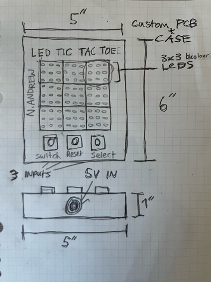
Nathan A.
|
LED Tic Tac Toe
MCU 328p DESIGN The PCB will be designed using EasyEDA, and the case will be designed in Fusion and created using a 3D printer. COMMUNICATION The communication will rely on serial for button inputs and LED control. MECHANICAL N/A |
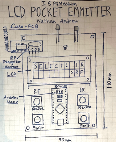
LCD Pocket Emitter
MCU 328p HARDWARE Controller: Arduino Nano IR Section: TSOP38238 IR Receiver, TSAL6200 IR LED RF Section: FS1000A RF Transmitter, MX-RM-5V RF Receiver, 20 cm antenna wire User Interface: 16×2 LCD, Tactile push buttons SOFTWARE Arduino IDE Libraries: IRremote, RadioHead, LiquidCrystal Functions: Copy Mode and Emit Mode Techniques: Interrupts, Debounce, Bitwise DESIGN JLCPCB & Fusion MECHANICAL N/A COMMUNCATION IT & RF |
Austin C.
|
Wireless Charging Stand
MCU None DESIGN EasyEDA to create a PCB and Fusion 360 to design a stand. COMMUNICATION None MECHANICAL None |
Remote Controlled and Automatic Cat Laser
MCU 328p HARDWARE Joystick, Laser and servo motor SOFTWARE Code for the joystick, code for the servo motors and code for the automatic mode. DESIGN PCB & Fusion case MECHANICAL Servos for X & Y positioning COMMUNCATION N/A |
Julian D-S. |
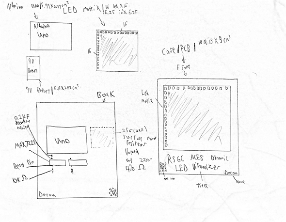
Dynamic 2D Display on an LED Matrix
MCU 328p DESIGN Case: Material: 3D-printed plastic. Mounting: Standoffs for the Arduino and snug slots for the matrix. Ventilation: Small cutouts for airflow if needed. PCB: Matrix Control: I will use a driver like MAX7219 or WS2812B addressable LEDs to simplify wiring. Power: External 5V or 12V power supply, with proper current-limiting resistors. Connectors: Include detachable connectors for ease of assembly. Misc: Capacitors: Decoupling capacitors for voltage stability. COMMUNICATION I will use SPI as it is faster then I2C, it is optimized for dynamic changes that I will include in this matrix MECHANICAL N/A |
GlowLog, Git Display
MCU ESP12E WiFi HARDWARE • LEDs: 30x LEDs (single data pin, chainable). • Power: 5V • Misc: 330Ω resistor on data line, 1000µF capacitor across LED power. SOFTWARE • GitHub API: Pulls commit history via /users/{username}/events (filters PushEvent). • Auth: Personal access token (PAT) stored locally. • Brightness tiers: 0=off, 1-3=20%, 4-6=60%, 7+=100% (mapped to GitHub’s 4-color logic). • Cron job: Auto-refresh daily at midnight (no manual updates). • Libraries: FastLED (LED control), ArduinoJSON (API response parsing). DESIGN• Case: Simple black case designed for PCB • PCB: Black PCB with 3x10 LEDs well organized • Labeling: Tiny etched day numbers (1-30) below LEDs. MECHANICAL N/A COMMUNCATION • WiFi: ESP-12E fetches data directly from GitHub API (no external computer). • LED protocol: Single-wire serial (FastLED library) on GPIO pin D4. |
Hunter G.
|
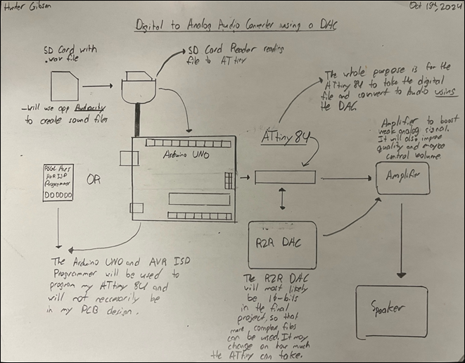
Digital-to-Analog Audio Converter
Step 1: The ATtiny84 reads digital audio data from the SD Card Module. MCU mega328p & tiny84 DESIGN The circuit design will be done in EasyEDA for the DAC and ATtiny84 boards. Fusion360 will be used to design a 3D-printed Case for the whole project. COMMUNICATION SPI will be used to transfer the digital audio data from an external source (e.g., a computer or SD card) to the ATtiny84 and the DAC. MECHANICAL I will be using a speaker as the output of my Converter as well as a SD Card reader that will be able to transfer file on SD card to my ATtiny84. |
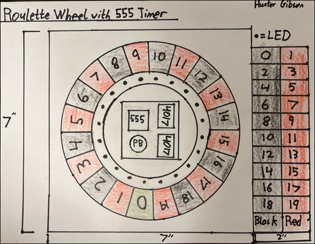
The Roulette Wheel
MCU None HARDWARE • 555 Timer: Configured in astable mode to generate a clock pulse. • 4017 Decade Counter IC: Two ICs used to drive 20 LEDs. Each IC counts from 0 to 9, and together, they enable the control of 20 individual LEDs. • 20 LEDs: Sequentially lit to simulate the spinning of the roulette wheel. • Resistors and Capacitors: For controlling the timing and operation of the 555 timer and 4017 ICs. SOFTWARE None DESIGN For the design of the 20 LED Roulette Wheel project, I will create a custom 3D case using Fusion 360. The case will securely hold all components, including precise cutouts for the 20 LEDs, and compartments for the 555 timer and two 4017 ICs, with easy access to power connections and external components. A custom PCB will be designed through JLCPCB, integrating the 555 timer and 4017 ICs while providing a compact, organized layout with minimal wiring. The PCB will be optimized for easy assembly, with clear component markings. I aim to create an aesthetically pleasing and finished look, as it is the main focus of this project. I feel my design skills are not up to par in this course and this project is an opportunity to improve my skills. MECHANICAL None COMMUNCATION None |
Elliot H.
|
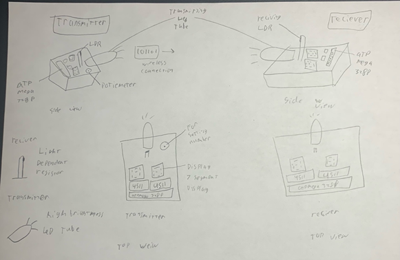
Photon Wireless Communication Network
MCU 328p DESIGN Using easy EDA to create 2 PCBs for either computer, and using fusion360 to create a case that can hold a power supply for both computers. COMMUNICATION Using visible photons to wirelessly communicate (might have to complete demonstrations in a dark room) MECHANICAL N/A |
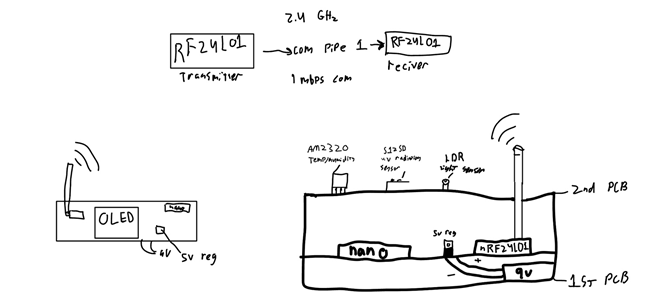
AtmosLink
MCU 328p HARDWARE nRF24L01 – Radio Transceiver Arduino Nano – microcontroller AM2320 – Temperature/ Humidity sensor S12SD - UV sensor LDR – visitable light detector. 5v regulator SOFTWARE The transmitting node takes all the information from the sensors, packages it and sends it to the receiver to display on the OLED screen. DESIGN Fusion 360 for custom 3D printed case And JLCPCB for 3 custom PCBs. MECHANICAL N/A COMMUNCATION Using I2C for some of the Sensors, SPI for communication to the RF module, and RF between modules. |
Naol K.
|
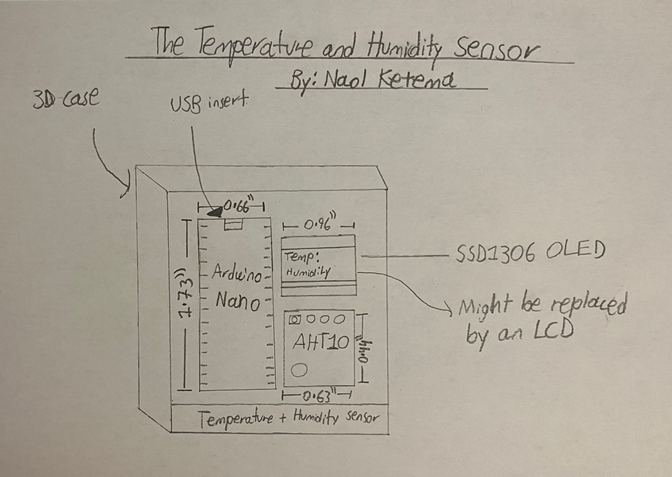
The Temperature and Humidity Sensor
MCU 328p (Nano) DESIGN EasyEDA, Fusion 360 COMMUNICATION AHT10 Sensor Module communicates through the I2C interface with the MCU. MECHANICAL N/A |
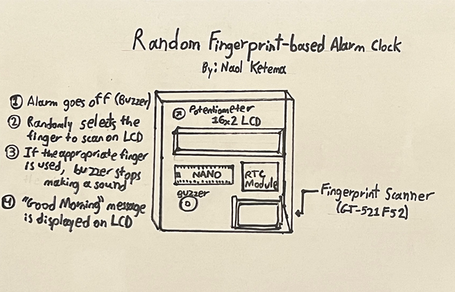
Random Fingerprint-based Alarm Clock
MCU 328p HARDWARE - Liquid Crystal Display (16 rows by 2 rows) - Arduino Nano - DS3231 RTC Module - Buzzer/Speaker - Fingerprint Scanner GT-521F52 or similar Fingerprint Sensor Module - Potentiometer (for the LCD) SOFTWARE - for the time (RTC) - fingerprint sensor GT-521F52 - displaying messages on the Liquid Crystal Display - Buzzer DESIGN - Perma-protoboard - Fusion360 - EasyEDA (Undecided) - JLCPCB (Undecided) MECHANICAL N/A COMMUNCATION - Serial , - I2C, - Digital Input/Output |
Thomas La.
|
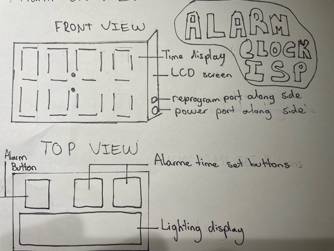
Alarm Clock
MCU ESP8266 DESIGN Easy eda will be used to create a custom PCB for the final project. This PCB will match a fusion 360 design so that it takes the appearance of an actual alarm clock. COMMUNICATION The I2C will be used to properly connect the LCD used to display the time and alarm. An RTC (real time clock) module will also be used to update the circuit with the proper time. Finally serial communication will be used to update the code and transmit it to the nano. MECHANICAL N/A |
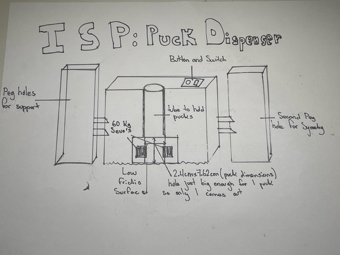
Hockey Puck Dispenser
MCU 328p HARDWARE An Arduino UNO (?) will be used to power the motors, and a button and switch will be connected to the UNO to turn on the system and launch the pucks. SOFTWARE Arduino will be used to control the motors so that they move at the highest available speed to send the puck as fast as possible. No libraries will be used. DESIGN Fusion will be used to create a fully custom casing for everything to be protected. JLC will be used to create a custom PCB to connect everything together MECHANICAL 2 60Kg/cm servo motors will be used to launch the mini pucks out. COMMUNCATION Serial |
Nathan LN. |
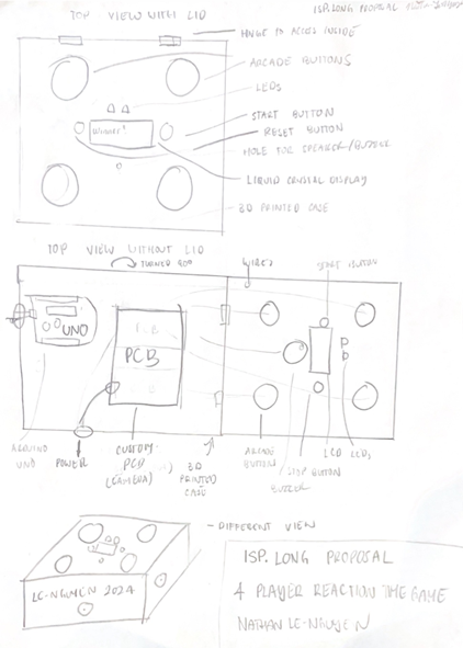
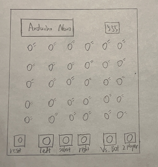
The 4 Player Reaction Time Game
MCU 328p (UNO) DESIGN EasyEDA, Fusion360 COMMUNICATION Serial communication for displaying results and troubleshooting I2C for LCD display communication MECHANICAL N/A |
The SafeKit
MCU 328p HARDWARE • Arduino Uno (ATmega328P) as microcontroller for extra pins, processing user input and controls locking mechanism • 4×4 Keypad to input the password for authentication, sends inputs to Arduino, uses matrix wiring • I2C LCD to display feedback on password entry, status, other prompts, uses I2C communication to reduce wires SOFTWARE • Libraries Used: LiquidCrystal_I2C (for LCD display), Keypad (may not be used), Servo (for motor control) • Password Handling: Stored in EEPROM (non-volatile memory), can only be set once for security • Authentication System: User enters a password via keypad, If correct, the servo unlocks the door, If incorrect, the system denies access and stays locked DESIGN Fusion360 for Case, Door, Locking Mechanism Design JLCPCB for Custom PCB MECHANICAL Servo Motor (25 kg/cm torque or other high-torque servo motor) COMMUNCATION I2C for LCD |
Thomas Lo.
|
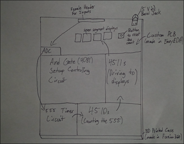
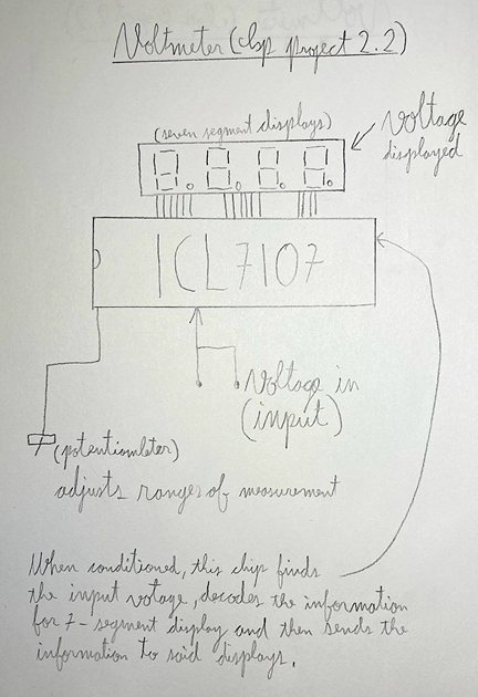
5V Voltmeter
DESCRIPTION This circuit will be able to measure any voltage between the ranges of 0 to 5 volts. It will achieve this through the use of an analog-to-digital converter, and logic chips like the 4510 and 4511. The voltage that is read will be displayed on four seven-segment displays so that the result is accurate to the millivolt and there will be a button to reset the display. Additionally, the final prototype will include a custom 3D printed case along with a custom-made PCB. |
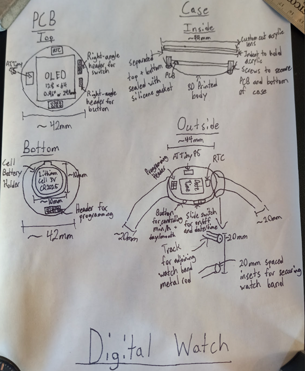
Digital Watch
MCU ATtiny85 HARDWARE The watch features a button and slide switch that can change the date and time as well as turning the watch off and on. As well the power of the circuit is derived from a 3V lithium cell battery. This power will be drawn from a battery holder attached to the PCB. SOFTWARE The watch features an ATtiny85, an RTC, and an OLED display, all of which must be programmed to work in unison. Additionally, the PCB utilizes a six-pin header to program the ATtiny85 from an MCU like the nano. DESIGN The body of the watch will be designed in Fusion360 with the lens being custom cut acrylic. The watch will utilize a PCB created in EasyEDA and produced by JLCPCB. MECHANICAL N/A COMMUNCATION The digital watch will use I2C to connect the OLED display and serial for displaying the date and time and troubleshooting. |
Evan M.
|
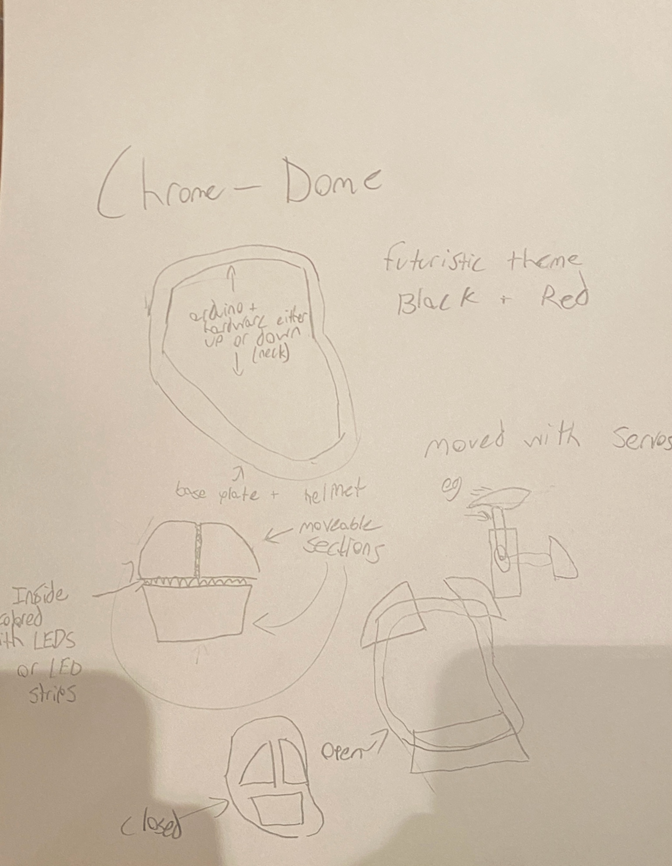
Chrome-Dome
MCU UNO, Nano DESIGN Lots of fusion 360, paint, maybe EasyEDA COMMUNICATION The uploaded sketch on the Nano or uno will trigger certain things when an input is given. This will be done without connections to a wall. MECHANICAL Servo motors for precise control an movement of the face-plate pieces |
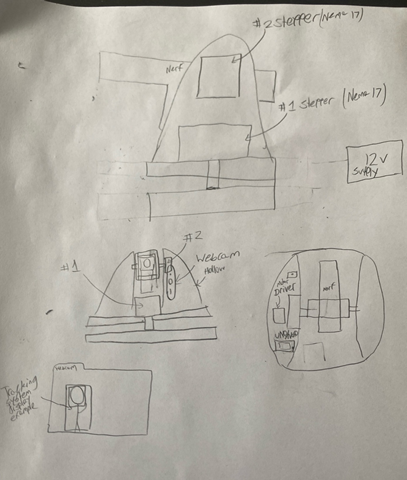
AI Sentry Turret
MCU 328p HARDWARE I will use two bipolar Nema-17 Stepper motors, an Arduino nano, two SN754410ne chips to control the stepper motors, the code will come from an Arduino and the camera tracking is through a webcam. SOFTWARE I will use python to track the target, an Arduino nano to control the stepper motors and “shoot” the target. DESIGN I will use Fusion 360 for the shell of the turret, I will use JLCPCB to house the stepper motor connections and the nanp MECHANICAL Stepper motors to control the different motions. COMMUNCATION I will use a standard USB cable to connect my Mac to the Arduino. I will use Serial Communication to connect python to the arduino |
Bertram M.
|
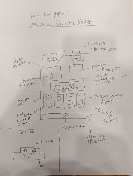
Ultrasonic Distance Meter
MCU None (CD: ?) DESIGN I will be using EasyEDA and Fusion360 to make a PCB and a case for the project. COMMUNICATION This project would not be using any software programming MECHANICAL N/A |
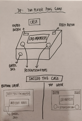
Two Player LED Matrix PONG game
MCU 328p HARDWARE The hardware portion of this project would mainly just consist of controlling the two LED matrices that are chained together with shift registers such as the 74HC595. There would also be two potentiometers which I would conduct analog read from to allow it to move a line of LEDs up and down the matrix. SOFTWARE I would first program a single lit up that constantly updates its position and moves only in a straight line. I would then make the code constantly check if the ball has bumped into the up, bottom, left edge, right edge, and both player 1 and 2’s platforms. If the ball hits the top or bottom of the led matrix, the x direction stays the same but the y direction is reversed and then continue to update the position of the ball, and if the ball hits either of the player’s platforms, the x direction is reversed and the y direction stays the same. If it hits the right or left side of the matrix, then the game ends. DESIGN The design would consist of two different circuit boards made by JLCPCB. One containing the Arduino nano along with the shift registers, the other containing the pot pins and the LED matrices and a custom case made on Fusion. MECHANICAL Potentiometer as paddles COMMUNCATION None |
Keaton M.
|
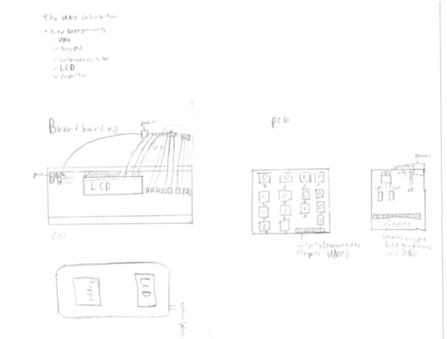
The UNO Calculator
MCU 328p (UNO) DESIGN I will use EasyEDA to produce a circuit board in which to emplace my power supply voltage regulator and necessary connections to the Uno keypad and LCD. The board will be streamlined and include silk screening clearly labeling each component and input/output. I will also use Fusion360 in order to create a user-friendly case with a slot for the PCB battery and an opening for the key pad and LCD. I will make a custom PCB for the key pad with silk screening labeling the use of each button. COMMUNICATION N/A MECHANICAL There are few details in this circuit which are Mechanical with the only main part being the voltage regulator which will translate 9V batteries into 5V there will also be a key pad which is wired to the UNO. |
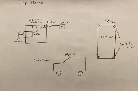
Mechanical mini-Car
MCU None HARDWARE The hardware details will be mainly motors powered by batteries. The circuit will first be wired on a breadboard and then a PCB will be connected to a case and the car. SOFTWARE None DESIGN the first design detail is a PCB which will be designed with EasyEDA and then shipped by JLCPCB. the PCB will potential be split into sections with mother boards or separate boards. The other design component is FUSION which will design the car and overall case. The car will be simple and not overly complicated, I plan to have sharp edges and an area to hold a PCB on the bottom. MECHANICAL There will be motors to power the wheels and these motors will be powered by batteries for the necessary power on the motors. COMMUNCATION None |
Rhys N.
|
Voltmeter
MCU None DESIGN EasyEDA and Fusion360 COMMUNICATION N/A MECHANICAL N/A |
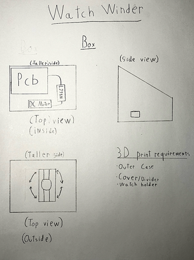
Watch Winder Box
MCU 328p HARDWARE There is a DC motor for rotation, and an Arduino Nano to control the motor's speed and timing, a motor driver (L298N), a power supply, a potentiometer to control rotation speed, and capacitors to limit noise. SOFTWARE The software for the watch winder project will be developed using the Arduino IDE to write and upload code to the Arduino Nano. The software will control the DC motor's speed, timing, and direction, to control rotation and make sure the motor operates well. The software will allow for precise control of the motor, including adjusting rotation speed and direction. DESIGN This project will use Fusion360 to develop the outer case, the watch holder and the various other small parts to cover the internal workings. JLCPCB will be used to create a PCB with the control features and to manage the DC motor. MECHANICAL DC Motor COMMUNCATION None |
Daniel O.
|
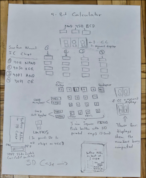
4-Bit Basic Calculator
MCU None DESIGN EasyEDA will be used when I am making my PCB as a permanent fixture for my 4-bit Basic Calculator and Fusion360 will be used for the designing of my case. COMMUNICATION N/A MECHANICAL N/A |
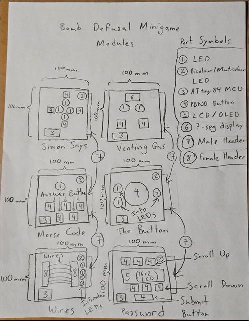
Bomb Defusing Minigame Modules
MCU ATtiny84 HARDWARE LEDs – To display colours/patterns PBNO Push Buttons – To input solutions to the minigames LCDs (or OLED replacement) – the screen used to display either numbers or characters SOFTWARE Tiny 84s – the MCU used to control each game. AVR Pocket Programmer – used to program the Tiny84 from Arduino IDE Arduino IDE – software used to program the Tiny 84 DESIGN EASYEDA/JLCPCB will be used to design the PCBs for each individual minigame MECHANICAL N/A COMMUNCATION N/A |
Jaoquin P.
|
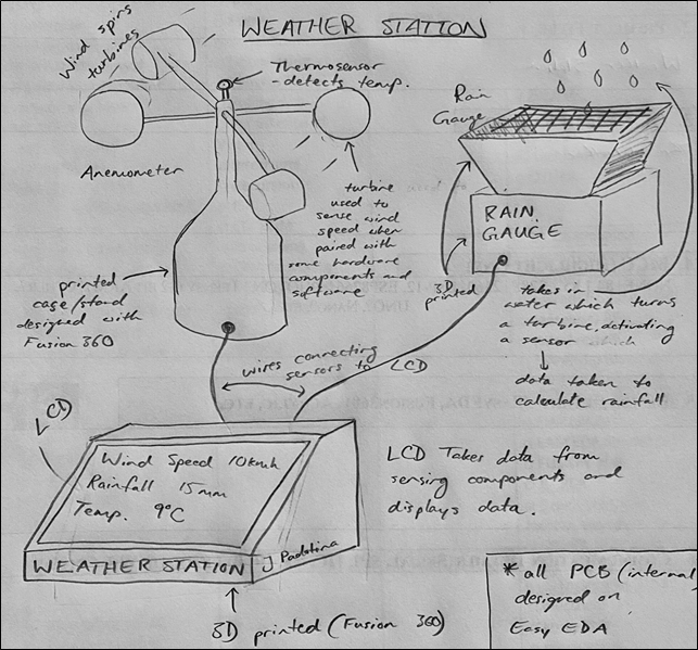
Weather Station
MCU 328p (Nano) DESIGN I will use EasyEDA to design the PCB(s) for my project. For the different external components and cases, I will use Fusion for the design. COMMUNICATION N/A (??) MECHANICAL N/A |
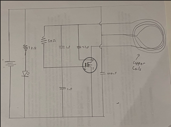
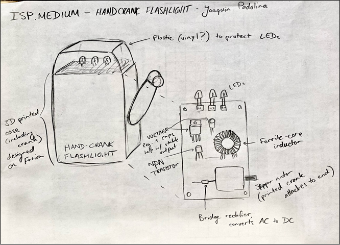
Hand Crank Flashlight
MCU None HARDWARE The circuit consists of two main parts: the generator, and the Joule Thief. The generator, allows for the conversion of mechanical energy to electrical energy using a stepper motor to generate an AC current, while a bridge rectifier converts AC current into DC. Schottky diodes prevent current from going back to the generator. The Joule thief consists of a ferrite-core inductor, along with a transistor. Capacitors and a voltage regulator make for a more reliable output. Finally, an LED(s) is powered, with a potentiometer to control the brightness. SOFTWARE No software is required, as the system relies purely on electronic circuitry and energy conversion principles to operate. DESIGN The case for the hand-crack flashlight will be designed using Fusion360’s design software. The PCB for this circuit will be designed using EasyEDA, then ordered through JCLPCB. MECHANICAL The dynamo generator for my circuit, will be a stepper motor. COMMUNCATION None |
Theo P.
|
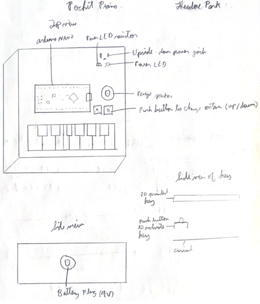
Pocket Piano
MCU 328p (Nano) DESIGN There will be use of EasyEDA as well as Fusion360. COMMUNICATION empty MECHANICAL I will be using a piezo speaker to emit the sound outputted from the piano. |
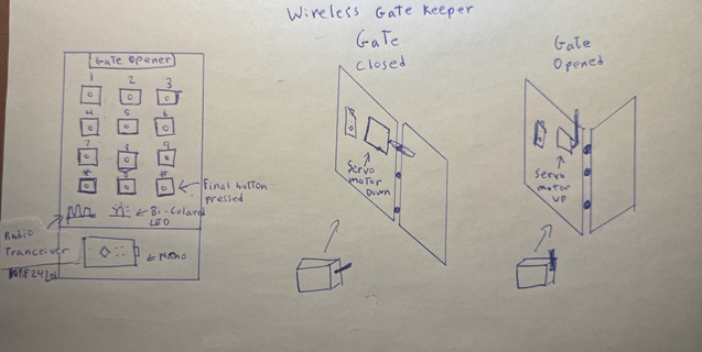
Wireless Gate Keeper
MCU 328p HARDWARE I will use the one-wire keypad concept by having multiple buttons connected to a single analog input pin, each producing a unique voltage when a button is pressed. A servo motor in this project controls the gate by rotating 90 degrees to open when the correct passcode is entered. SOFTWARE Radio communication in this project uses an RF transmitter and receiver to wirelessly send a signal indicating whether the entered passcode is correct or incorrect. DESIGN Two PCBs are being fabricated through JLCPCB—one for the receiver and one for the transmitter. I am also 3D printing the door and a custom case for the keypad in Fusion 360. MECHANICAL The project uses a servo motor to control the gate’s movement. COMMUNCATION RF, SPI, I2C |
Anka S.
|
Connect 4
MCU 328p (Nano) DESIGN The PCB will be made in EasyEDA and the case will be designed in Fusion360. COMMUNICATION N/A MECHANICAL N/A |
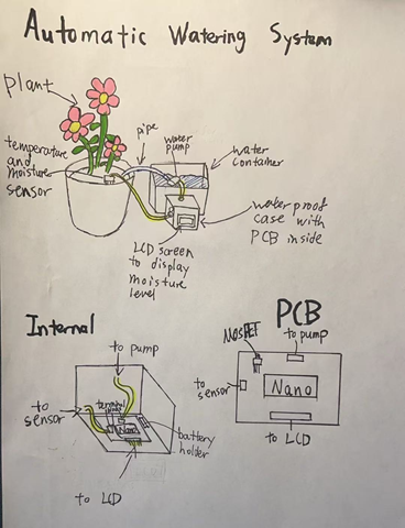
Automatic Water System
MCU 328p HARDWARE The battery will power the Arduino Nano, which will give signals to everything. There is a MOSFET for the Nano to be able to power the water pump. There are also terminal blocks to connect to the temperature and moisture sensor, the water pump, and the LCD screen. SOFTWARE The code is done in Arduino IDE since everything is driven by the Arduino Nano. The LiquidCrystal library is used to drive the LCD. DESIGN The PCB is designed and developed in EasyEDA and JLCPCB, while the case is designed in Fusion360. MECHANICAL A water pump will be driven by the Arduino Nano through a MOSFET. This will pump water from the container to the plant. COMMUNCATION None |
Jack S.
|
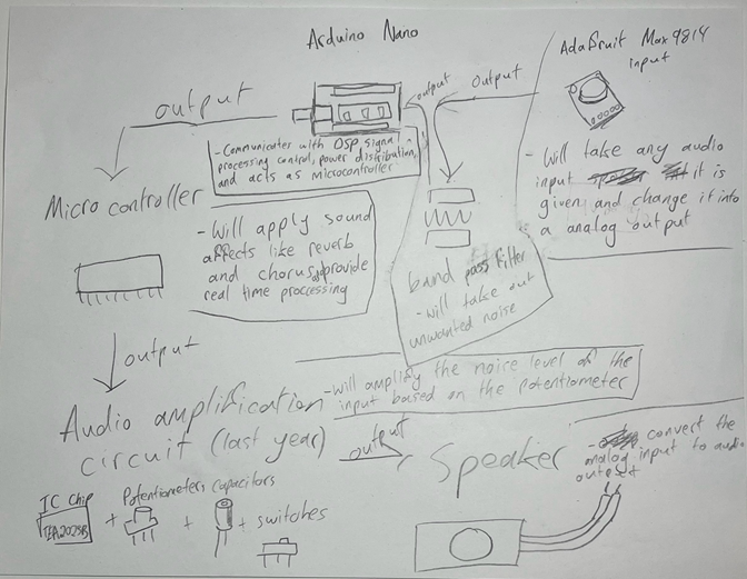
A real time audio processing device with effects
MCU 328p (Nano) DESIGN EasyEDA, Fusion 360 and JLCPCB COMMUNICATION N/A MECHANICAL N/A |
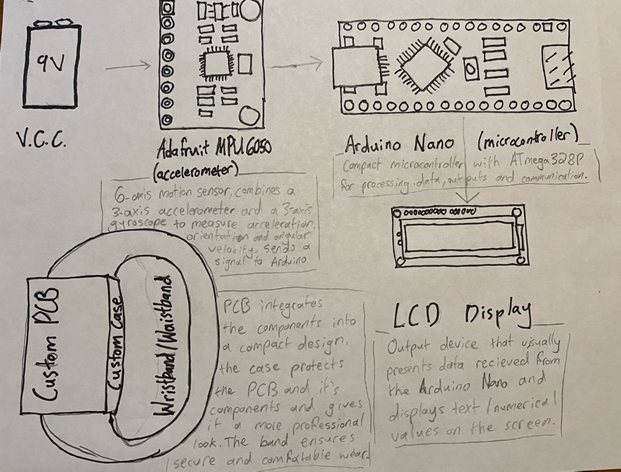
The Jump Height Tracker
MCU 328p HARDWARE This project will utilize several key components to receive the jump measurements. The MPU6050, accelerometer will be the primary sensor recording the data of the jump. The Arduino nano will then process this data and output it to an LCD screen. This system will also need components like resistors and capacitors for stable operation. Lastly, a 9V battery will be used to power the circuit. SOFTWARE An Arduino Nano and Arduino IDE will be used in this project to process the data detected by the accelerometer. Then within the C++ code, potential libraries will be used such as the MPU6050 Library or the LiquidCrystal_I2C. DESIGN EASYEDA, FUSION 360 AND JLCPCB MECHANICAL None COMMUNCATION I2C |
Jones T.
|
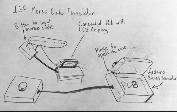
Morse Code Translator
MCU 328p (Nano) DESIGN EasyEDA PCB, Fusion360 Custom Case COMMUNICATION USB Data Transfer to Arduino Wire connections between the Button and Arduino, and between the Arduino and Screen. MECHANICAL There will be a hinge on both cases to open the case and see the internals. |
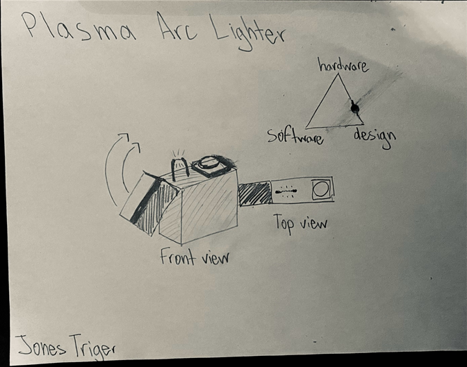
Plasma Arc Lighter
MCU None HARDWARE Lithium-Ion Battery, Boost Converter, High-Frequency Transformer, Push Button Switch, Custom PCB, Electrodes (for arc formation) SOFTWARE None DESIGN Fusion. EasyEDA MECHANICAL COMMUNCATION |
Nathaniel W.
|
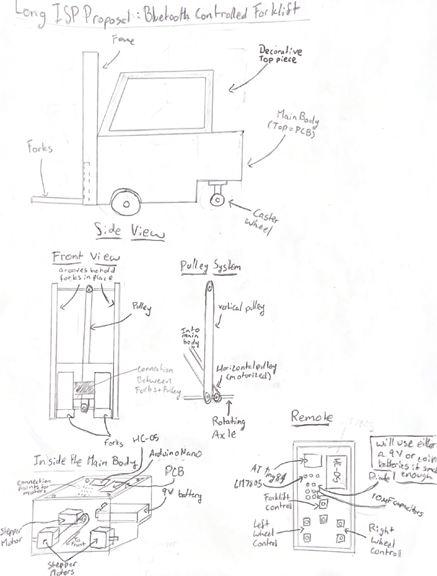
Bluetooth Controlled Forklift
MCU 84/328P (Nano) DESIGN The two PCBs for the vehicle and controller will be made in EasyEDA. All of the 3D design for the vehicle, controller encasement, and mechanical parts will be done in fusion. COMMUNICATION This project will use HC-05 modules to communicate with Bluetooth between the controller, which will have an ATtiny84 microcontroller, and the nano on the main body of the vehicle. MECHANICAL Three stepper motors will be used in the vehicle, one for each of the front wheels, which will be controlled independently, and one connected to the pulley which will move the forks up and down the front of the forklift. |
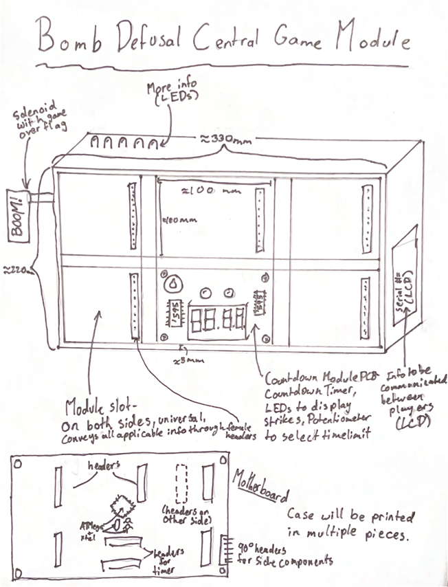
Bomb Defusal Central Game Module
MCU 328p HARDWARE The main module will be controlled by an ATMega328p, and the information scattered around the case will be displayed on LEDs and LCDs. The timer will use a 4-digit 7-segment display to display the countdown and two LEDs to display the strikes (only two are needed as on the third, the game ends.) The 4-digit display will be driven with 74HC595s. SOFTWARE The software for the central module will be fairly straightforward (although not easy), randomizing visual information at the beginning of the game and sending the information to each peripheral, then checking for strikes and completed modules while driving the countdown timer. DESIGN This case will be very large, and will have to be printed in 4 pieces due to some modules containing large components such as LCD screens. These pieces will be screwed together. There will be a supporting “back piece” for each module so that the headers can be on the right-hand side only, meaning that both sides of the case can have modules inserted. The case will be 3 modules across by 2 modules vertically on each side. MECHANICAL A solenoid will be used to push a flag out the side of the bomb that says “boom” for a funny payoff if the game is lost. COMMUNCATION All communication between modules will be done using GPIO communication |
William X.
|
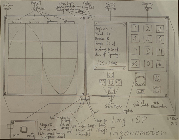
Trigonometer
MCU 2560 DESIGN EasyEDA will be used to create two custom PCB(s) (the circuit/prototype will be monstrous). Fusion 360 will be used to create one or two custom 3D printed case(s) (depending on the difficulty of the design that allows folding the case). COMMUNICATION The MAX7219 LED Matrix Modules and the TFT LCD will both use SPI interface. MECHANICAL The telephone keypad is the major mechanical component for this project. It will be used to inputs numbers and parameters for the equations of the functions. A joystick is used for creating a graph without inputting parameters (by dragging the joystick, the amplitude and the period of the customize graph can be adjusted). |
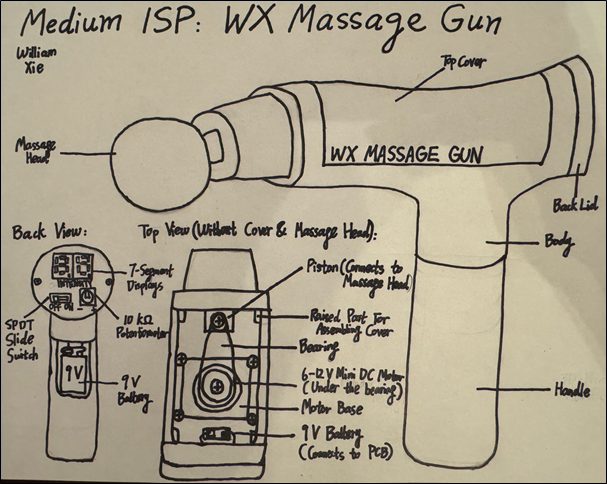
WX Massage Gun
MCU 328p HARDWARE The most important hardware component of this project is the 6-12 V mini DC motor used to generate the rotary motion to provide movements for the massage gun. Other hardware parts include an ATmega328p IC, a SPDT slide switch, an IRF520 MOSFET, a 10 kW potentiometer, two 7-segment displays, an LM7805 voltage regulator, a crystal, a diode, some resistors, and some capacitors. SOFTWARE Arduino C DESIGN One or two PCBs will be designed in EasyEDA depending on the final design of the body of the massage gun, and surface mount service will be ordered from JLC. The PCB at the back of the massage gun will be round. The body, handle, and the massage head of the massage gun will be designed in Fusion 360 and 3D printed. MECHANICAL A 6-12 V mini DC motor for the movements of the massage gun. COMMUNCATION None |


