2023-2024 ICS3U Independent Study Projects (ISPs) |
![]() Independent Study Projects. Please read our overview on why ACES pursue Independent Study Projects so vigorously.
Independent Study Projects. Please read our overview on why ACES pursue Independent Study Projects so vigorously.
| Grade | Contribution to Final Mark |
|---|---|
10 |
30% |
11 |
40% |
12 |
60% |
For the bulk of your formal education you have been, and will continue to be, required to consume curriculum chosen for you by someone else. Hopefully you will put this knowledge and skill to good use in your future. However, jumping through someone else's hoops no longer secures future success. For that, you must put yourself in the driver's seat while in secondary school to both cultivate and demonstrate your own unique initiative, motivation, and passion. RSGC ACES program is explicitly built and tailored for you to foster these greater goals. Yes, there is much to learn but there are so many great projects to be undertaken and noble problems to be identified and solved that offer stimulating contexts within which to develop and refine your interests it will quickly seem more than worth the risk, effort, and cost.

 To my mind, the characteristics of a great project include such aspects as imagination, creativity, a degree of risk and, sometimes, even simplicity, to name a few. Check out the flashlight circuit 'board' this guy made out of little more that a piece of paper and a pencil? Simple, but inspiring.
Consider a problem that needs a solution. Boyan Slat did at age 17 when he was in high school; four years later he is
To my mind, the characteristics of a great project include such aspects as imagination, creativity, a degree of risk and, sometimes, even simplicity, to name a few. Check out the flashlight circuit 'board' this guy made out of little more that a piece of paper and a pencil? Simple, but inspiring.
Consider a problem that needs a solution. Boyan Slat did at age 17 when he was in high school; four years later he is Also, don't underestimate the value of an enterprise/entrepreneurial aspect to your project that could see a number of units of your project in the hands of future ACES, for sale in the Dragon's Lair or beyond, reaching an even a broader audience.
2023-2024 Independent Study Projects
| ACE | Short ISP (20%) Saturday October 14 |
Medium ISP (20%) Saturday February 3 |
|---|---|---|
| Proposals | Short ISP Proposal |
Medium ISP Proposal |
| Evaluations | Short ISP Evaluation |
Medium ISP Evaluation |
Aiden A.
|
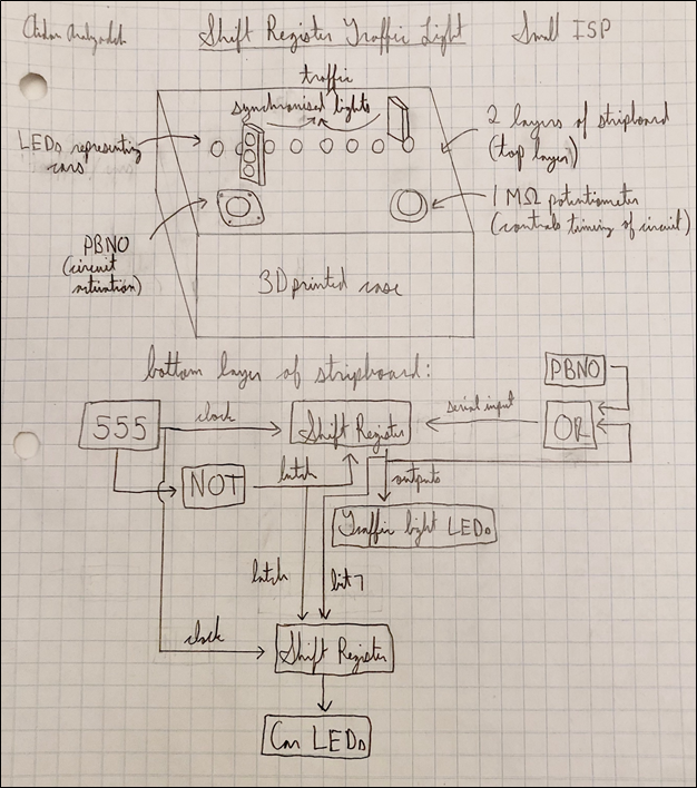
Shift Register Traffic Light
MCU N/A HARDWARE The 74HC595 shift registers are the main components of the circuit, with a 555 timer used for the clock inputs of the 595s and a 4071 OR gate for the serial input and a 4069 NOT gate for the latch input of one of the 595s. Transistors and passive devices such as LEDs, resistors, capacitors, potentiometer(s) and PBNO(s) are included in the project. SOFTWARE N/A DESIGN After a breadboarded prototype is constructed, Fusion 360 will be used to create a case for the project which houses the circuit on a stripboard. MECHANICAL N/A |
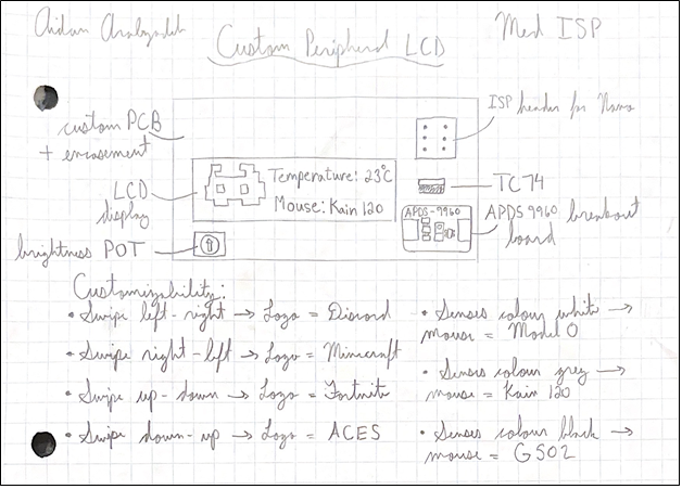
Custom Peripheral LCD
MCU 328P HARDWARE SOFTWARE DESIGN First a breadboard prototype is constructed, then the PCB is designed in EAGLE which connects the Nano, LCD, APDS9960, TC74, and potentiometer. Everything is housed in a 3D-printed case designed in Fusion360. MECHANICAL N/A COMMUNCATION There is Serial communication between the LCD and 328P and I2C communication between the APDS9960 and the temperature sensor and 328P. |
Camden A.
|
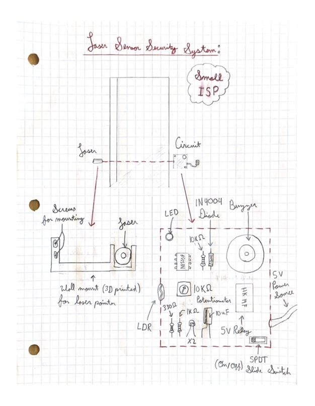
Laser Sensor Security System
MCU N/A HARDWARE NE555P Timer IC, Laser Pointer, Photocell LDR, HK19F 5 V Relay, 5 mm Red LED, Buzzer, 10 KΩ Potentiometer, 10 KΩ Resistor, 1 KΩ Resistor, 330 Ω Resistor, Electrolytic Capacitor 10 µF, (2) Ceramic Capacitor 0.1 µF, 1N4004 Diode, Stripboard, Jumper Wires, Fusion 360 Case for Circuit, Fusion 360 Laser Pointer Holder, 5 V DC Adapter 2A. SOFTWARE N/A DESIGN Stripboard, 3D Printing (mounting to the wall). MECHANICAL N/A |
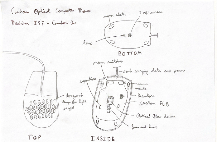
Custom Optical Computer Mouse
MCU 328P HARDWARE SOFTWARE DESIGN Fusion360, Custom EAGLE PCB printed by JLCPCB. MECHANICAL A scroll wheel might be implemented into the mouse design, depending if I have enough time and the difficulty level. COMMUNCATION SPI and Serial communication will be used to communicate from the mouse and sensor to the computer and vice-versa. |
Alex B.
|
Hexadecimal Decoder
MCU N/A HARDWARE 2 XOR IC logic chip 2NOR IC logic chip 1 OR IC logic chip 1 AND IC logic chip Rocker switches 7 segment display, Custom PCB Custom 3 printed Case. SOFTWARE N/A DESIGN I plan on starting by creating a breadboard prototype with a working Cricut. Once it is completed and working, I will transfer all the parts to a MECHANICAL N/A |
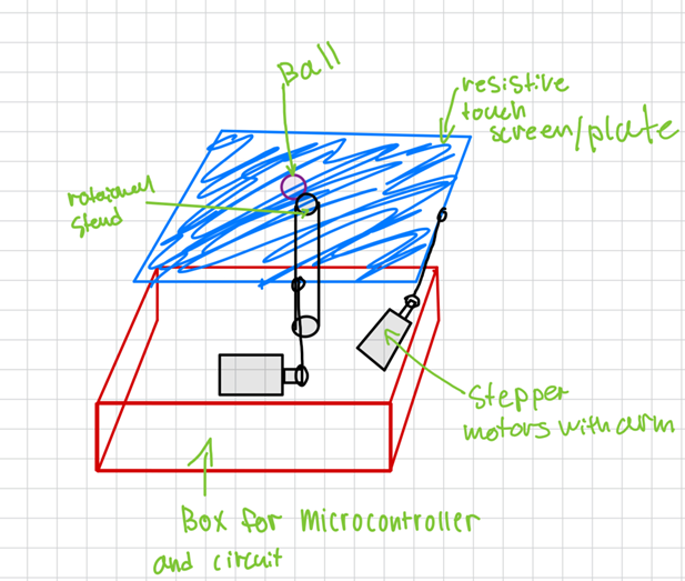
The Ball Balancer
MCU 328P HARDWARE SOFTWARE DESIGN The design part of this project plays a major role. A box will be designed to store the PCB, Arduino, and communication drivers. As well as arms for the stepper motors will be designed to attach to the platform. Lastly a universal joint will be used to hold up the platform so that it can rotate. MECHANICAL The location of the ball will be tracked through a resistive touch screen which will give x and y coordinates to where the ball must go in order to center. The platform will be tilted through the use of 2 stepper motors allowing for various angling of the platform. COMMUNICATION This device will communicate with the motor drivers through I2C connected to the Arduino and data coming from the resistive touch screen for the coordinates. The Arduino will be in control as the master device as the rest will be the slave devices. |
Nate C.
|
Jeopardy buzzer buttons
MCU N/A HARDWARE 555 Chip Push Buttons On and off switch Battery Buzzer SOFTWARE N/A DESIGN Stripboard, 3D Printing MECHANICAL N/A |
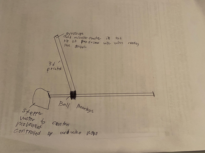
The Inverted Pendulum
DESCRIPTION This project aims to balance an upright rod (the pendulum) on a moving cart that slides along a
horizontal rail. To achieve this balance, the system dynamically adjusts the cart's position on the rail
in response to the pendulum's motion, countering gravitational forces that attempt to topple the
pendulum. The project's core components include stepper motors, a PID (Proportional-Integral-Derivative)
control library, and an IMU (Inertial Measurement Unit) sensor that combines an
accelerometer and gyroscope. |
Harsha G.
|
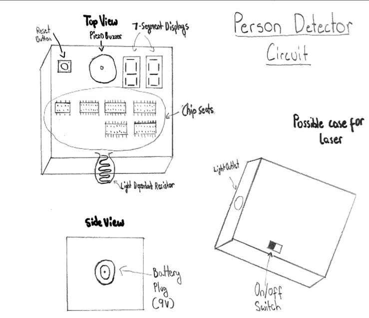
Person Detector Circuit
MCU N/A HARDWARE This project uses important hardware components such as a NE555 timer chip, a 4017-decade counter chip, a 4510 binary-coded decimal (BCD) up-down counter chip, a 4511 BCD, 7-segment displays, a 5V Piezo buzzer, and a LDR. SOFTWARE N/A DESIGN Will most likely be using a stripboard enclosed in a 3d printed case. MECHANICAL N/A |
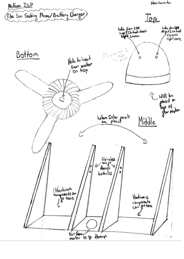
The Sun-Seeking Phone/Battery Charger
MCU 328P HARDWARE SOFTWARE DESIGN I will use FUSION360 to develop cases and a pcb for the circuitry. MECHANICAL A Gear Motor COMMUNICATION N/A |
Evan H.
|
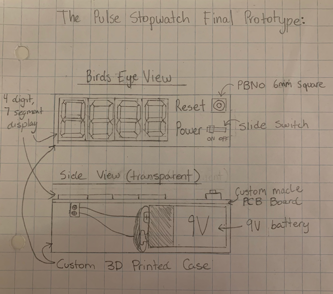
The Pulse Stopwatch
MCU N/A HARDWARE This project will utilize the 555 timer (configured for 1-second delay between outputs), PBNO buttons, a 9V battery, as well as some 4017 chips for the counter circuit. SOFTWARE N/A DESIGN The first version of this circuit will just simply be built on a breadboard. These versions will then slowly increase with complexity and resourcefulness, as the next version will be created on a stripboard as it allows more freedom within the soldering process. The V3 or final version of this prototype will be created using acrylic, a 3D printed case, MECHANICAL N/A |
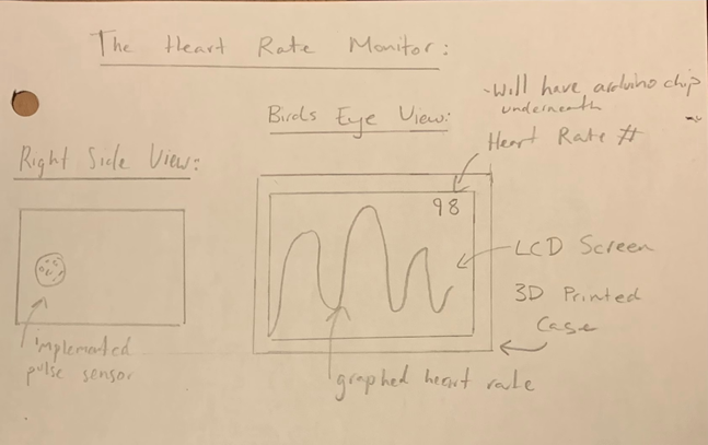
Heart Rate Monitor
MCU 328P HARDWARE SOFTWARE DESIGN The design of this project will be done using Fusion360 to create a comfortable 3D printed Case. This Case will either be a handheld version where the LCD screen and pulse sensor are placed next to each other or there will be a version that can strap to your wrist and be worn like a watch. In this version the pulse sensor will be strapped to your finger with the LCD being strapped to the wrist. MECHANICAL Only mechanical component used is the pulse sensor. The pulse sensor uses a infrared light and bounces in off the tip of the finger and uses the light that it receives back to determine heart rate/pulse. COMMUNICATION The heart rate monitor project will use Arduino programming to integrate a pulse sensor with an LCD screen. The code includes functions for updating the graph, and continuous data processing within the main system to ensure real time updating of the graph. This project will also most likely implement a library to help with plotting data and outputting to LCD. |
Chance H.
|
Wheatstone Thermometer
MCU 328P HARDWARE The project uses a 555 timer, a Thermistor, an ATmega328P microcontroller, an Arduino (most likely a Nano or Uno), and possibly an LCD. SOFTWARE Arduino C DESIGN The prototype of the circuit will be made on tinkercad along with the preliminary code for the microcontroller. The final product will most likely be an encased in a 3d printed case. MECHANICAL N/A |
Morse Code Translator
MCU 328P HARDWARE SOFTWARE DESIGN For this circuit a PCB will be used for the final product, the PCB will be designed using the EAGLE Software and housed in a 3d case, There will also be a 3d printed top lid so that only the screen and any interaction devices are visible to the user. MECHANICAL N/A COMMUNICATION To translate to Morse code the circuit will use user-input in the Serial Monitor to take a word and separate it into characters. Unfortunately, for the circuit to communicate with the serial monitor it will need to be directly connected to the laptop. This is not as portable as I would prefer for this device so if a better solution appears I will use that. |
Rohan J.
|
Custom Bike Speedometer
MCU 328P HARDWARE The main hardware component used in this project is an Atmega328P microcontroller chip. It will also need four different single-digit 7 segment displays, and four CMOS 4511 BCD decoder chips to go along with them in order decrease the required number of I/O pins. In this configuration, each display uses only 4 I/O pins instead of 7. SOFTWARE Arduino C DESIGN The device (made on a point-to-point/perf board) will be housed in a 3D printed case, barely larger than the size of the seven-segment displays (there will be multiple layers of boards to ensure a small footprint). The top layer will only include the four seven-segment displays, a switch to toggle between distance and speed and the appropriate header pins. The bottom layer will contain all the electronic components, including the 4511s (display drivers) the 328P, and others. Additionally, the device will be detachable from the bike via a second 3D printed part. The second part will mount directly (permanently) on the bike, and allow the main device to clip into it. It will also have male header pins that can interface with female header pins on the main device to allow the reed switch signal to pass through to the main device. The side of the case will have the power switch to turn off the device when inactive. MECHANICAL Magnetic Reed Switch |
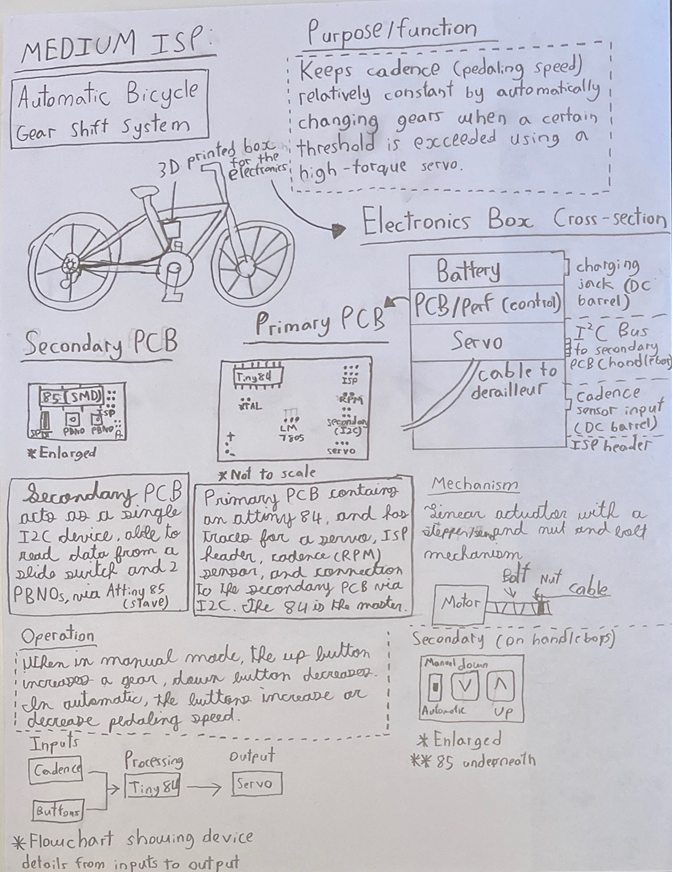
Automatic Bicycle Gear Shift System
MCU 84/85? HARDWARE SOFTWARE DESIGN The primary case is on the seat tube of the bike. It is 3d printed and secured with zip ties. It houses the motor assembly, primary board, and battery. The secondary case that is 3d printed is on the handlebars. it features a switch and 2 PBNOs. These are configured as a single I2C device using an Attiny85. This is mounted on a custom PCB, so that the MCU can be SMD to save as much space as possible. MECHANICAL The device will use a servo/stepper motor. Which one depends on how much rotation of the bolt is required. Additionally, there is a reed/magnet combo for the cadence sensor. COMMUNICATION To communicate between the handlebars controls and the primary PCB, an bus is employed. In this configuration, the Attiny85 is configured as the slave and allows the 2 buttons and the switch to be addressed as a single I2C device. The master is the ATtiny84. |
Jett K.
|
TMP36 Arduino Thermometer
MCU 328P HARDWARE The major components are a TMP36 temperature sensor, a 5V power supply, an Arduino Nano, an SPDT slide switch, and a 5mm LED. SOFTWARE Arduino C DESIGN The first prototype will be on a breadboard. Once I have figured out the circuitry and code I will then move to a perma-proto board with soldering. With the perma-proto I will 3d print a case for the final piece. MECHANICAL N/A |
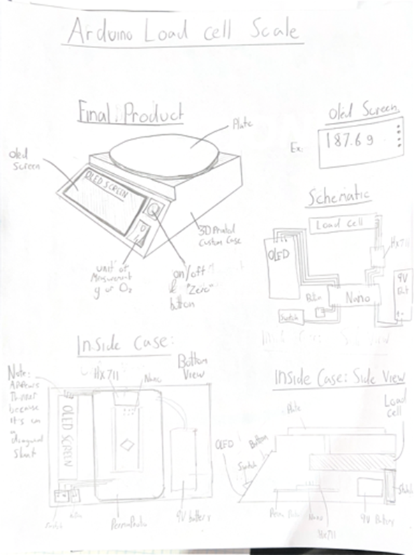
Arduino Load Cell Scale
MCU 328P HARDWARE 2kg Load Cell, HX711 Load Cell amplifier, Arduino Nano. SOFTWARE DESIGN The prototype will be built on a breadboard, Then I will transfer the final design to a perma-proto board. The entire build will be encased in a 3D print. I will also print a plate for objects to be measured on. MECHANICAL COMMUNICATION |
Triyan K.
|
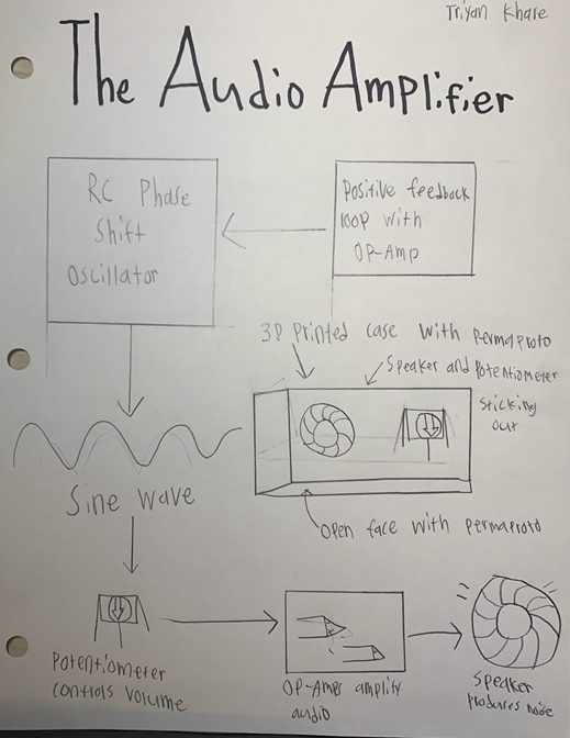
The Audio Amplifier
MCU N/A HARDWARE This project will involve Op-Amps which are intended specifically for audio applications. The sine wave oscillator will be in the form of an RC phase shift oscillator. Therefore, this project will require resistors, capacitors, jumper wires, a battery, a potentiometer, a speaker, diodes, and a transistor. SOFTWARE N/A DESIGN For this project, I will first create it on a breadboard, which will include all my components. After, I will solder all my components on a permaproto which will be encased in a 3D printed box using Fusion. In the final product, a potentiometer will be protruding from the case so that the audio output can be manually configured. There will also be a gap in the case to place my speaker. Additionally, the 3D printed box will have my initials on one side and the course code on the other. MECHANICAL N/A |
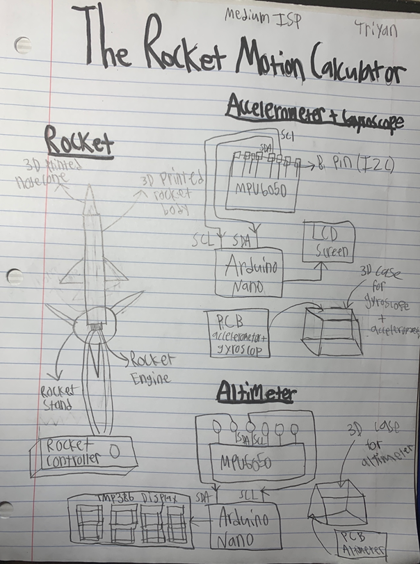
The Rocket Motion Calculator
MCU 328P HARDWARE SOFTWARE DESIGN To create the rocket, I will use Fusion 360. Since I want the rocket to be fairly large, I will print multiple components of the rocket and then hot glue them together. I will use EAGLE to create the PCB for both devices (MPU6050 IC with LCD screen) and (MPL3115A2 IC with seven segment display) in a 3D printed case made in Fusion. When I’m testing my rocket, I’ll use a perma-proto or perfboard to solder the components temporarily. MECHANICAL The project doesn’t really integrate any mechanical elements. Although, servo motors may be wired to the rocket’s fins to allow the rocket to liftoff more easily (maximizing its altitude). I will also use a rocket controller to activate the rocket engines, though this is store bought. COMMUNICATIONThe communication signal utilized will be I2C (Inter-integrated Communication) for all the peripheral devices. They will be wired to the Arduino Nano acting as the master. |
Rex L.
|
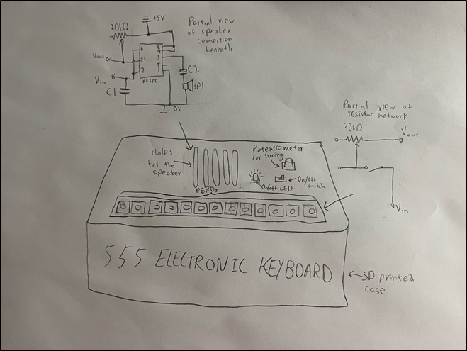
555 Electronic Keyboard
MCU N/A HARDWARE
SOFTWARE N/A DESIGN The circuit will be concealed in a 3D printed case utilizing a combination of permaproto and point-to-point boards. MECHANICAL Buttons as keys |
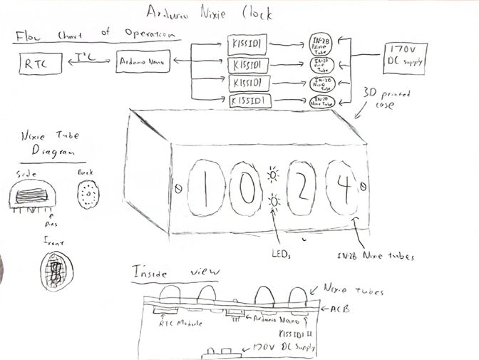
Arduino Nixie Clock
MCU 328P HARDWARE SOFTWARE DESIGN I will design a custom 3D-printed case for the circuit to be housed in. Potentially, there could also be a piece of custom cut acrylic covering the nixie tubes depending on the design of the case. MECHANICAL COMMUNICATION The RTC module of the circuit will use the I2C bus as communication between itself and the Arduino Nano. |
Oliver L.
|
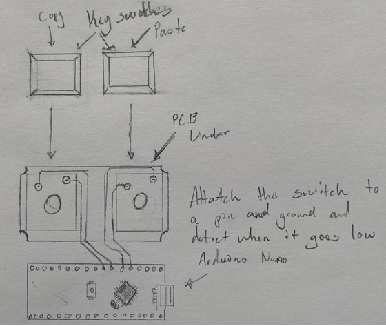
Copy&Paste Macro Keyboard (P1 of Stem Deck from Scratch)
MCU 328P HARDWARE Arduino Nano, Diodes, Resistors, and Custom PCB SOFTWARE Arduino C DESIGN I plan to first prototype this on a breadboard and once I get it complete and working, I will transfer and solder it onto a custom PCB with Eagle in a 3D printed case using Fusion 360. The PCB will be a custom 2x1 Keyboard PCB, Keyboard Switches will also be used. MECHANICAL N/A |
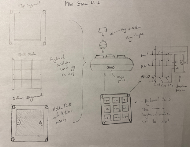
Mini Stream Deck (P2 of Stream Deck from Scratch)
MCU ATmega32u4 HARDWARE SOFTWARE DESIGN I will create a breadboard prototype of the keyboard matrix, then move it onto a custom 3x3 keyboard PCB designed on eagle, which will be held by a 3d printed case with rounded corners to give it a finished look. The case will be divided into three segments, the top segment which will be open, the plate which will separate the key switches from the PCB, and the bottom segment which will hold the PCB. MECHANICAL ? COMMUNICATION Serial communication between the Arduino Micro and the whatever Mac OS or Windows device you will be using. |
Lucas Q-T.
|
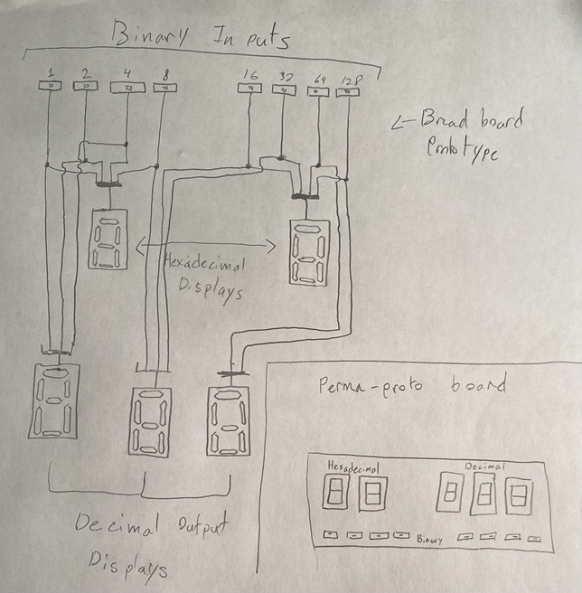
Digital to Hexadecimal Converter
MCU N/A HARDWARE 5 7 Segment Displays, 8 Slide Switches SOFTWARE N/A DESIGN BreadBoard, PermaProto MECHANICAL N/A |
The RC Robot
MCU 328P HARDWARE SOFTWARE DESIGN I will use Fusion 360 to design the case that will hold both the actual robot and the remote control. I will also use eagle to create the PCB in both the robot and remote. The remote will be designed to be both small and comfortable to hold will the addition of felt pads to make it softer. The robot will be designed to be as small and light as possible to reduce stress on the motors and make it as fast as possible MECHANICAL I will use 4 DC motors to control each wheel on the robot. COMMUNICATION This project will use Bluetooth for the remote and robot to talk to each other and so that the controller can control the robot remotely. |
Goran S.
|
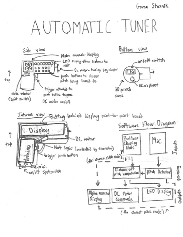
Automatic Tuner
MCU 328P HARDWARE This project involves an Arduino Nano, which will allow the device to hear the pitch via the microphone and create output commands on the DC motor to tune the pegs, and an alpha numeric display to show the pitch and LEDs the distance off. The alpha numeric display and LEDs will be soldered to a point-to-point board with inline resistors. The DC motor will be controlled by a push button trigger, which will make it so that only when the trigger is pushed, does the motor spin. SOFTWARE Arduino C DESIGN I will get the device working first on a breadboard, then it will move into a custom 3D printed case created using Fusion, which will be modeled around the components so that it forms a power drill-like shape. The alpha numeric display and LEDs will be visible from a side so the user can easily see what is happening. In addition to this, there is going to be a trigger button, which will enable or disable the DC motor from spinning. Finally, the part which attaches to the tuning pegs will be removable from the motor, so that it can be changed with other designs. MECHANICAL DC Motor |
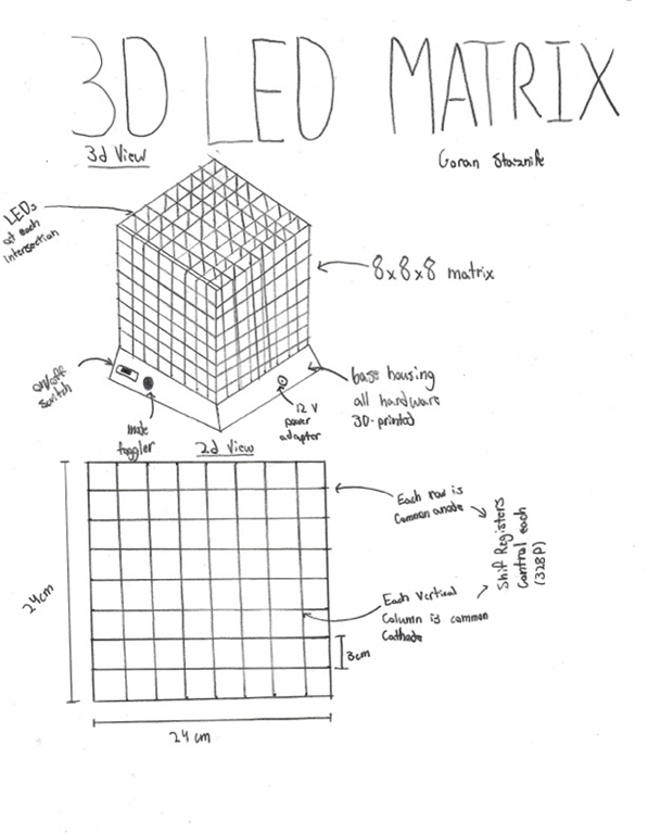
3D LED Cube
MCU 328P HARDWARE SOFTWARE DESIGN For the design of the Matrix, I will make the actual Matrix cube out of thin metal wires which are soldered together. Under the cube, there will be a base with a PCB. Around the PCB there will be a custom 3D-printed case to enclose it. MECHANICAL N/A COMMUNICATION I plan on using the SPI communication protocol to interface with the 328P chip that will control the MATRIX. |
Seb T.
|
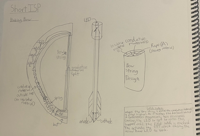
Blinking Bow
MCU N/A HARDWARE The main component is 555 IC chip. SOFTWARE N/A DESIGN The housing of the circuit will be half of a ¾ inch PVC Pipe bent in the shape of a bow. A spring will be placed inside with circuity on a PermaProto Board. MECHANICAL Sort of |
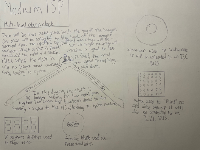
The Multi-Level Alarm Clock
DESCRIPTION This build will be an alarm clock system designed to wake you up. It will be similar to a normal alarm clock except for two main differences, that being how to turn off the alarm clock, and what will happen when the alarm clock goes off. To disarm the system, you must remove an article of clothing from a hanger. This will cause two metal strips to connect sending a Bluetooth signal to the MCU ending the sequence. The longer the system runs, the more intense the wake up methods will be. |
Atticus T.
|
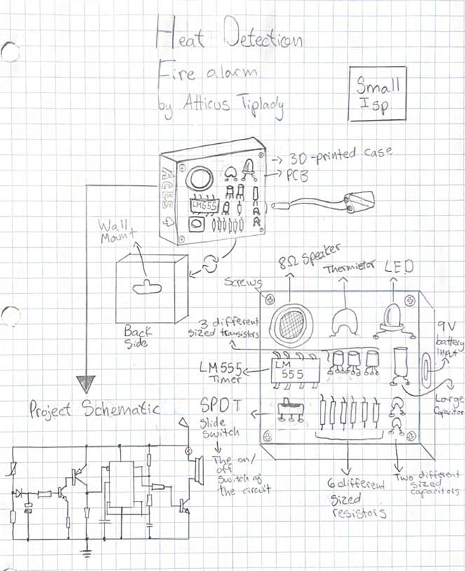
Heat Detection Fire Alarm
MCU N/A HARDWARE The major components that are utilized within my circuit is the LM555 Timer, a 10 KΩ Negative Temperature Coefficient Thermistor and an 8 Ω Speaker. SOFTWARE N/A DESIGN For the first prototype, I am building my circuit on a breadboard to figure out how the circuit works and mess with the layout to see where I can compress certain features. I will follow this by designing and soldering my circuit MECHANICAL N/A |
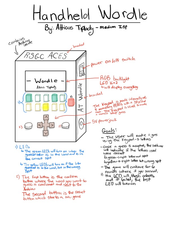
Handheld Wordle
MCU 328P HARDWARE SOFTWARE DESIGN I plan to create a PCB for my Handheld Wordle Game using EAGLE. This way, the soldering can be more transparent and concise, and an audience can differentiate what each solder's job is and what it accomplishes. Once the PCB has been properly created with the correct dimensions, I plan on designing and printing a case using Fusion 360 in the shape of a mini Gameboy. MECHANICAL N/A COMMUNICATION I plan to use communication when attaching the LCD to the Arduino Nano through the I2C. I am still deciding whether to attach it manually to my Arduino Nano or use the I2C bus, but if I do not attach the LCD screen directly, I will use the I2C bus another way.
|
Max Z.
|
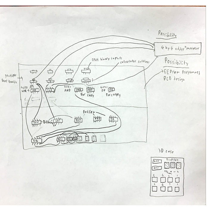
4-bit Calculator
MCU N/A HARDWARE 20 4081 CMOS chips, 20 4070 or 4030 CMOS chips, 10 4001 CMOS chips. SOFTWARE N/A DESIGN 3D Printed Case and Breadboard MECHANICAL N/A |
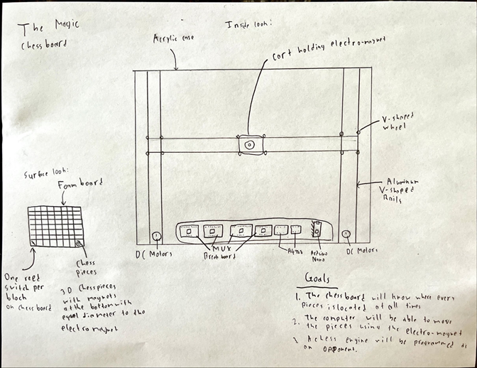
The Magic Chessboard
MCU 328P HARDWARE SOFTWARE DESIGN The design is a 450 by 125 mm rectangles for the acrylic sides and a 450 by 450 square top that is very compatible with magnets. MECHANICAL 2 Stepper motors controlled by A4988 Motor Driver Carriers. These are pulling a teethed rope. COMMUNICATION Serial communication is used on all devices through the Arduino Nano. There is a possibility of including an I2C compatible LCD screen to display the position. |


