| 2018-2019 ICS3U Engineering Tasks |
![]() ACES' Choice: Raymond RTC Appliance or the Matrix Equalizer Stick. For your second-to-last project of the year, you have 10 days (and 3 work periods) to put together another legacy device. Two aspects of this project that separate it from most others are,
ACES' Choice: Raymond RTC Appliance or the Matrix Equalizer Stick. For your second-to-last project of the year, you have 10 days (and 3 work periods) to put together another legacy device. Two aspects of this project that separate it from most others are,
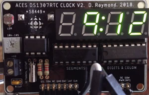
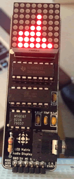
The Raymond RTC Appliance is a legacy PCB concept developed by D. Raymond (ACES '19) for use by ACES as a UNO Appliance based on the DS1307 RTC (kind of like your own personal Gecko) The Matrix Equalizer Stick is a compact PCB designed for use by ACES to confirm their mastery over the MSGEQ7 Spectrum Analyzer and 8x8 Matrix POV coding techniques.
| ACES' Choice | |
|---|---|
| Raymond RTC Appliance (ATmega328p) | Matrix Equalizer Stick (ATtiny84) |
 |
 |
| ACESRTCApplianceRaymondv2.sch ACESRTCApplianceRaymondv2.brd |
MatrixEqualizer.sch MatrixEqualizer.brd |
| RC, ZK, OM, SP, NV, FW, NW | DB, BD, JD, FF, JL, LM, CM, MM, JP, EP, AR, LW |
Task.
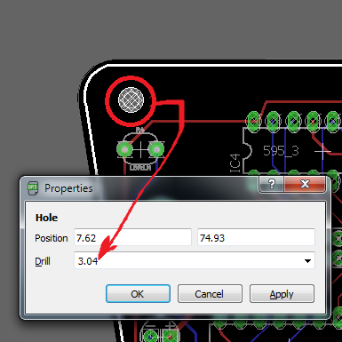
 Create EAGLE Projects from the .sch and .brd files I have supplied and look at them carefully. This will give you insight into the software that you (or your team if you are one to rely on others) must develop as shift registers form the backbone of both devices. Furthermore you may wish to modify one (or both - even a combo?) for your own purposes and have PCBs manufactured. The Matrix Equalizer Stick, for example, uses a Line In Jack for your AUX cable where you prefer to adapt it for use with a microphone.
![]() Legacy PCB/Appliance. ACES' Alumni continue to contribute to our program through their former achievements. PB machines, Schaffer Traffic Lights, Morland Bargraphs, Reed MatrixMadeEZs, Logush nRFBreakout, and Raymond RTCs were all straightforward but brilliantly conceived devices that are instrumental in support of our current learning. Take a look through our online archive of ACES PCBs for inspiration.
Legacy PCB/Appliance. ACES' Alumni continue to contribute to our program through their former achievements. PB machines, Schaffer Traffic Lights, Morland Bargraphs, Reed MatrixMadeEZs, Logush nRFBreakout, and Raymond RTCs were all straightforward but brilliantly conceived devices that are instrumental in support of our current learning. Take a look through our online archive of ACES PCBs for inspiration.
To further strengthen your printed circuit board design skills and to give you an opportunity to leave your mark on RSGC's ACES program, you are tasked with the opportunity and challenge of imagining and designing a board that YOU feel would have made YOUR study of electronics a richer (and more time-efficient) experience. The best projects are simple, replace a single task you do over and over, and can be put together with a few handy parts. For my part I have created and continue to maintain a library of common THT parts we use in the DES all the time. Download the library ACES_THT.lbr and use it in your projects.
A few notable considerations to inspire your own creation in include the following,
Tasks
Part 1. Due Wednesday April 10 @ START of class
 You've thought deeply about a simple PCB/Appliance that would have made a previous project you undertook either easier, or richer.
Part 2. Due Saturday April 13.
I will take one or more of the BEST creations, adapt them for use in next year's courses and make you famous in the process. Good luck.
![]() Project 6. ACES Rover. This will one of the most demanding projects our ACES program will present you with. What you do with the opportunity (like all others) is completely up to you. You can sit back and let your team members carry you through to the final report or you can hold your head high in March knowing that the success of your group was due in no small measure to the skill and dedication you poured into it over two months.
Project 6. ACES Rover. This will one of the most demanding projects our ACES program will present you with. What you do with the opportunity (like all others) is completely up to you. You can sit back and let your team members carry you through to the final report or you can hold your head high in March knowing that the success of your group was due in no small measure to the skill and dedication you poured into it over two months.
Project Description: DesignEngineeringProject.docx
| Competition Day: March 5, 2019 | |
|---|---|
| The Engineers | The Course (NW) |
 |
 |
| Additional Photos: https://drive.google.com/drive/folders/1g0tXiAUSEAq-tPXaBmX0XjqAsCBWKQyz | |
In Class Development Sessions:
Battery Considerations
Five Deadlines
If we hope to bring this project to a successful conclusion, leaders must maintain and file their team's updated Gantt Chart, weekly.
| On Time | Late | No Show |
|---|
| Team | 01 19 | 01 26 | 02 02 | 02 09 | 02 16 | 02 23 | Total |
|---|---|---|---|---|---|---|---|
| Red Army | 4/6 | ||||||
| SS Goofballs | 2/6 | ||||||
| 11:59ers | 4.5/6 | ||||||
| Pros | 5/6 | ||||||
| Dregnauts | 3.5/6 | ||||||
| ACES of ♠ | 3/6 |
Supplied Materials (that need to be returned)
Analog Devices: 'Drive 360' Autonomous Driving Sensing Products
Teams:
| Design Engineering Project: ACES ROVER | ||||||||||
|---|---|---|---|---|---|---|---|---|---|---|
| TEAM | MEMBERS and DOMAINS | CATEGORY EVALUATIONS | ||||||||
| NAME | LEADER | Design | Hardware | Software | Design | Hardware | Software | Time | RANK | Score** |
| Red Army | Pyper | Pyper | Macdonald | Mazzuca | 5 | 9 | 4 | 1 | 16 | |
| SS Goofballs | McFarlane | Kingsley | McFarlane | Wilkinson | 7 | 7 | 4 | 2 | 15 | |
| 11:59ers | Watson | McCutcheon | Parker | Watson | 5 | 9 | 4 | 3 | 14 | |
| Pros* | Fatola | Vassos | Fatola | Rigby | 6 | 7 | 5 | 4 | 13 | |
| Dregnauts* | Carson | Dreger | Carson | Barkway | 6 | 6 | 6 | 5 | 12 | |
| ACES of ♠* | Peterson | Dolgin | Lank | Peterson | 6 | 7 | 5 | 6 | 11 | |
* Fits Original Criteria, ** Score out of 15
| ACE | 1 | 2 | 3 |
|---|---|---|---|
Barkway, D. |
S | H | D |
Carson, R. |
H | D | S |
Dolgin, J. |
D | H | S |
Dreger, B. |
D | S | H |
Fatola, F. |
H | S | D |
Kingsley, Z. |
D | H | S |
Lank, J. |
H | D | S |
Macdonald, C. |
H | D | S |
Mazzuca, L. |
H | S | D |
McCutcheon, M. |
H | D | S |
McFarlane, O. |
D | H | S |
Parker, J. |
H | D | S |
Peterson, S. |
S | H | D |
Pyper, E. |
H | D | S |
Rigby, A. |
S | H | D |
Vassos, N. |
D | H | S |
Watson, L. |
H | S | D |
Wilkinson, F. |
H | S | D |
Woollcombe, N. |
Course Designer | ||
![]() Project 5. Design Sessions. Your final ER prior to Christmas is to include a comprehesive review of your introductions to EAGLE and ViaCAD. Under Heading 2 styles (either EAGLE of ViaCAD) in the order you explored each application, document your three design classes within the section subheadings: Purpose, Procedure, Media and Reflection. You are NOT required to make a video for this Report, but the text and graphic support will be, as I mentioned, comprehensive. Here are the design projects each group was asked to develop,
Project 5. Design Sessions. Your final ER prior to Christmas is to include a comprehesive review of your introductions to EAGLE and ViaCAD. Under Heading 2 styles (either EAGLE of ViaCAD) in the order you explored each application, document your three design classes within the section subheadings: Purpose, Procedure, Media and Reflection. You are NOT required to make a video for this Report, but the text and graphic support will be, as I mentioned, comprehensive. Here are the design projects each group was asked to develop,
| Session 1 | |
|---|---|
| EAGLE | ViaCAD |
| 7-Segment Tester | HC-SR04 Mounting Bracket |
| Session 2 | |
| EAGLE | ViaCAD |
| H-Bridge Motor Shield | Stepper Motor Mount |
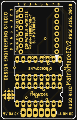
![]() Project 4. MatrixMadeEZ. For his PCB project in Grade 11, Hugo R. (ACES '19) imagined, designed, and developed a handy PCB that future Grade 11s could exploit to hone their LED matrix software animation skills. We're going to incorporate Hugo's terrific little device into an ambitious standalone project. To assist with your time-management pursuits, I'm strongly suggesting you discipline yourself to stick to the timeline below to enable a successful conclusion two weeks from now, on Saturday November 17.
Project 4. MatrixMadeEZ. For his PCB project in Grade 11, Hugo R. (ACES '19) imagined, designed, and developed a handy PCB that future Grade 11s could exploit to hone their LED matrix software animation skills. We're going to incorporate Hugo's terrific little device into an ambitious standalone project. To assist with your time-management pursuits, I'm strongly suggesting you discipline yourself to stick to the timeline below to enable a successful conclusion two weeks from now, on Saturday November 17.
Task
Parts List for Hugo R.'s MatrixMadeEZ PCB,
The 6-pin right-angle male header will allow your device to be mounted vertically in your breadboard, driven by your standalone Arduino. Make Hugo proud.
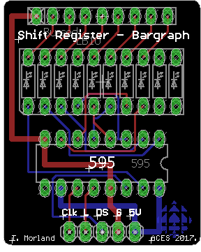
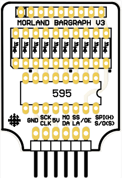
![]() Project 3. Shift Register - Bargraph. When Tim Morland (ACES '18, Queen's Eng '22) was in Grade 11, he designed the adjacent output PCB based on the 595 Shift Register and a bargraph. Your toolkit contains the SN74HC595 IC, a 16-pin IC Socket, and a 10-LED red bargraph. The remaining parts, a 5-pin right angle male header, 330Ω 8-pin bussed resistor network, and Tim's PCB, will be provided to you.
Project 3. Shift Register - Bargraph. When Tim Morland (ACES '18, Queen's Eng '22) was in Grade 11, he designed the adjacent output PCB based on the 595 Shift Register and a bargraph. Your toolkit contains the SN74HC595 IC, a 16-pin IC Socket, and a 10-LED red bargraph. The remaining parts, a 5-pin right angle male header, 330Ω 8-pin bussed resistor network, and Tim's PCB, will be provided to you.
You are asked to create a unique and interesting prototype that employs Tim's Shift Register-Bargraph output device.
In addition, just as James Lank dipped into his toolbox and incorporated the LCD screen into his previous ASCII & Buttons project because he was intrigued to discover its potential, each of you is required to do the same. Identify a part you have never previously used and combine it with this Shift Register-Bargraph output device in a meaningful way.
Finally, one shortcoming of this device is that there are 10 LEDs in the bargraph but only 8 outputs provided by the onboard '595 shift register. It's kind of like a packs of hot dogs are sold in dozens but the buns, in packs of eight. This is not good but it clearly presents an opportunity for the creative amongst you.
Your mark will be based largely on how creative and how DIFFERENT yours is from everyone else's and how potentially USEFUL your application could be. Give it some deep thought and push yourself hard your efforts could possibly form the basis for a future ISP. I'm looking for trailblazers this weekend, not followers.
Again, ![]() for the engineering and
for the engineering and ![]() for the unique design and creativity.
for the unique design and creativity.
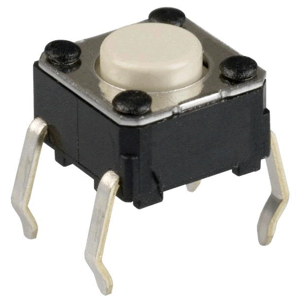
![]() Project 2. ASCII & Buttons. Time to let the horses run. We've reviewed the Arduino's recognition of the ASCII characters and it's ability to read (properly conditioned) button input. For your second project I want your imagination to take center stage in the pursuit of a creative application involving button presses, ASCII characters, some form of manipulation/processing of the two, and its display.
Project 2. ASCII & Buttons. Time to let the horses run. We've reviewed the Arduino's recognition of the ASCII characters and it's ability to read (properly conditioned) button input. For your second project I want your imagination to take center stage in the pursuit of a creative application involving button presses, ASCII characters, some form of manipulation/processing of the two, and its display.
 |
 |
The ![]() -rating of this project is based on
-rating of this project is based on ![]() for the engineering and
for the engineering and ![]() for the unique creativity your project will project (how's that for phrasing!). Standard ER sections apply with heightenend awareness of the video constraints now in effect (no music, stable camera and components, no spelling errors in the video titling, and not too many Persian carpet backgrounds)
for the unique creativity your project will project (how's that for phrasing!). Standard ER sections apply with heightenend awareness of the video constraints now in effect (no music, stable camera and components, no spelling errors in the video titling, and not too many Persian carpet backgrounds)
![]() Project 1. Traffic Light Assembly and Testing. Make the following updates to your ER,
Project 1. Traffic Light Assembly and Testing. Make the following updates to your ER,
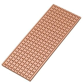
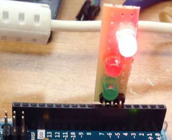
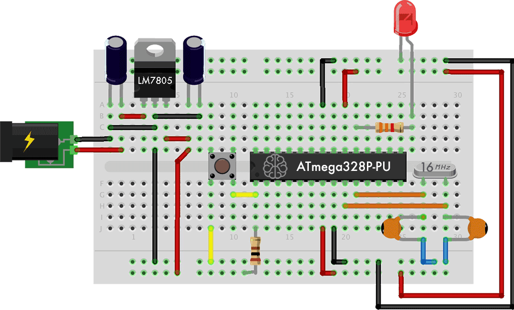
 Since many of you will be pursuing your driver's license in the near future, the focus of this first summary is the design, careful soldering, programming and thorough testing of a Traffic Light. For the assembly aspect of this project you will solder one each of a green, yellow, and red LEDs onto the section of stripboard you have been provided with. NOTE: The stripboard only has three strips. The placement and orientation of the LEDS is tricky and you must give it some DEEP THOUGHT if you're going to be able to program it so it operates correctly. Take care as there are NO replacement parts. A three-pin right-angle header, soldered at one end, will enable your device to be inserted directly into your Arduino's female port pins (see photo) Be sure to document your soldering of the device through media acquisition that you can include in your report. For the testing aspect, you will include media as well as a simple sketch based on our discussions in class. The fully documented sketch should cycle through the LEDs continuously with the green and red remaining on for 3 s and the yellow, 1 s.
In your report, include the sections Purpose, Reference, Procedure, Code, Media, and Reflection Heading 2 (or 3) style. A full Parts Table should appear right-aligned within the Procedure section.
| Stripboard | Example |
|---|---|
 |
 |