| 2017-2018 TEI3M Engineering Tasks |
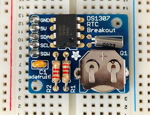
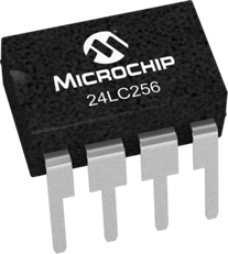
![]() I2C Data Logger. This project requires that you capture (multiple) sensor data over a period of time and log it with the Time/Date stamp from an I2C-compatible Real-Time Clock, to a I2C-compatible 256K EEPROM IC. The expectations for the project include a high build quality from the circuit itself to the encasement and access points. Finally, the data collected is to be displayed using a creative form of visualization. This presentation can be in Processing, a connectable graphics screen, Excel, or any other form of graphic depiction.
I2C Data Logger. This project requires that you capture (multiple) sensor data over a period of time and log it with the Time/Date stamp from an I2C-compatible Real-Time Clock, to a I2C-compatible 256K EEPROM IC. The expectations for the project include a high build quality from the circuit itself to the encasement and access points. Finally, the data collected is to be displayed using a creative form of visualization. This presentation can be in Processing, a connectable graphics screen, Excel, or any other form of graphic depiction.
There are a wide variety of analog sensors on the market as well as I2C sensors. The sooner you identify the concept/data you wish to log, the more time you'll have to secure an I2C sensor(s). Think creatively, simple monitoring of room temperature would demonstrate the least amount of imagination. On the other hand, a recent or upcoming lab from one of your science courses might be the perfect opportunity to apply sensor monitoring to. The Science department may even have their own sensing devices that you could interface with...
Some of the best projects will be based on a concept, principle, law, or research the engineer sets out to try to confirm or refute.
Design Considerations. In addition to CODE design decisions you make along the way as you develop your sketchs, this project requires that you make DATA design decisions as well. The use of the finite, byte- and page-oriented Serial EEPROM IC requires that you give deep consideration to the organization and design of the data you store for later retrieval. You are aware that the time and date data from the RTC is already in byte form, whereas the ADC data from analog read appears as two-byte ints [0-1024).
Note. You will present your work to your peers. In addition, this project will have a competitive side as each student will rank the other 19 projects in order of creativity, performance, build quality, etc. I'll aggregate the result and assign credit in relation to the results. Here is the evaluation page that will be used.
ER summary due Tuesday May 3 under the Subject Line: I2C Data Logger.
| I2C DS1307 RTC | I2C 24LC256 EEPROM | Sensors |
|---|---|---|
 |
 |
 |
![]() Medium ISP. See Description.
Medium ISP. See Description.
![]() Design Skill 2. Printed Circuit Board
Design Skill 2. Printed Circuit Board
 The goal of this project is two-fold. The first is familiarize yourself with the complete PCB cycle from conception, design, implementation, outsourcing, soldering and testing. The second is to leave a legacy so that those that follow you can benefit directly from your creativity and skill, just as you have from those that have gone before you.
PCB1. Design and Ordering
After settling in on a board concept that you think would be have been highly useful to your study of electronics to this point, you are asked to design the PCB, zip up the necessary files and perform a practice ordering and outsourcing of your project to DirtyPCBs. You will practice ordering a Protopack. What I like about DirtyPCBs is that, at the moment of ordering, the service supplies you with an immediate rendering of your design. You will take a screen capture of the image and, along with screen captures of the EAGLE Schematic and Board views of your design, you have plenty of content to assemble the first part of an ER entry for this project. You can also assemble and include a Parts List required to popluate one board. To save shipping costs have your files with you in class on Monday April 9 and we'll place a group order before the end of the period. Submit your ER by the deadline under the Subject line indicated.
 PCB2. Assembly and Reporting
Upon receipt of your boards you are required to solder the components to the board, test it and insert it into a circuit context that fully demonstrates its capabilities. Video footage of the assembly and functioning of your device device is to be captured and linked from the second part of this report. Resubmit your ER by the deadline under the Subject line indicated.
PCB3. Presentation and Voting
OK, it's time to convince your peers of your creative briliance and immaculate execution skills. Prepare a short (5-minute) presentation that convinces the audience of the need and value of going back to DirtyPCBs and ordering a class set of your boards for use in the ACES program next year.
After the 10 presentations, you'll leave the boards wih me and rank the boards for the 3-2-1 year-end bonus. I'll also have the Senior ACES weigh in on the merits of your boards. Good luck.
![]() Short ISP. See Description.
Short ISP. See Description.
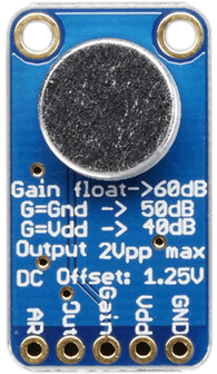
![]() Frequency Spectrum Analyzer. As the title suggests you are to develop a device capable of receiving an audio signal (microphone and/or 3.5mm line in jack ) analyzing/splitting the signal into 7 different frequency bands (MSGEQ7) and displaying the levels in some manner,
Frequency Spectrum Analyzer. As the title suggests you are to develop a device capable of receiving an audio signal (microphone and/or 3.5mm line in jack ) analyzing/splitting the signal into 7 different frequency bands (MSGEQ7) and displaying the levels in some manner,
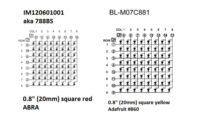
![]() Day 1. ATtiny84 Stable Display on your 0.8" LED Matrix
Day 1. ATtiny84 Stable Display on your 0.8" LED Matrix
uint8_t spectrum [7] = {0x01,0x03,...};
Day 2. ATtiny84 Dynamic Display with Dual Inputs (Line In and Electret Microphone) and MSGEQ7
 Review this description of 3.5mm TRRS audio jacks from http://www.cablechick.com.au
 both and confirm BOTH audio input devices. Use your SPDT slide switch to switch inputs from one to the other. This online frequency generator can be used to test and confirm each of the seven frequency bands.
Day 3. Device Commitment (For the future...)
 We have suggested/introduced/explored a number of concepts and components you are encouraged to align your interest and research with. These include,
Submit to handin by midnight, Saturday February 24. with the Subject Line: Frequency Spectrum Analyzer.
You will have a few minutes to present your project to your peers on Monday February 26.
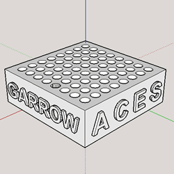
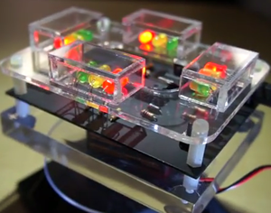
![]() DIY Bicolor LED Display. in the spring of 2014, T. Garrow (ACES '15) asked me what he could design and render on the 3D printer he received for Christmas. I suggested a double-sided jig that ACES could use to fabricate their own LED matrix and he did just that! A class set of on-site printed jigs was impractical as the print time for a single one exceeds 2 hours. Fortunately, a company stepped in (Objex Unlimited) and printed two dozen for us in the spring of 2017, so the project became a reality.
DIY Bicolor LED Display. in the spring of 2014, T. Garrow (ACES '15) asked me what he could design and render on the 3D printer he received for Christmas. I suggested a double-sided jig that ACES could use to fabricate their own LED matrix and he did just that! A class set of on-site printed jigs was impractical as the print time for a single one exceeds 2 hours. Fortunately, a company stepped in (Objex Unlimited) and printed two dozen for us in the spring of 2017, so the project became a reality.
| Matrix Jig (T. Garrow, ACES '15) | Partially Assembled BiColor LED Matrix |
|---|---|
 |
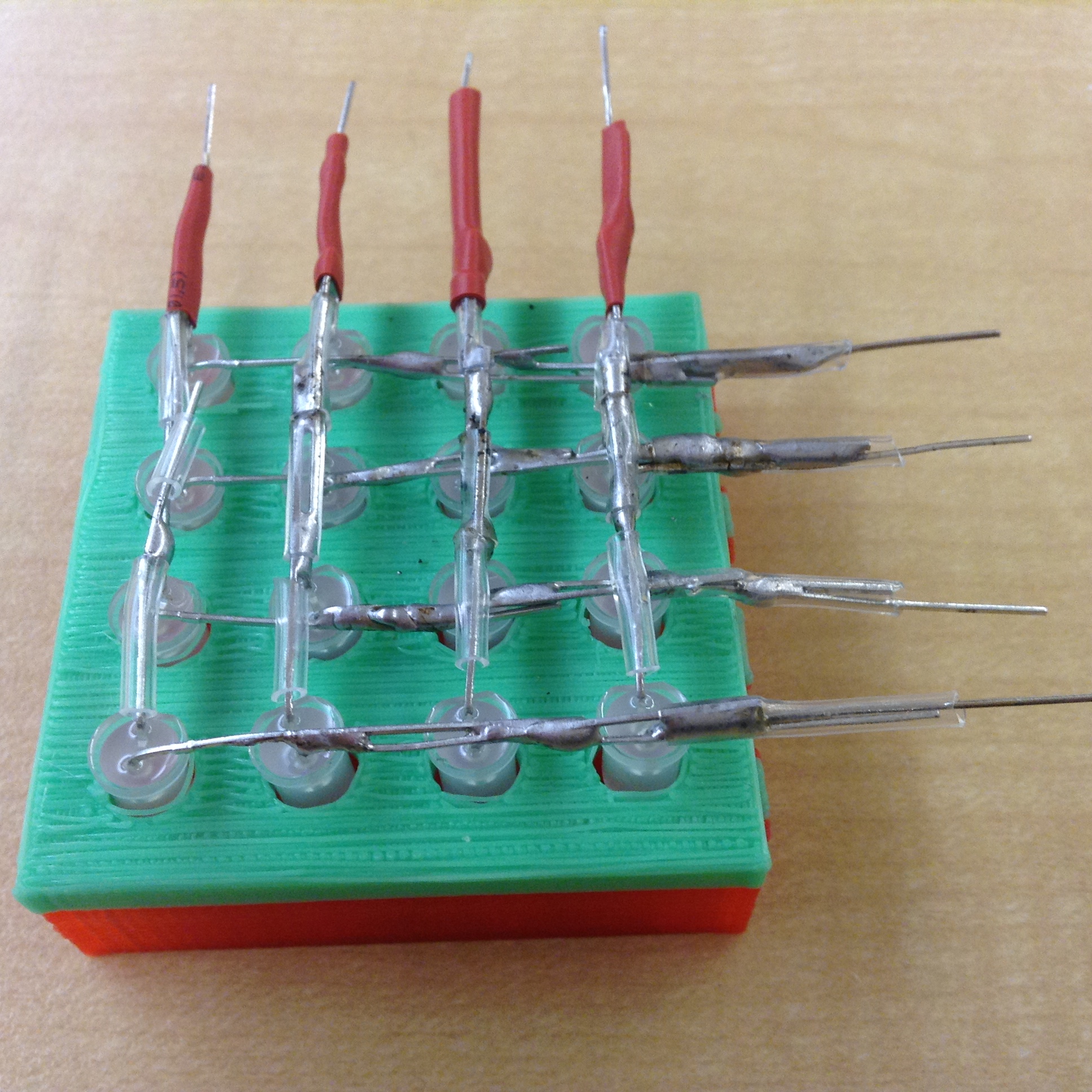 |
Take your time with this for better results. You may wish to review the numerous videos and tutorials available that describe how to construct and exercise 2D matrices and 3D cubes, both for the technique and the inspiration. For this task you will position the 16 Bicolor LEDs into the jig you have been provided in, oriented in such a way that, when bent, sets of four longer leads overlap (since these a bicolor LEDs I hesitate to refer to them as positive and negative). Solder each set of 4 together as in the photo, above right. AFTER SOLDERING EACH ONE use a bench power supply set to 2V to confirm the integrity of your connections. Make any adjustments to keep the leads AS STRAIGHT AS POSSIBLE.
Next, we do the same with the shorter leads, soldering in sets of 4, at right angles to their longer counterparts. Note. To avoid the possibility of electrical shorting, slide a short length of narrow heat shrink tubing over the potential problem areas. Click the photo above right to see an example of my use of clear tubing. Again, use 2V to test all 16 LEDs. I added a length of heat-shrink on the ends for additional support.
If you've made it this far you have 8 accessible leads, perfect for PORTA manipulation of the ATtiny84.
Task.
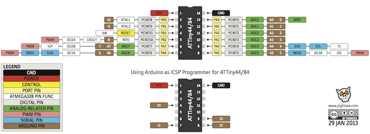
 You are aware that as few as three control lines are required to drive a sequence of shift registers. As such, you could use an ATtiny84, ATtiny85 or ATmega328P Arduino or standalone. If you are considering a tiny-based PCB project in the weeks ahead, you might consider using one for this project. The discussion that follows employs an ATtiny84 that has just enough pins to avoid the need for shift registers at all!
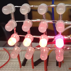
![]() Persistence of Vision Challenge 2. Quite apart from the refreshing level of engagement that I witnessed in class on Monday, one student even wondered why we hadn't been doing this intense work since September? Hmmm....
Persistence of Vision Challenge 2. Quite apart from the refreshing level of engagement that I witnessed in class on Monday, one student even wondered why we hadn't been doing this intense work since September? Hmmm....
|
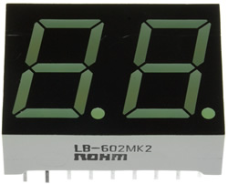
![]() POV: Dual 7-Segment Display Application. In class we developed and implemented a working solution for this task. Your challenge is to integrate this circuit into a meaningful application. Submit an ER summary of your application to handin by Saturday January 20 under with the Subject Line: POV: Dual 7-Segment Display Application.
POV: Dual 7-Segment Display Application. In class we developed and implemented a working solution for this task. Your challenge is to integrate this circuit into a meaningful application. Submit an ER summary of your application to handin by Saturday January 20 under with the Subject Line: POV: Dual 7-Segment Display Application.
 Reference: Exploring Arduino, pp. 41-59.
Tutorial: NYU: Serial Output from an Arduino to Processing
This project provides you with an opportunity to explore and showcase both your technical and creative skills. We have discussed the Model-View-Controller (MVC) design of project architecture. Your understanding of how to obtain and capture analog readings on the Arduino can produce the Model. Your experience in the use of the Processing language (Grade 10) to provide compelling visualizations will provide the View. All that remains is your ability to write great (efficient, documented, etc.) code to provide the Controller aspect of the MVC design to pull the project together.
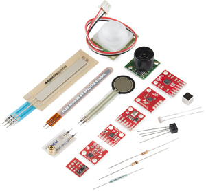
Sensors yielding varying analog voltage levels are available for monitoring almost any kind of natural phenomenon. Sparkfun offers a kit with a wide variety of them. Your toolkit comes with a few useful sensors that change resistance in response to external stimulation. The simplest one is the rotational actuation of the sweep arm of a potentiometer. P. Bagga used two of the these to manipulate the XY coordinates in his Grade 10 Etch-A-Sketch ISP. The LDR changes in response to incident light. Your TMP36 sensor yields varying voltage under changing temperature conditions. Your GP2Y0A41SK0F Sharp InfraRed distance measuring sensor is the most expensive sensor in your kit and could be used as a basis for a simple Theremin. Two of the more elaborate analog sensors from Sparkfun include the RGB Light Sensor and Triple Axis Gyro. The latter two are likely available at Creatron.
A few years ago, a Grade 11 ACE attached 6 temperature sensors to his Arduino, monitored the readings in round-robin style and placed streamed the data to the Serial port. Processing collected and recorded the data in a 6 by 100 matrix for his model, simultaneously presenting a view of the data below left. In 2015, R. Fletcher used the simulation of 5 TCRT5000L IR sensors below right to build his detection board to guide his Rover along a line.
| TMP36 Temperature Sensor View | TCRT5OOO IR Sensor View |
|---|---|
 |
 |
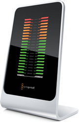
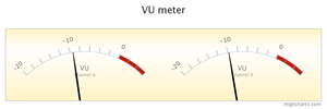 The two views above (line and bar) are two common ways to present the data. There are many others you have encountered either through your experience with Excel and/or various Presentation applications. The monitor on the first floor of See House presents a view of the solar data collected using dials, line charts and a thermometer for temperature. HighCharts.js offers web developers a package of JavaScript-based views. One of which is the VU Meter to the right. Ambitious ACES may wish to have an RGB Cube rotate in response to the motion of a Triple-Axis Gyro/Accelerometer.
Task.
 Using two or more sensors of your choosing (and any other components), imagine and develop an interesting MVC application that integrates Arduino with Processing to provide a compelling view of a sampling of real-world analog signals. Note: Arduino and Processing is a two-way street; each can communicate with each other :)
Do your research as soon as possible to allow time for the creativity to flood in.
SA, PB, NB, MB, JB, GC, TD, AE, OG, JG, NJ, MK, RK, KL, BL, MM, HM, RM, MP, ST
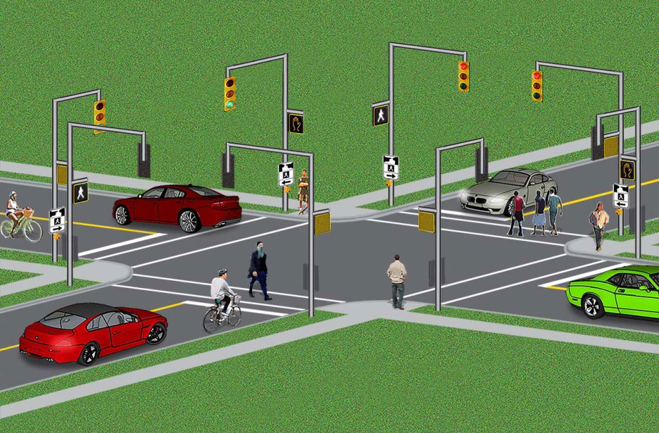
![]() Intersection Simulation. (Since many of you will be taking driving lessons in the near future it's a good time to review the workings of an intersection.) For your first 'common' project you are asked to develop a creative, Arduino based-simulation of an intersection that has, at the least, traffic lights in each of four directions. Your kit has red, yellow, and green LEDs. The simulation includes, of course, both software and hardware assets. Note. There are other features of a real-world intersection that you may wish to consider/investigate/simulate to enhance your Arduino knowledge and skills.
Intersection Simulation. (Since many of you will be taking driving lessons in the near future it's a good time to review the workings of an intersection.) For your first 'common' project you are asked to develop a creative, Arduino based-simulation of an intersection that has, at the least, traffic lights in each of four directions. Your kit has red, yellow, and green LEDs. The simulation includes, of course, both software and hardware assets. Note. There are other features of a real-world intersection that you may wish to consider/investigate/simulate to enhance your Arduino knowledge and skills.
Considerations
Engineering Report. Insert a page break at the end of your current ER, add TEI3M - Arduino centered on the page, and add a second page break before beginning your Intersection Simulation writeup for this project. Submit to handin by midnight, Sunday October 4. with the Subject Line: Intersection.
You will have 5 minutes to present your project to your peers on Tuesday October 6 and Thursday October 8.
![]() -
- ![]() Blink Variations. Modify the Blink sketch as required to accomplish each of the following progressively-challenging tasks. You are expected to write great code; the internet offers than enough bad code already; don't add to the supply.
Blink Variations. Modify the Blink sketch as required to accomplish each of the following progressively-challenging tasks. You are expected to write great code; the internet offers than enough bad code already; don't add to the supply.
Great code is beautiful and as much Art as it is Science.
It is
a tough, time-consuming and profoundly satisfying pursuit.
Do not be satisfied with code that simply works.
![]() Design Challenge 1 (ER). This report is a summary of your efforts to design a unique box (case and top) to house a circuit soldered to a perma-proto board from Adafruit using ViaCAD 2D/3D v10. Sections will include: Purpose, Reference, Acknowledgments, Procedure, Media and Conclusion. Mr. Paul Elia provided the instruction, with video and design support, Kreher Fiset-Algarvio and Darius Dadyburjor printed your cases and the acrylic tops were outsourced to Sawdust&Noise.
Design Challenge 1 (ER). This report is a summary of your efforts to design a unique box (case and top) to house a circuit soldered to a perma-proto board from Adafruit using ViaCAD 2D/3D v10. Sections will include: Purpose, Reference, Acknowledgments, Procedure, Media and Conclusion. Mr. Paul Elia provided the instruction, with video and design support, Kreher Fiset-Algarvio and Darius Dadyburjor printed your cases and the acrylic tops were outsourced to Sawdust&Noise.
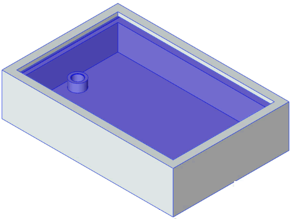
![]() Design Challenge 1. For your next challenge you are asked to design and produce a prototype of a case that ACES (and possibly the wider maker world) can use to house their perma-proto circuits. The best three cases will earn bonus credit on their designer's TEI3M final mark to be credited in June. Final judging of the cases will be undertaken by Grade 10 & 12 ACES, ACES' Alumni, along with Mr. Elia and myself. Thirty units of the winning case will be produced and sold in the Dragon's Lair, at cost. Also, I will send Adafruit a description of the project and, with any luck, they will feature your work as they did with our 50th Anniversary Clock Project from two years ago on their blog.
Design Challenge 1. For your next challenge you are asked to design and produce a prototype of a case that ACES (and possibly the wider maker world) can use to house their perma-proto circuits. The best three cases will earn bonus credit on their designer's TEI3M final mark to be credited in June. Final judging of the cases will be undertaken by Grade 10 & 12 ACES, ACES' Alumni, along with Mr. Elia and myself. Thirty units of the winning case will be produced and sold in the Dragon's Lair, at cost. Also, I will send Adafruit a description of the project and, with any luck, they will feature your work as they did with our 50th Anniversary Clock Project from two years ago on their blog.
While you are encouraged to dream, imagine, and create something unique, the ultimate case will be judged on a number of criteria as described below.
You are asked to develop TWO separate ViaCAD files,
You are to attach these two files to an email to handin by Saturday November 18.
![]() Digital and Analog: Reading and Writing. The presence of pedestrians or a longer-than-usual line of vehicles waiting to turn left are two situations that can influence the normal cyclic operation of a Traffic Light. at an intersection.
Digital and Analog: Reading and Writing. The presence of pedestrians or a longer-than-usual line of vehicles waiting to turn left are two situations that can influence the normal cyclic operation of a Traffic Light. at an intersection.
Task. In this followup to the previous project, you are afforded creative license to employ at least one example each of digital and analog, reading and writing, (four combinations) in a continuous simulation of your single Traffic Light. Since we've already employed appropriate digital and analog write statements, the latter being apply a PWM signal to dull the red LED, your challenge is to embed additional digital and analog read statements to make the simulation even more realistic and responsive.
The credit you receive for this submission will be based, in part, on your creativity and originality. For example, we used a potentiometer in class on Thursday, acting as a simple voltage divider, to demonstrate the use of the analogRead() statement. On the other hand, a variety of sensors exist (that are more intersection-appropriate) that either produce varying voltages themselves or can be used in conjunction with other resistive components to divide voltage. If you get an early jump on this two-week assignment you can easily secure these devices!
Include the standard Reference, Procedure, Code, Media and Conclusion subsections. Finally, your video should clearly explain your use of the four requirements (digital and analog; reading and writing).
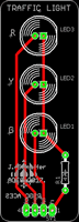
![]() Traffic Light Assembly and Testing. After inserting a divider page in your ER indicating the start of this course, TEI3M, begin this year's submissions with a report entitled, Traffic Light Assembly and Testing. The focus of this first summary is the soldering of the device and simple testing. For the assembly aspect of this project you will document your soldering of the device through media acquisition that you can include in your report. For the testing aspect, you will include media as well as a simple sketch based on the Blink sketch that we will explain in class on Tuesday and Thursday.
Traffic Light Assembly and Testing. After inserting a divider page in your ER indicating the start of this course, TEI3M, begin this year's submissions with a report entitled, Traffic Light Assembly and Testing. The focus of this first summary is the soldering of the device and simple testing. For the assembly aspect of this project you will document your soldering of the device through media acquisition that you can include in your report. For the testing aspect, you will include media as well as a simple sketch based on the Blink sketch that we will explain in class on Tuesday and Thursday.
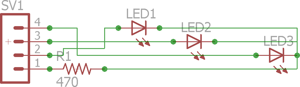
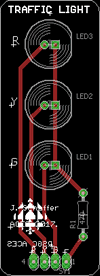
In your report, include the sections Purpose, Reference, Procedure, Code, Media, and Conclusion in Heading 2 style. A full Parts Table should appear right-aligned within the Procedure section. The schematic and board graphics of Jasper's PCB appear below and should be edited as you see fit and strategically embedded within your report.
| Schematic | Board Layout |
|---|---|
 |
 |