| 2014-2015 TEI3M Engineering Tasks |
![]()
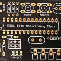
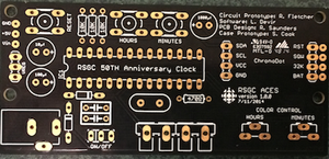
![]() Part 2. For Part 2 of this project, we're going to design a custom circuit board to replace the general purpose prototype board of Part 1 and outsource its fabrication.
Part 2. For Part 2 of this project, we're going to design a custom circuit board to replace the general purpose prototype board of Part 1 and outsource its fabrication.
Robert Saunders will consult with you in the development of a common board with a view to having a combination of both through hole, and surface mount components.
| Role | Details | ACE |
|---|---|---|
Media, Communications (Mr. Christie's team) |
Web, Photos, Video |
Ross, Jamie |
Production |
Assembly, Soldering, Code, Inventory |
Jackson, Justin, Ryan |
Business (Mr. Kotecha's team) |
Design, Packaging, Pricing, Marketing |
Adam, John |
Writing |
Web Copy, Tutorial |
Ryan, John |
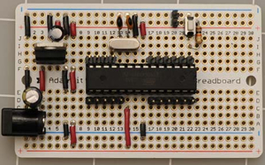
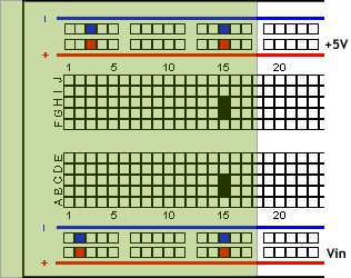
![]() I2C Data Wall, Part 1. The goal of this project is to create an I2C bus-based data wall that includes time, date, and temperature features displayed on a 7-segment display bank, mounted on a perma-proto 1/2 size breadboard and housed in a simple enclosure. The photo to the right, taken from the internet, gives you a rough idea of how you might begin to assemble an embedded ATmega328P-based platform as a foundation for your I2C components.
I2C Data Wall, Part 1. The goal of this project is to create an I2C bus-based data wall that includes time, date, and temperature features displayed on a 7-segment display bank, mounted on a perma-proto 1/2 size breadboard and housed in a simple enclosure. The photo to the right, taken from the internet, gives you a rough idea of how you might begin to assemble an embedded ATmega328P-based platform as a foundation for your I2C components.
Task.
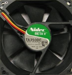
Part 1. Reading RPM. Confirm Manufacturer's Claim to the Serial Monitor.
Part 2. LCD Display. Provide meaningful reporting.
Part 3. Switching On/Off. Demonstrate 5V/12V switching using an IRF520 N-Channel MOSFET
Part 4. Temperature Monitoring. Using either the LM35DZ or TMP36 temperature sensor devise a temperature range that is easy to demonstrate (efficient) switching of the fan on and off under control of your off-board setup.
You are encouraged and capable of designing the structure of the experiments and the contents and presentation of your ER submission. Don't underplay this opportunity. Plan and take calculated risk.
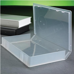
I have a bold academic vision for RSGC based on a circular instruction model in which senior students provide both products and services to junior students. We're going to field test this model, this year, in our area of electronics. The physical product is a compact breadboard-based kit with any number of swappable boards to enable efficient prototyping of circuits. The services include mentoring, tutoring, teaching, curriculum development, partnerships, marketing, and promotion to name a few.
Electronics projects and components require a variety of voltage and amperage conditions. An adapter board that fits securely onto a breadboard and delivers both the raw voltage on one rail, user-adjustable power on another rail, with common ground rails, would be a instructive component for efficient prototyping for both the beginner and the more experienced developer. Task.
|
Task.
|
Task.
|
![]() Surprise Me 1. We have spent the first two months exploring the capabilities of the Arduino and a dozen or so interfacing components from the ARD-100 manual. For your first ER submission of the year, you are asked to imagine, design, and implement an Arduino-based project that you find inspiring. The best projects will combine an elevated degree of risk, components from your kit, one or more additional components that you have sourced, and additional web research. Furthermore, the best projects will leave viewers wondering how you ever even came up with the idea for such a project.
Surprise Me 1. We have spent the first two months exploring the capabilities of the Arduino and a dozen or so interfacing components from the ARD-100 manual. For your first ER submission of the year, you are asked to imagine, design, and implement an Arduino-based project that you find inspiring. The best projects will combine an elevated degree of risk, components from your kit, one or more additional components that you have sourced, and additional web research. Furthermore, the best projects will leave viewers wondering how you ever even came up with the idea for such a project.
| ACE | New | Image Link | Description | Reference | Risk Factor (out of 10) |
|---|---|---|---|---|---|
| AD | LCD | 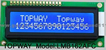 |
Temperature data presented on an LCD Screen The objective of our primary “Your Choice Project” was to create an un-curated assignment. Up until now in the 11th grade, all of our learning has been very closely monitored and set by a curriculum or by our teachers. This is the first real opportunity we have to choose our own learning path and follow through with it until we see fit that works to our expectations. The project I have chosen was to display environmental temperature readings upon a LCD display. It takes the analog reading from the temperature sensor and after converting it to Celsius, pushes it to LCD. We were challenged to use a part that we have never used or seen before. For my project that was the LCD display with an LED backlight. Having never seen / used the part before, the difficulty level is increased. The overall objective of the project is for the student to take control of his own learning and curate his own enthusiasm and passion. |
5 | |
| JD | Four 7-Seg | 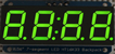 |
Kitchen Timer My first project in TEI3M will be a Digital Kitchen Timer. I have a 7 segment led display matrix arranged with a premade backpack which converts the data on the input pin into numbers. These numbers will be set by a potentiometer using the analogRead function of the arduino. Once set, the numbers will count down to zero and then trigger some kind of audio cue to let the user know that their time is up. Parts included in the project are wires, resistors, the 7 segment displays and their backpack, a potentiometer, my arduino, and a piezo disc. What I hope to accomplish with this assignment is attaining a better knowledge of analog inputs and work towards building a Data Wall to use as my ISP. |
5 | |
| RH | RTC1307 |  |
Clock Resubmission: November 4 |
5 | |
| JL | (Prox/US) Sens. |  |
Theremin |
3-? | |
| RP | MSGEQ7 | Equalizer Part 1. Processing Visualization |
6.5 | ||
| JR | MUX |  |
Universal Sensor Shield (USS) Russett Right now I'm working on creating a 4-bit computer. For this computer design I need to understand how each individual part works. One of these parts is a multiplexor. A multiplexor is like a siphon in the sense that it takes multiple lines or buses of data and directs them to a smaller bus than before. For example, a certain type of multiplexor can take two 4-bit lines and direct one or the other onto single 4-bit output bus. The multiplexor for this project will take 16 different analog inputs and direct them, one at a time, to a single input pin on an arduino. This project will have many applications, like the 4-bit computer, and it can be applied to any project with more than the standard number of sensors on an arduino uno board. One such project may be the ACES Datawall. |
6 | |
| JY | Microphone | Audio Capture. Processing Visualization An overview of the task that I will be undertaking would be researching and implementing the Electret Microphone Ampleifier-Max9814 with a Processing visualization. The first step will be researching the aforementioned part by finding and reading Datasheets and using Adafruitís, the supplier, information and libraries. The second step will be creating the code in Arduino to read the information, sound levels from the room, given from the part. The final step will be creating the code in Processing to interpret the information given from the Arduino and displaying that information visually with a bar, which display the current audio level, and a graph, which will display the recorded audio levels from the past ~100 seconds. |
5 |
Projects