 The Tune Player. The Tone Player circuit is a pretty cool but, as you rightly said, it leaves plenty of room for better engineering. Your task this week is to implement changes to the software and hardware to improve the quality of the output, specifically to reproduce the Jeopardy Theme song, "Think!", as faithfully as possible (I just happened to find this highly-appropriate JeopardyWii screenshot). You should start by reviewing the state of the current code and the limitations of a 4-bit DAC...
- What is the justification for calling the digitized sine wave array sin16[] and populating it with 32 values?
- Download the Excel file MusicalNotes.xlsx and develop your own values for a 4-bit digitized sine wave on the Worksheet entitled Digitized Sine Wave.
- Review this primer on the mathematics of musical notes: Physics of Music - Notes. On the Worksheet entitled Note Characteristics, complete the data for the notes in Octave 4 and 5 so that the waveforms of A4, C4, and A5 appear on the chart.
- What would be the implications of upgrading to an 8-bit DAC? (Hint: An upgrade would bound to impress any teacher in his right mind...)
Task.
- Determine an encoding strategy of mono melodies in general (and the Jeopardy Theme specifically) that offers you maximum flexibility to reproduce the audio within the system we have available.
- Encode your specially chosen song using the strategy developed in Step 1.
- Engineer a reproduction as faithfully as possible.
- Provide an ER Summary by the deadline under the title, Tune Player, and submit by the deadline.
![]() Thermal Management Part 9. Stand Alone Solar Fan System.
Here are a few of the design decisions for this configuration,
Thermal Management Part 9. Stand Alone Solar Fan System.
Here are a few of the design decisions for this configuration,
- modular and portable
- low physical and carbon footprint
- student takeaway
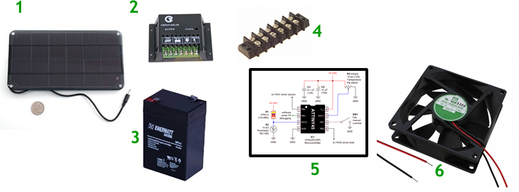
Major Parts List
| # | Component |
Specifications |
Price (approx) |
Source/Supplier |
|---|---|---|---|---|
1 |
Solar Panel |
6V, 0.5A, 3.4W |
$30 |
|
2 |
Charge Controller |
6V, 500 mA |
$15 |
|
3 |
SLA Battery |
6V, 5A |
$30 |
|
| 4 | Terminal Block | 8 posts - 16 Wire | $10 | Digikey |
5 |
Fan Control Circuit |
5VReg, ATtiny85, LM35DZ, MOSFET |
$10 |
|
6 |
DC Fan |
5V, 0.28A |
$10 |
- DOCUMENT YOUR ACTIVITY FOR YOUR ER
- Installation!
- DOCUMENT YOUR ACTIVITY FOR YOUR ER
 Friday April 13.
- DOCUMENT YOUR ACTIVITY FOR YOUR ER
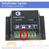
- Interface your 5V Regulator Board (from last term) with the Terminal Block to provide constant power to your ATtiny85-based control circuit.
- Draw power directly from the Battery terminals, not the Load terminals. (Unless we figure out how to invert it's behaviour)
-
 Under this setup, confirm your LED turns on when you pinch the LM35.
- DOCUMENT YOUR ACTIVITY FOR YOUR ER
- Complete cable preparation
- Discussion of how the Charge Controller drives the Load Terminals
- ATtiny85 Fan Controller circuit: http://www.embedds.com/thermistor-regulated-dual-fan-controller/
- DOCUMENT YOUR ACTIVITY FOR YOUR ER
- Prototype Development (with the exception of your Fan Control Circuit)
- Using your 18/2 wire (+Red/-White) together with various connectors (ring, spade), fabricate cables and assemble the system using Components 1,2,3,4 and 6.
- Take your system outside and confirm its functionality.
- Overview of Standalone Solar Fan System Components
![]() Thermal Management Part 8. ATtiny85 Port.
Thermal Management Part 8. ATtiny85 Port.
We continue to set our sights on EARTH WEEK (April 16-20), in particular, Thursday April 19.
On this day we'll install our solar-powered fan systems in the RSGC Greenhouse
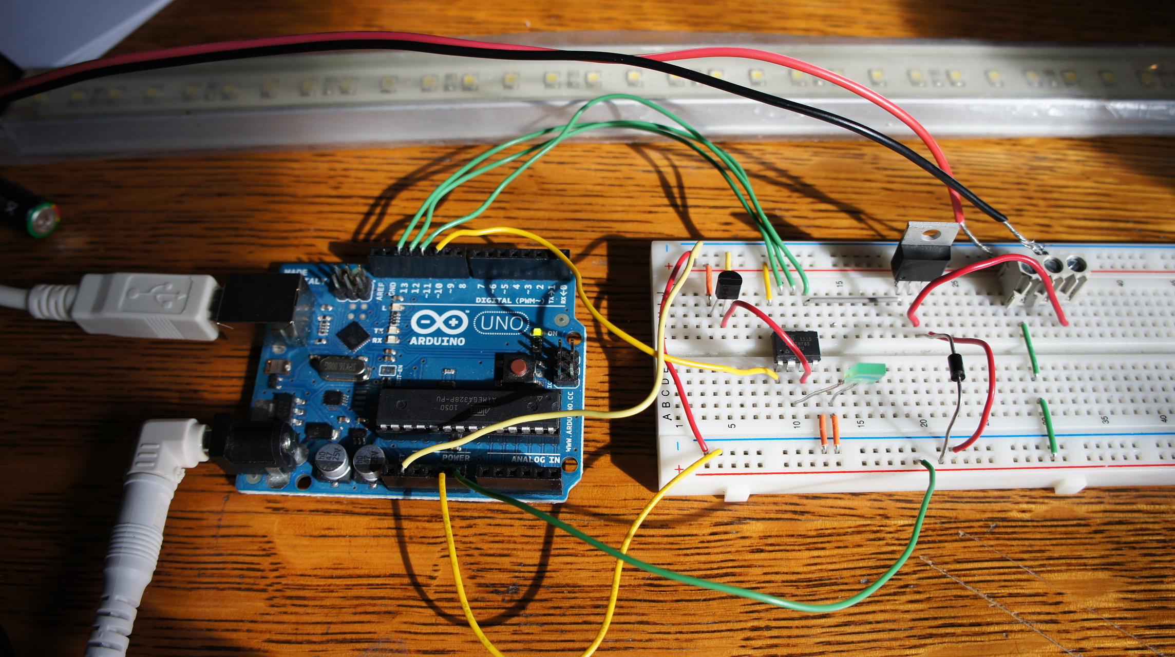
The objective of Stage 8 is to shrinkify your Thermal Management System in order to minimize both the physical and power footprint of the device for the RSGC Greenhouse. As I didn't have a 12V DC fan at home with me this weekend, I substituted a 12V Light Bar I had acquired for a project a few years ago. As the photo reveals, the ATTiny85 receives temperature data in the form of an AD conversion on ADC2 (Pin 3) from the LM35. Pinching the sensor gradually raises the temperature to the turn-on threshold (23°C in this example) at which point a status LED on Pin 2 signals the start of a PWM period on PWM0 (Pin 5).This signal is supplied to the Gate pin of the RFP30N06 which connects the Drain to its Source, grounding the Light Bar. It turns on. Removing heat allows the temperature to fall to a point that turns the LED and PWM signal off.
You asked asked to duplicate this circuit replacing the Light Bar with your fan. Submit your summary on Sunday March 11.
Here's a video demonstration of the circuit. Click on the photo below for an enlargement.
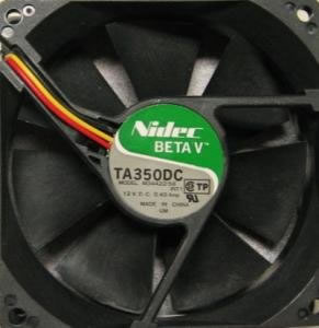
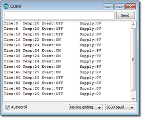
![]() Thermal Management Part 7. Fan Speed. The datasheet for your fan (Nidec Model #M33422-33) quotes a fan speed of 3100 RPM. In this stage of our project we are going to confirm this claim by counting the rotations and displaying these results on the Serial Monitor.
Thermal Management Part 7. Fan Speed. The datasheet for your fan (Nidec Model #M33422-33) quotes a fan speed of 3100 RPM. In this stage of our project we are going to confirm this claim by counting the rotations and displaying these results on the Serial Monitor.
From the diagram to the right, you can see that the Signal wire (yellow) spans a pull up resistor and the collector of internal transistor. The base pin of the transistor is attached to a Hall effect sensor. The result is that the signal wire completes TWO full cycles for each rotation of the fan. For our purposes, we'll have to account for this (divide by 2) in our calculations of fan speed.
Task 1. Tuesday February 14
- Review the tutorial Reading Fan RPM and examine the code.
- Using your 12V Regulator and Arduino, assemble the circuit as described with a pull up resistor with LED to monitor the rotation.
- Create the sketch FanSpeed and add the author's code. Run the circuit and confirm both the LED and Serial Monitoring.
 Task 2. Thursday February 16
- Review the tutorial Reading Fan RPM and examine the code.
- Using your 12V Regulator and Arduino, assemble the circuit as described with a pull-up resistor with LED to monitor the rotation.
- Create the sketch FanSpeed and add the author's code. Run the circuit and confirm both the LED and Serial Monitoring.
- Now to put it all together. View the short video that shows all the pieces working together.
- Create the sketch FullFanControl that senses the temperature, drives the fan accordingly, captures the fan speed and summarizes the results on the Serial Monitor.

![]() Thermal Management Part 6. Air Flow Management. With your 5V/V+ Voltage Regulator Board completed you can now tackle the next instalment of the Thermal Management Project.
Thermal Management Part 6. Air Flow Management. With your 5V/V+ Voltage Regulator Board completed you can now tackle the next instalment of the Thermal Management Project.
Air within a greenhouse should remain bouyant for healthy plant growth. Fans can be employed continuously to provide for the circulation of the outside air through its interior. Furthermore, as the interior temperature changes, fan speed can be adjusted to provide optimal flow.
Task (Monday February 6)
- Read pp. 70-71 in your Gettting Started with Arduino handbook
- From the labelling on the case of the DC Fan and this datasheet determine its power requirements.
- With the help of your Voltage Regulator and your Arduino prototype this circuit on your breadboard.
- Create the Arduino sketch FanOnOff, that turns of the fan on and off at 10s intervals.
Task (Wednesday February 8)
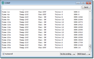
 To keep the air moving at an appropriate rate in the greenhouse, it is necessary to supply voltage to the fan in proportion with the temperature. Interval reporting (5s?) of voltage and temperature readings to the Serial Monitor is required for confirmation.
- First, connect your fan to the Variable Power Unit at your station. By gradually increasing the voltage up to a maximum of 12V, observe how the fan behaves over this range. With a better understanding of the behaviour of the fan we can develop some code.
- Create the Arduino Project FanControl, and develop a sketch that will use an LM35DZ attached to A0 for input and your DC Fan connected to Pin 9 as one of the two outputs. The other output is your Serial Monitor that will log the activity of your system in the manner depicted to the right.
- Your sketch will map the celsius reading over the interval [fanOFFTemp,fanONTemp] to the legal pwm range [0,255]. The pwm value can further map to the voltage range [0,12] (the upper bound is the upper bound of your V+ supply).
Add a new Subsection 6 to your Thermal Management Project entitled Air Flow Management. Develop a comprehensive summary of this Activity.
 5V/12V Breadboard-Compatible Regulator. It's an appropriate time to put your rapidly-developing EAGLE skills to important use on a project of our own design and implementation.
Many Arduino projects (including the next the stage of our Thermal Management Project) involves using the 5V Arduino platform to drive higher loads, typically of the 12V variety like a cooling fan. To facilitate efficient prototyping an adapter board that would fit onto the end of a breadboard and deliver 5V along one power rail and 12V along the other, with common ground rails, seems like a pretty useful component.
Task.
- Sparkfun offers something similar to what I have in mind. Review all the images the page offers to fully understand what their design provides. Kindly, Sparkfun offers the EAGLE files for most of it's boards enabling an even closer look at the designs.
- Sketch out a design on a piece of paper. In addition to delivering the input and output supply points and connector types, consider switches, momentary PBs, led indicators, thermal protection, stability points, etc.
- Assemble a working prototype of the board to confirm your design.
- Using EAGLE, create the schematic.
- Convert your schematic to a board and measure the size of the breadboard to assist with determining the size of the adapter board.
- Place the parts and complete the traces.
- Make the board.
- Connect to breadboard and confirm 12V in one rail and 5V in the other.
- Take lots of photos and embed them with your text into a comprehensive writeup.
Printed Circuit Boards.
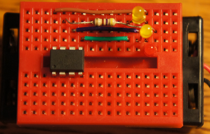
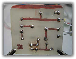 PCB 1: Sharpie. The PCB to the right resulted from I. Comery (RSGC '10) using a Sharpie pen to draw the Automatic Night Light circuit on a piece of copper clad board and then etching the design in a tank filled with Ferric Chloride. For your first foray into the area of Do-It-Yourself Printed Circuit Boards (DIY PCBs) consider the simple Resistor/LED circuit below,
Tasks. (document the steps below with photos as you go)
- Using pencil and paper draw the circuit as close as you can to one you might expect from a preprinted PCB. Think about
,
- the outer dimensions of the board
- the width of the traces
- the sizes of the pads you'll be soldering component leads to
- the spacing between pads, etc.
- Prepare a piece of copper clad board (CCB) as per the instructions given in class, drill a hole in one corner and attach a 0.5 m piece of string to the board
- Using your sharpie, draw your circuit from 1 onto the CCB and drop it into the etchant tank.
- Clean your etched board as per the instructions and drill the holes for the components.
- Solder the components and test your board.
- Prepare an ER submission entitled Printed Circuit Boards with subheading PCB 1: Sharpie.
 Thermal Management. November's focus will be an introduction to thermal detection and management. There can be little doubt that with climate change issues very much in the forefront, managing heat will be an important concern for engineers of the future.
This multi-part project will combine the following concepts,
Thermal Management. November's focus will be an introduction to thermal detection and management. There can be little doubt that with climate change issues very much in the forefront, managing heat will be an important concern for engineers of the future.
This multi-part project will combine the following concepts,
- Analog-to-Digital Conversion
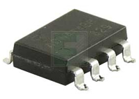
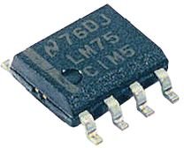
- Temperature Sensing devices: NTC/PTC Thermistor, LM35 (TO-92) & LM75CIM5 (SOIC-8)
- Driving Higher Power Loads
- Arduino's math.h library
- Reporting: Text and Graphics (Processing)
- Soldering SOIC components
- Data Logging
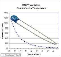
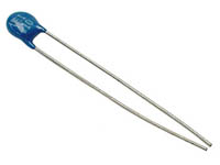
![]() Part 1. NTC Thermistor. The goal of Part 1 of this
interfacing project is to incorporate the use of an NTC
Thermistor to detect temperature. Electronics in Schools offers an excellent starting point.
Part 1. NTC Thermistor. The goal of Part 1 of this
interfacing project is to incorporate the use of an NTC
Thermistor to detect temperature. Electronics in Schools offers an excellent starting point.
Task. Once the principle is conceptually understood, undertake the follow steps,
- Configure a voltage divider with the NTC Thermistor (R1) in series with a 10K variable resistor, VR1. Initially, set the variable resistor to it's maximum (10K Ω).
- Configure the Arduino's Analog Pin 0 for input to read the voltage between the two resistors.
- Implement a simple sketch to read the raw ADC value and display it continuously to the Serial Monitor.
- Pinch and hold the head of the thermistor and observe the changes in the raw ADC values. Remove your hand from the thermistor and, again, observe the sequence. Formulate an explanation for this behaviour.
- To determine how this raw value can be converted to a meaningful temperature reading we need to do a little research. We can start with Wikipedia. Notice under
the Section entitled B constant equation, the formula for R(T),
The component you have been provided with has the following characteristics: B constant:4100; R0:10KΩ @ T0=25°C. Here's my attempt at deriving Temperature as a function of the raw ADC result on Channel 0. I have prepared this Excel worksheet presenting the graph of R(T) for this component. For fun, select a raw value from the stream appearing on your Serial Monitor and see if you can calculate the corresponding ambient temperature using the formula presetned at the bottom of my derivation.
- Read this author's discussion and coding example under the Section entitled The Simple Code. Notice the inclusion of the math.h library that offers sketches access to additional math functions beyond those offered in the basic Arduino language.
- Copy & paste the the author's sketch, verbatim, to determine whether it runs on your prototype.
- To determine if you can code complex mathematical formulas, comment out the body of the double thermistor(int rawADC) function and recode it as defined by the last formula on my derivation page. Be sure to adapt the result from Kelvin to Celsius.
- Be sure to display the temperature to the Serial Monitor.
- Calibration. The temperature readings you are gettings may seem a little warmer than you might suspect. Grab a DMM and notice that it has a TEMP setting on the dial. Adjust the variable resistor in your circuit until the results on your Serial Monitor match those reported by the DMM.
 Develop an ER entry under the title of Project 5. Thermal Management. Under a subheading in Heading 2 style include Part 1. NTC Thermistor and include the usual sections (Reference, Purpose, Parts List, Sketch, Media).
Within the Media section add your own Fritzing version of the breadboard similar to the one to the right (minus the Sample text). Submit by the deadline.
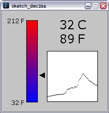
![]() Part 2. Serial Communications Using Processing. From the outset, your laptop and Arduino have been sharing data. You've uploaded your sketches to the Arduino and the Serial Monitor has echoed the data stream returned by the Arduino. The goal of this segment of our Thermal Project is how raw serial data (non-ASCII) transmitted by the Arduino can be read and displayed graphically on your laptop. The Processing language is ideally suited for this purpose.
Part 2. Serial Communications Using Processing. From the outset, your laptop and Arduino have been sharing data. You've uploaded your sketches to the Arduino and the Serial Monitor has echoed the data stream returned by the Arduino. The goal of this segment of our Thermal Project is how raw serial data (non-ASCII) transmitted by the Arduino can be read and displayed graphically on your laptop. The Processing language is ideally suited for this purpose.
Task.
- Review this excellent introduction to Serial Out using an Arduino from ITP Physical Computing.
- Now, review this description of an project similar to ours (it uses an LM35 - our next project!) that uses the techniques explained in Step 1.
- Software. Note the blog presents two sketches: one Arduino and one Processing. Satisfy yourself that you understand the purpose of each. Create and upload the sketches, solving the debugging issues as you go.
- Confirm the Processing sketch generates output similar to graphic to the right.
Under the subheading (Heading 2 style) include Part 2. Serial Communications Using Processing with the sections: Purpose, Reference, Parts List, Procedure (explain the purpose of each if the two sketches and Fritzing image), Sketch, and Media (photo and include a screen capture of the graphic output of your Processing sketch).
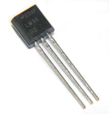
![]() Part 3. Precision Centigrade Sensor (LM35DZ). The LM35DZ datasheet begins with, "The LM35 series are precision integrated-circuit temperature
sensors, whose output voltage is linearly proportional to the
Celsius (Centigrade) temperature..."
Part 3. Precision Centigrade Sensor (LM35DZ). The LM35DZ datasheet begins with, "The LM35 series are precision integrated-circuit temperature
sensors, whose output voltage is linearly proportional to the
Celsius (Centigrade) temperature..."
Task.
- Again, Electronics in Schools offers a terrific overview of the LM35DZ.
- Develop a circuit prototype similar to the circuit presented in the blog.
- Create and upload the sketches, solving the debugging issues as you go.
- Confirm the Processing sketch generates output similar to Part 2.
- Modify the Processing code by removing the thermometer and enhancing the 2D animated plot. The plot should be enlarged, axes should be calibrated and labelled, either point or line grid added and the data point coloured in red.
Under the subheading (Heading 2 style) include Part 3. Precision Centigrade Sensor (LM35DZ) with the usual sections (Reference, Purpose, Parts List, Procedure, Code, and Media).
![]() Part 4. Multiple Sensors: Polling. The Arduino UNO has 6 analog input pins (A0-A5), each of which will monitor its own LM35DZ sensor. I've prepared an animation to the right that demonstrates the output of the sensors (I pinched each one in succession).
Part 4. Multiple Sensors: Polling. The Arduino UNO has 6 analog input pins (A0-A5), each of which will monitor its own LM35DZ sensor. I've prepared an animation to the right that demonstrates the output of the sensors (I pinched each one in succession).

Task.
- Using your triple-size breadboard, distribute your 6 sensors in a large matrix pattern, providing each with access to V+ and Gnd, and connecting their Vout pins to the 6 Analog In pins on the Arduino.
- Modify your Arduino sketch from Part 3 to read and stream the outputs from A0 through A5 in round-robin style.
- Modify your Processing sketch from Part 3 to accommodate the data streaming from the six sensors, reading each input in round-robin style (Sensor 0 through Sensor 5). Your Processing Code must be designed to be scalable and efficient. Scalability is achieved by defining as many variables at the top of your code as you can think of and creating dependency on these variables throughout your sketch. Efficiency is achieved by placing as much of the one-time code in the setup() method, and only the code that needs to be executed with each iteration in the draw() method.
- After every sixth reading of the input stream (Sensor 5), your code should calculate and update the display of the average temperature of all 6 sensors.
- Using Processing's saveFrame("filename-####".ext) command, record screen captures (100-200). Using an app capable of doing so, assemble the images into an Animated Gif, upload them to your Web Publishing folder and provide a link to it from one of the images inserted into your ER.
Under the subheading (Heading 2 style) include Part 4. Multiple LM35DZ Sensors with the usual sections (Reference, Purpose, Parts List, Procedure, Code, and Media).
![]() Part 5. Multiple Sensors: Multiplexing. A one-to-one relationship between the Arduino's I/O pins and interfacing components is not always possible. Whether you're reading analog data from an array of 64 sensors or you're writing to an LED cube with 512 LEDs (8×8×8), doing more with less is no less applicable in electronics.
Part 5. Multiple Sensors: Multiplexing. A one-to-one relationship between the Arduino's I/O pins and interfacing components is not always possible. Whether you're reading analog data from an array of 64 sensors or you're writing to an LED cube with 512 LEDs (8×8×8), doing more with less is no less applicable in electronics.
To overcome the limitation of six Analog In pins available on the Uno, we can exploit a strategy known as multiplexing. In this segment you will increase your sensing matrix to nine LM35DZs arranged in a large 3×3 grid, and attach them all to Analog In pin A0!
Task.
 Review this tutorial on how a microprocessor multiplexing strategy can monitor an array of light sensors.
- Review this tutorial on employing the CD4067B Multiplexer to light 16 LEDs in sequence.
- under development...
![]() LM75. Hysteresis.
LM75. Hysteresis.
![]() LED Dice. The female receptacles that were required in the previous project offered two advantages: they reduced the chances that overheating from soldering would damage the LEDs in the display and it made it easier to adapt the project for another purpose.
LED Dice. The female receptacles that were required in the previous project offered two advantages: they reduced the chances that overheating from soldering would damage the LEDs in the display and it made it easier to adapt the project for another purpose.
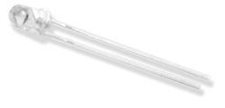
For this modification of Project you are going to use 3mm High Brightness White LEDs used in fibre optic applications in place of the 16-segment Alphanumeric Display.
Task.
- Replace the 16-segment Alphanumeric Display with the six 3mm High Brightness White LEDs you have been provided with. Place the anode leg of each LED in one header bank and the cathode leg in the opposite bank.
- Add a tact switch as required by the schematic on page 56.
- Enter the sketch found on pp. 57-58 of our workbook, adapting it for this implementation.
- To be continued...
 Monthly Project. Each of your monthly projects will be documented in your ER.
Task.
- Add a new to your ER entitled Appendix C. Monthly Projects in Heading 1 Style.
- Add an new subheading on the same page, entitled October 2011, in Heading 3 Style. Writeups for subsequent months will start on a new page, each time.
- Develop your own structured writeup with text, graphics, photos and links
- Update your Table of Contents and submit to handin by the posted deadlines.
Objectives. I developed this project to introduce you to six new concepts. These include,
- Working with a segmented display device
- Mapping complex pin assignments
- Working with Arduino libraries
- Brief exposure to the C/C++ language
- Adapting (and correcting!) existing code to fit slightly different specifications
- Development of an Arduino Shield of your own design
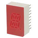
Part A. The 16-Segment Alphanumeric Display. Seven-segment LED displays are designed to represent a single decimal digit (0-9). To display alphabetic characters the 16-Segment display was developed. You will familiarize yourself with this device in Part A.
Task A.
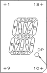
- You have been provided with a 16-segment (17 segments if you include the decimal point). Examine the labelling on the side of the device and, use your internet search skills, scrounge up an appropriate datasheet. (You might want to obtain a hard copy and hang onto to it tightly.)
- From the datasheet, identify the necessary electrical characteristics of the package before probing the pins by number to determine the respective segments they map to. Create a Word table that summarizes the pin-to-segment mapping.
- Edit your ER under the entry indicated above, with sections that include, Purpose, Reference, Pin/Segment Map and Media.
| 16-Segment Alphanumeric Display | Pin Segment Map |
|---|---|
 |
 |
 Part B. Code (PDE and C/C++ Library). In this stage, you will gain some exposure to the C/C++ programming language and the concept of an Arduino library.
Task B.
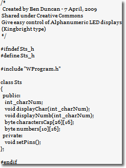
- Go to this Alphanumeric LED Display Library site and familiarize yourself with the author's offering as best you can.
- Using the code at this site, create the Sts.h, Sts.cpp and BasicUseLoop.pde files on your laptop. Place them in your TEI3M folder for now.
- Examine the code carefully, identifying any obvious syntax errors. (Note: Either because this technology is so new, or because it is so accessible to people with little or no prior knowledge of software, you should be prepared for an unusually high number of errors in code that is posted online)
- The code the author developed was for a slighlty different device that yours. Examine the parts his discussion and code that defines both the pin/segment mapping and digital voltage levels and draw any necessary observations and/or implications for your project.
- Read this short tutorial on how to create, and where to place, an Arduino library.
- Undertake the steps necessary to create the Sts library that will be available for future sketchs.
- Create the Arduino sketch, BasicUseLoop, and add the sketch by the same name.
- Compile (Verify) the sketch as often as necessary to eliminate all errors.
- Add the commented code files (Sts.h, Sts.cpp and BasicUseLoop.pde) to the Code section of your ER writeup and submit.
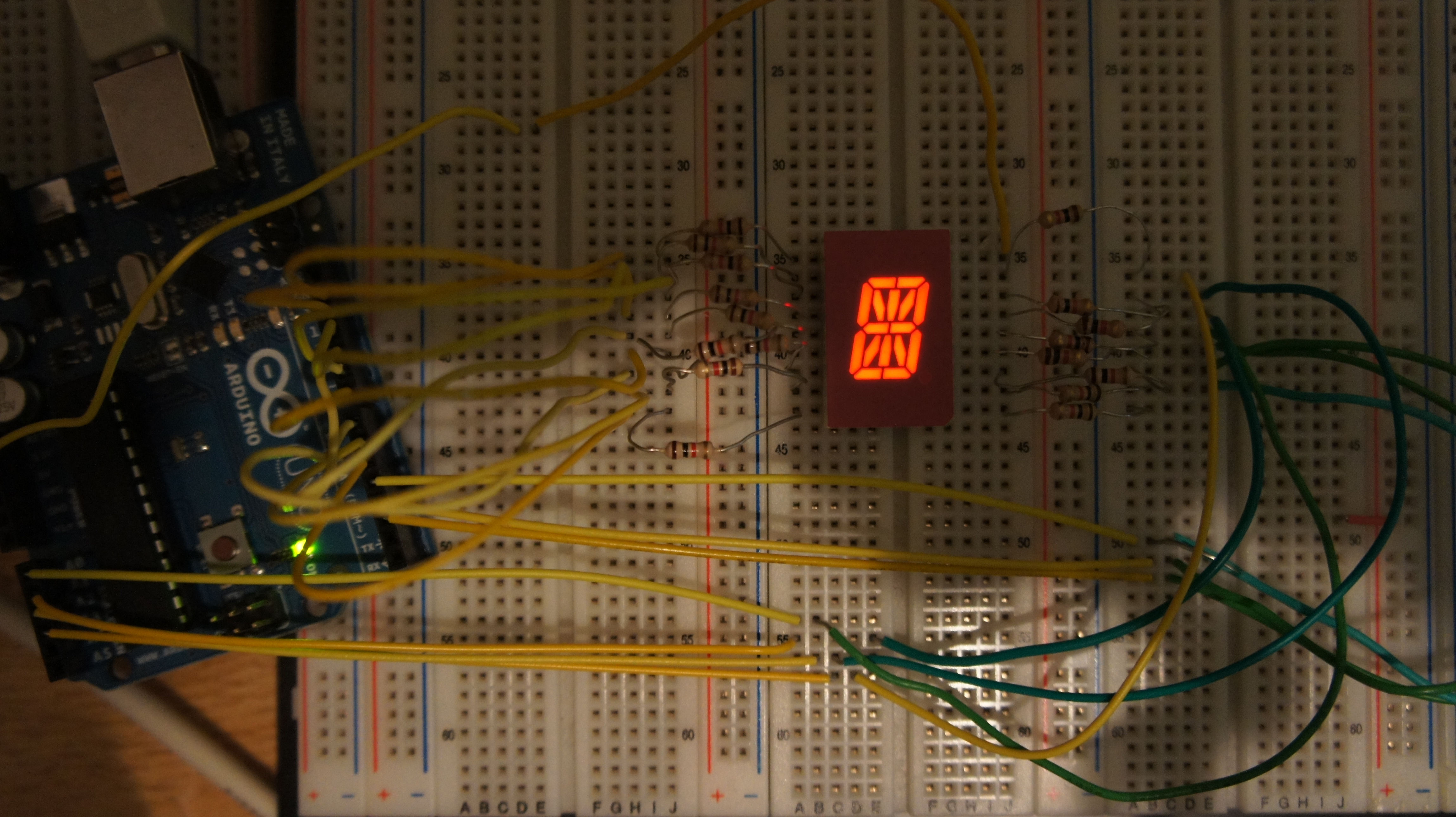
 Using a triple-sized breadboard place the display device so that it straddles the valley on the middle board.
- Using two wires, a resistor and an approriate power supply, confirm the performance of each of the 17 LEDs.
- Place appropriately-sized fixed resistors outwards from the pins of the display so that they fall onto the outer breadboards.
- Run hookup wires of sufficient length from the resistors to the pins on your Arduino according to your understanding of the mapping.
- Upload your code to the Arduino and test.
- Make necessary changes to the wiring and/or Sts.cpp library file.
 |
 |
|---|
- Once you have adapted the characters and numbers tables in the Sts library to fit our display device, the BasicUseLoop.pde driver you acquired cycles repeatedly through the tables. You are to confirm that this works as expected.
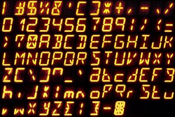
- Once completed, you will develop a second driver, DisplayDemo.pde, that showcases both your understanding of the Sts library resources and your creativity. Here are three possible avenues of pursuit,
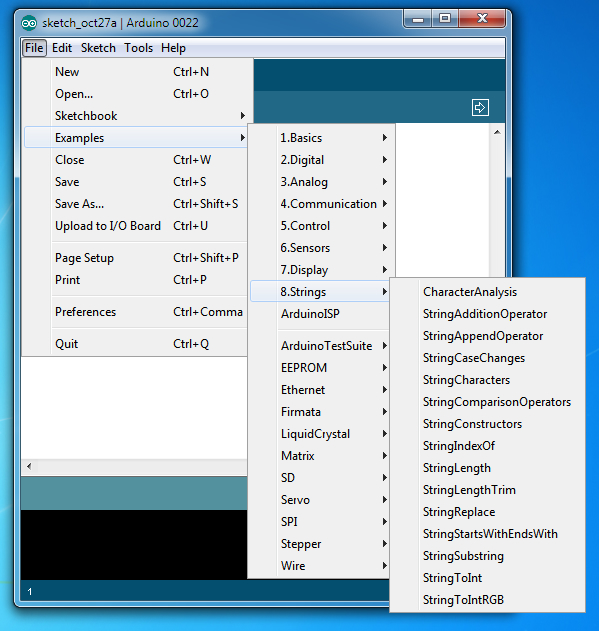
- You could display a message. The Arduino language supports a String class enabling you to make a painless migration from Java's String class. Check out the many sketches in the Strings submenu under the Examples menu to get up to speed quickly (graphic below). Also, see pp. 28-30 in your Arduino Cookbook for more code examples.
- You may wish to create a new font table for other ASCII characters. The graphic above right suggests one for the lowercase letters.
- You could develop an LED chaser in which segments are lit in sequence to display compelling patterns.
- Include corrected code (Sts.h, Sts.cpp, BasicUseLoop.pde and DisplayDemo.pde) in your ER submission this weekend and be prepared to give a demonstration on Tuesday.
- Create a new entry entitled Project 3. S.A.D. Light in Heading 1 style.
- Include Reference, Purpose, Parts List, Procedure, and Media sections (titled in Heading 3 style). Matt will provide us with a Parts List (as a well-formatted Word Table) and Photos for the Media section. The other sections are your responsibility.
Note: The highest credit will be reserved for those submissions that convince me the author understands the purpose and role of the new components introduced in this project. Be thorough and creative.
Submit by the deadline with the Subject Line: S.A.D. Light.
LED Tester. Review this author's discussion of LEDs and his design strategy for an LED Tester.
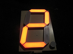
![]() Giant Seven-Segment Display. (12V switching, arrays) This assignment gives you experience using the Arduino to control a higher voltage (12V) than it can source itself (5V). In addition, you will advance your knowledge of arrays. Check out the rollover image to the right. For reference, consider this individual's experience. Alternatively, even larger DIY displays can be constructed.
Giant Seven-Segment Display. (12V switching, arrays) This assignment gives you experience using the Arduino to control a higher voltage (12V) than it can source itself (5V). In addition, you will advance your knowledge of arrays. Check out the rollover image to the right. For reference, consider this individual's experience. Alternatively, even larger DIY displays can be constructed.
Under development...
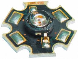
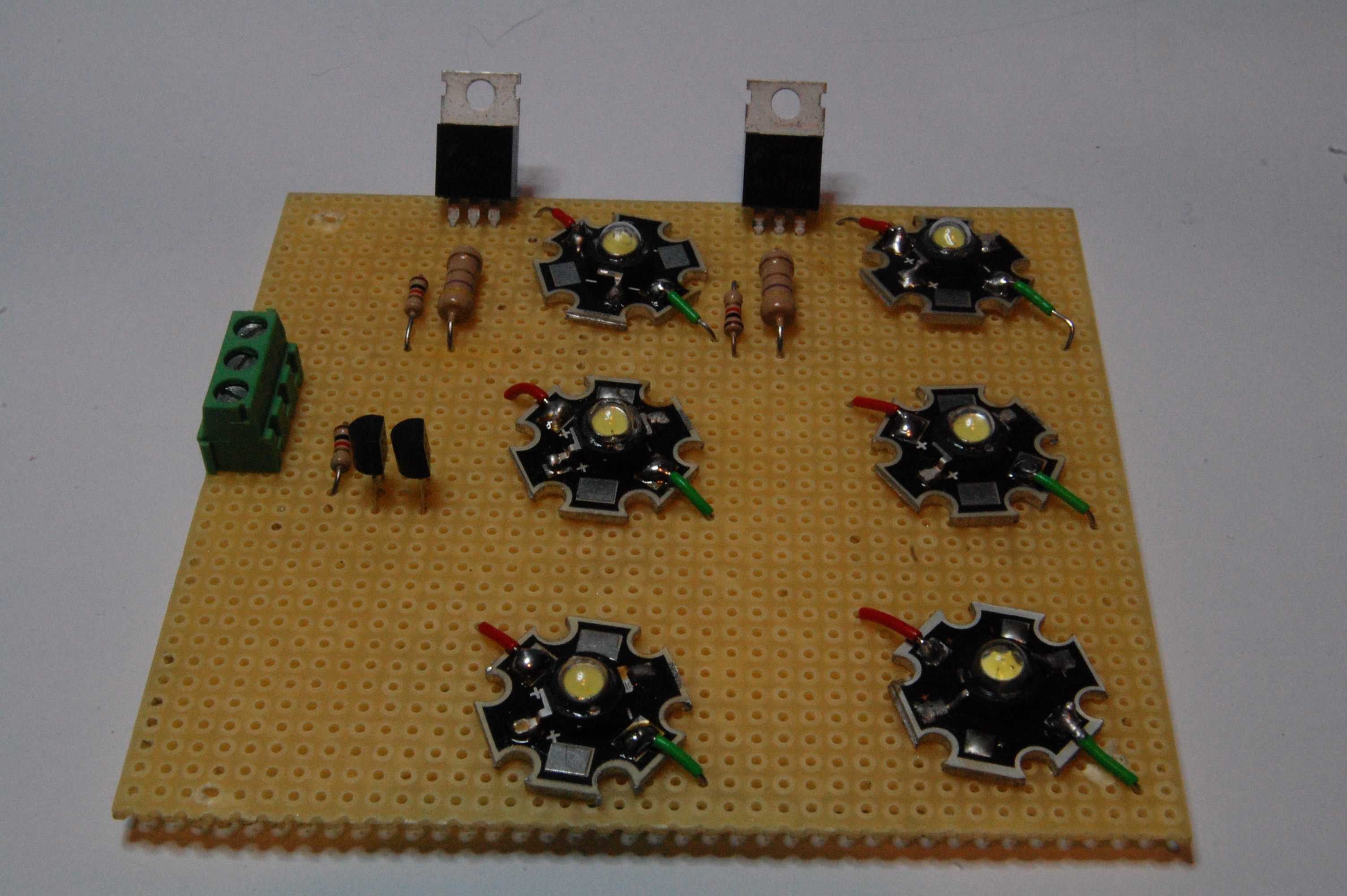
![]() High Brightness Luxeon LED. (Morse Code, 1W Luxeon, Shield Development, Soldering) For this submission you are asked to include the following sections: Purpose, Reference, Method, Sketch, Media (Detailed Photos, Video).
High Brightness Luxeon LED. (Morse Code, 1W Luxeon, Shield Development, Soldering) For this submission you are asked to include the following sections: Purpose, Reference, Method, Sketch, Media (Detailed Photos, Video).
Part of the credit I award you each week is for creativity. In the last assignment for example it would have been somewhat obvious that an image of a 3-legged BiColor LED be inserted to assist with your explanation of the new part. So, highlight the new components this week and expectations of this project (soldering a shield) with well-thought out text that is grammatically correct. Watch the spelling errors. Remember you are trying to teach!
Make sure to address all issues I highlighted in last weeks' ER.
Update your TOC.
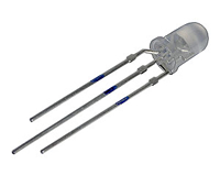
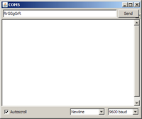
![]() BiColor LED Flasher. (3-legged BiColor LED, Serial Communications) As your first entry into your ER this year, you are asked to develop an Arduino application that flashes a Red/Green Bicolor LED in response to commands entered into the Serial Monitor. For example, the sequence RrGGgGrR would result in two Red flashes, followed by four Green flashes, followed by two Red flashes. Design for 1 s between flashes. Here's a possible sequence of tasks,
BiColor LED Flasher. (3-legged BiColor LED, Serial Communications) As your first entry into your ER this year, you are asked to develop an Arduino application that flashes a Red/Green Bicolor LED in response to commands entered into the Serial Monitor. For example, the sequence RrGGgGrR would result in two Red flashes, followed by four Green flashes, followed by two Red flashes. Design for 1 s between flashes. Here's a possible sequence of tasks,
- Review the datasheet for the BiColor LED to determine the relationship between the legs and the colour generation.
- Assemble a hardware protoype of the circuit.
- Develop and test the fully documented sketch, BiColorLEDFlasher, that demonstrates the
 capability outlined above. Be sure to incorporate as many recommended coding strategies that you can think of.
 - Insert a page break at the end of your ER, starting a new Chapter entitled, TEI3M - Arduino, in Heading 1 Style.
- Create a new entry entitled Project 1. A BiColor LED Flasher and include the following sections with appropriate content: Purpose, Reference, Method, Sketch, Media (Photos, Video(?)).
- Don't forget to update your TOC!
- Submit your ER by the deadline.
![]() Interesting Arduino Projects. The range of possible Arduino projects is literally limitless. While we'll undertake a number of projects I believe have merit, as I've already indicated, I want you to participate in selection of the projects that you find appealing.
Interesting Arduino Projects. The range of possible Arduino projects is literally limitless. While we'll undertake a number of projects I believe have merit, as I've already indicated, I want you to participate in selection of the projects that you find appealing.
The internet is loaded with sites that describe, often in great detail, projects that you should find inspiring to investigate.
By the end of this weekend (Sunday September 18) you are asked to find 5 Arduino-based projects on the internet that you might like to undertake this year. You are to include in the body of an email to handin, the name of each project, the link, and a brief statement on why you feel it has merit and/or what you find appealing about it.
Try to include a range of difficulty levels. You know enough about electronics to know what may be too simple and, possibly, too advanced. If in doubt, include it, as we may be able to scale it back somewhat.
Finally, since there are so many projects out there, that possiblilty that two students would have more than one project in common would be improbable.