TV Remote Control. Our RARM will be under wireless control. Infrared is the most pervasive strategy for control over electronic devices around us so it's a good place to start. The goal of this project is to configure a remote device capable of controlling functions of the TV in the lab.
Task. Using either a remote control device you scrounge from home, find at the curb on recycling day or a prototype assembled on a breadboard as depicted in the adjacent photo, develop the ability for thre device to manipulate the TV's On/Off, Channel Up/Dn, and Volume Up/Dn.
Robot Arm (RARM). This next (ambitious) project will be a mechanical arm under infrared control. The concept is discussed here. The authors readily admit this is a work in progress and they have no idea how to controller would work. This is where we come in!
Furthermore, the design of the acrylic components wil provide use with a perfect intoduction to CAD software, from which we can sndt the files out to be laser cut and etched. The CAD software we will be using can be found here.
In addition to the servos, we'll need to acquire a servo control board like the ones found here.
Tasks.
Confirm that you can issue three IR remote TV commands from your Arduino by modeling Project 28 from last year's workbook.
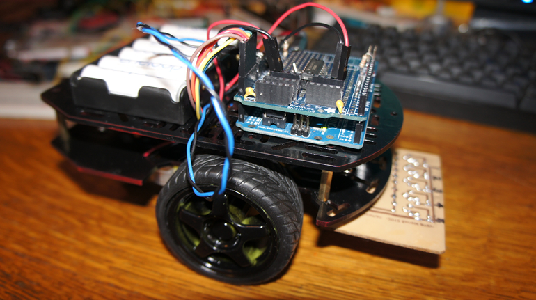
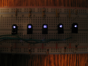
Working in pairs, configure one student's Arduino as a Transmitter (Tx) and the other student's Arduino as a Receiver (Rx). The goal is to have each of three push buttons on the Transmitter light a respective LED on the Receiver. You are encouraged to make use the documentation and sketches we reviewed in detail last class. Here is a rough prototype of the platform (I've left the missing wiring and software to you)...
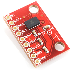
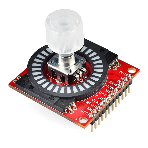
Following up on Matt's build yesterday, stabilize the base of the RARM to ensure the single servo motor in the base of the RARM comfortably drives the HIP joint. As you can see from the RARM's home page two servos drive the SHOULDER joint. Confirm the integrity of this assembly. (If after a valiant attempt the structure can't move freely, despite your best efforts, scrap the integration of the servos with the acryic and continue on without the plastic as in the video below.) Integrate the supplied Thumb Joystick from SparkFun into the mix so that a Left↔Right motion manages the RARM's HIP movement (base) and an Up↔Down motion controls the RARM's double SHOULDER joint (Kyle has experience soldering the header pins to avoid mistakes). For your sketch you may want to adapt the sketch from last year's final exam (Project 25, page 138) that makes use of the Arduino's Servo library. Accurately mapping the
values read from the analog inputs to the position angle of the servo
is the challenge. So, there's three tasks: circuit assembly, software and mechanical. Carve up the responsibilities so that the task is completed before you go home today and you demonstrate it ot me. If you do not finish by the end of class, drop by after school. I'll be in the Harkness Room until 3 pm, after which, I'll return to 302. Here's one experimenter's effort,
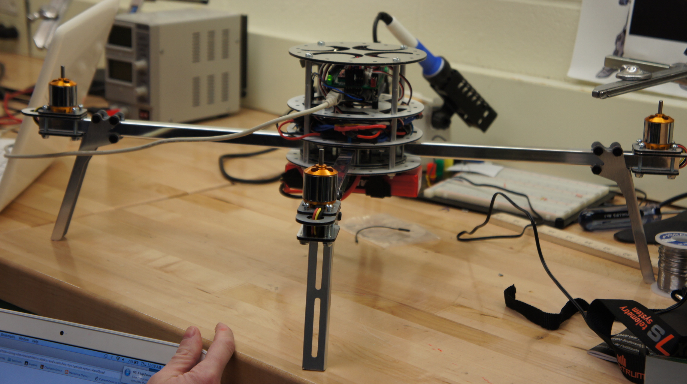
Cyclone Quadcopter. This project has been one of the intense of the year. As such it deserves a terrific, detailed writeup that you can be proud to reflect in the years to come. This wil lbe a cooperative effort.
Task.
Each ACE is asked to submit a two-page, comprehensive, Word document entitled nameQuad.doc (replace name with your name) to the TER4MForum by Sunday February 17 at midnight that provides explicit detail on your contribution to the project. (Matt: Flight Engineer, Rafe: Software Engineer, Kyle: Electrical Engineer, Justin: Mechanical Engineer)
On Monday February 18, each of you will weave the other three contributions into your own ER and submit it my midnight.
Each report will be detailed and include Purpose, Procedure, and Media Sections with on-the-fly links as required.
Your own Summary commentary will be included at the end of the 8-page entry.
This is major writeup. Get started today, collect your own media, and don't cut corners. Creative and comprehensive treatments will be rewarded.
Line Bot. The goal of this multi-stage project is to construct our first autonomous vehicle that uses a track over which it drives for navigation. The project is modelled after Linus the Line-Bot as described in Chapter 4 of Arduino Robotics by John-David Warren et al. For the chassis, we will use the Magician Chassis from Sparkfun. For power, a back of 6 Eneloop rechargeable AA battery for a combined nominal voltage of 7.2V.
Stage 1. TCRT5000L IR Sensor Bank. A collinear bank of 5 TCRT5000 IR Reflective Sensors will be used to ensure our Line Bot stays on track.
After consulting the datasheet and the internet (i.e. Badji) wire up a test circuit that takes the analog output from each sensor and display it to the Serial Monitor.
Another post by Badji describes Volga-the Line Following Robot. In the opening photo you can see his sensor board that uses 3 TRCT5000 Sensors solder to a point-to-point board. In this stage you are asked to up the ante by designing a 5-sensor layout in EAGLE that will be used to fabricate your own PCB. Here are some photos of the final results the hits and the misses. Select one or two for inclusion into your ER. Roll over the image to the right to see the display the fine board created by JA that was used in the project.
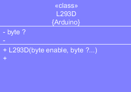
Stage 2. L293D Motor Shield. Prior to the eventual installation of the L293D Motor Shield on LineBot to drive its gear motors, it is instructive to wire up and test a simulation using simple Bicolor LEDs.
Hardware Task
Using a variety of available resources (L293D datasheet, Arduino Robotics textbook, or this guide as last resort) and the supplied components, wire up a prototype circuit with the outputs driving the Bicolor LEDs.
SAMPLE SEQUENCE
UML
STAGE
left
right
0
STOP
STOP
1
FORWARD
STOP
2
FORWARD
FORWARD
3
STOP
FORWARD
4
REVERSE
FORWARD
5
REVERSE
STOP
6
REVERSE
REVERSE
7
STOP
REVERSE
8
FORWARD
REVERSE
9
FORWARD
STOP
Software Task
(Sketch) Download the Arduino sketch L293DMotorSimulation and examine its contents. Add the remaining statements to satisfy the sample sequence above left. For this first test, run motors at full speed.
(Library) The supplied code makes use of an L293D Arduino Library we must write. After reviewing the code presented in the text and the tutorial on Writing a Library for Arduino, develop your L293D Library and drop it in the required folder. Confirm that your sketch functions as required. Here's an example of the test working,
Arduino Shield. The final task of the Motor Controller is to fabricate a Shield that will be inserted into the Arduino to controller the gear motors. A Fritzing diagram appears below left that be used as a model. Rolling over the image will result in the display of KM's great work in constructing the Shield.
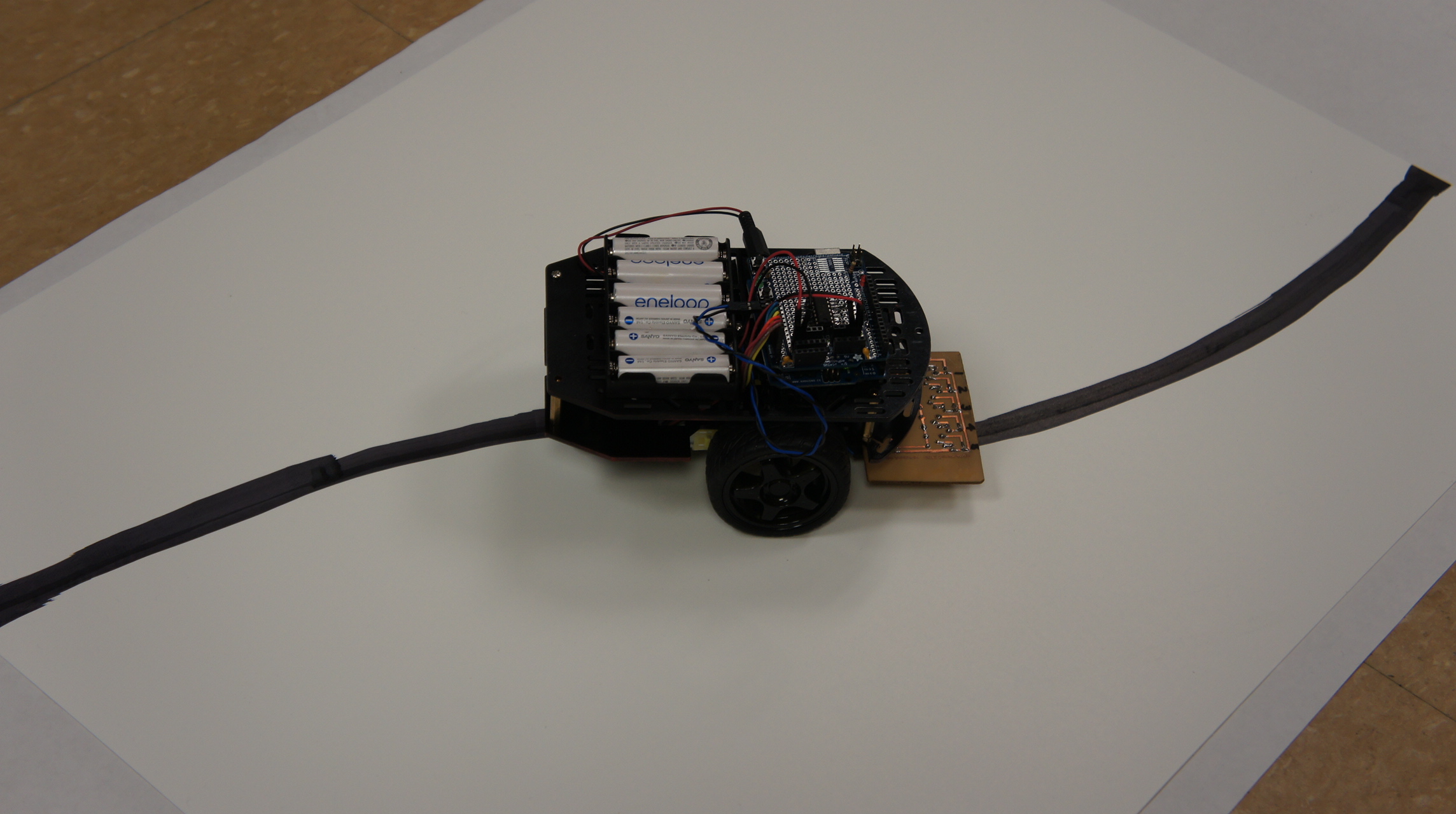
Stage 3. Line Bot Demonstration. The final assembly of our Line Bot ties together month's work of effort. With the 6-celled AA battery holder attached, the Sensor bank mounted, the Shield in place and the software modified by RB uploaded, the vehicle is ready for testing.
Mount the Line Bot off the desktop and undertake the calibration the sensors for the given lighting conditions. This requires displaying the raw and adjusted readings to the Serial monitor to modify the minimum and maximum values for the variables in the sketch. Here is the code of the latest sketch.
Using bristol board and electrical tape develop a path for the Line Bot to follow. Here's an example of our Line Bot in action,
Plot Bot. Last year's Grapher Project introduced you to the wonders of plotting curves (Cartesian, Parametric and Polar in our case). Although we're not going to undertake something as ambitious as that effort, you'll tackle the challenge of programming an autonomous rover to plot out a predetermined path. I think it's important (and fun) to put our new component, the 5V relay, to good use by integrating it with the Arduino and gear motors. This project is also designed to get you working as a team. You'll need this ability for next Spring's Robotic competition. Here's the objective...
I purchased a large pad of easel paper with grid lines. You are to work together to design, build and program an autonomous vehicle mounted with a Sharpie to plot out a square on the large graph paper. Once we get that working (hopefully) we may experiment with different plot lines.
Whereas the design and build process is a team effort, each of you will develop your own individual ER summary documenting the development cycle and outcome with special emphasis on your contribution to the team.
Task.
Given the materials provided, brainstorm the task and decide on a roughly equal division of labour that is acceptable to all members of the team.
Using the platform provided, mount a Sharpie and an Arduino that will control the two gear motors using 5V relays to control the maneuvering of the craft so that it draws out a large square on the easel paper as close to grid lines as possible.
Capture graphic images of ALL project development stages that will be included in your ER. Incorporate a selection of these photos into your ER.
You have two class periods to demonstrate your objective: plot a large square.
Submit an ER entry that includes a record of the complete development cycle by the due date. Followup: Here's the outcome!
Balloon Bot. (Based on Mechatronics for the Evil Genius. pp. 22-27). The focus of this activity is the application of gear motors to achieve a desired mechanical outcome. Since DC motors alone have rpm that are not practical for driving wheels of a vehicle that can move forward, backward and turn, gears are required to reduce the rpm.
You are asked to engineer a basic vehicle from the parts supplied (VHS case, 2 gear motors & wheels, a caster wheel and three hat pins) as well as a tethered hand controller that employs two DPDT (Mom-Off-Mom) switches to control the action of the gear motors. Your vehicle will eventually carry a balloon as its payload which it will defend in combat with the other vehicles. Round 1 of the 2012 Balloon Games appears below. See also Round 2 and Round 3.
Task (yet an other opportunity to apply your creativity)
Engineer your vehicle and controller as envisioned throughout our discussions.
Include Purpose, Reference, Parts Lists, Procedure, Media, and Conclusion Sections.
Your ER summary should include a discussion of the use of the two major components (the gear motors and the DPDT (Mom-Off-Mom) switches) a description of your design decisions and build process, as well as explaining what you would have done differently if you had to do it over again.
Gears. For this ER submission, provide your own summary of our brief look at gears and gear ratios, profiling, in text and images, your build of the TAMIYA 4-Speed High Power Gearbox as an example. The emphasis should be to express in your own words, the types of gear systems, without going into too much detail for each, with the exception of meshing pinion, idler, and spur gear trains to achieve speed reduction. Highlight your specific build of one of the configurations of the TAMIYA 72007 Kit and include a screen capture of your respective calculations within the Excel Worksheet: Gear Ratios.
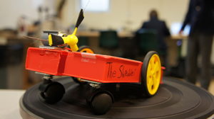
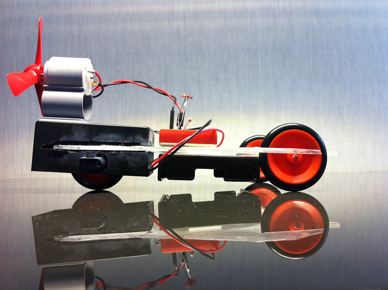
Propeller-Powered Car. For the first activity, we'll dive right into making things move. You are asked to assemble a car based on design suggested in Mechatronics for the Evil Genius, pp. 11-16. and have it ready for competition on Race Day, Thursday September 20. (One of the many fine examples engineered by the students is the one depicted to the right. Click it to enlarge)
Task.
Develop a chassis and wheels capable of carrying a rear-mounted motor equipped with a plastic propeller.
Develop the sensor/control circuit on a breadboard. When the LDR is completely covered to motor should not spin. When the cover is removed, it does at a rate proportional to the amount of light falling on its surface.
Test drive your vehicle prior to Race Day as often as it takes to ensure it will travel in a straight line across the lab in as short a time as possible.
To ensure a degree of fairness for the race, you are to utilize the parts in the table below.
Quantity
Part
Description
1
DC Motor
4.5 V, 32000 rpm
1
Propeller
4-blade plastic
4
AA Battery
1
Battery Holder
1
LDR
1
Resistor
1MΩ, 1/4W
1
TIP122
NPN Darlington Pair
Evaluation.
The credit you will earn for this project will be based on construction, race performance , and summative documentation. (ER/YouTube).
Construction (5 Marks). A premium is placed on resourcefulness, creativity and build quality for all projects when it comes to scrounging for, and assembling, parts. The effort you invest in making all parts fit together well and withstand the forces resulting from the use of your device will be assessed. Credit will be withheld for construction to the extent that you rely on me to supply for chassis parts or purchase a prebuilt units.
Race Performance (5 Marks). The car must be capable of a stationary position at the starting line. When the cover on the LDR is removed the car will advance. The winner will receive 5 marks, all finishers that cross the finish line un under 10 seconds will receive 4 marks. Cars that stay outside their lane during the race will receive a 1 point deduction for every infraction.
Summative Documentation (10 Marks). Just as you have for in the past, an ER submission is required. Standard subsections should include Purpose, Parts List, Procedure and Media. In addition to simple descriptions, a premium will be reserved this yeas for those submissions that tie physics concepts into each activity. For example, what are the variables (mass, friction, etc.) (with actual measurements if possible) that are active in each process. Finally, a compelling video seldom fails to impress as well.


 TV Remote Control. Our RARM will be under wireless control. Infrared is the most pervasive strategy for control over electronic devices around us so it's a good place to start. The goal of this project is to configure a remote device capable of controlling functions of the TV in the lab.
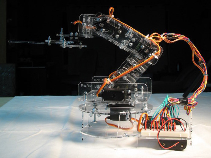
 Robot Arm (RARM). This next (ambitious) project will be a mechanical arm under infrared control. The concept is discussed here. The authors readily admit this is a work in progress and they have no idea how to controller would work. This is where we come in!
 Stage 1. TCRT5000L IR Sensor Bank. A collinear bank of 5 TCRT5000 IR Reflective Sensors will be used to ensure our Line Bot stays on track.