Project 7. The First NAND Gate Circuit
 This
is your final ER Submission for this course. Include the
following,
This
is your final ER Submission for this course. Include the
following,
- Purpose (a concise paragraph describing this activity, in your
own words)
- NAND Circuit Subsystem
- With specific reference to its At Rest and Active states, discuss
the subcircuit at the right and include the image in support of your
explanation
- Procedure
- Provide a thorough explanation of the the 4011 Quad 2-input NAND IC,
with specific reference to the action of one of its gates. Include
the graphic (bottom right) in support of your discussion.
- Photo of your circuit.
- Resistor/Capacitor Circuit
 Discussion/ Explanation in your own words
- Completed Table L19-1 (p. 73). Include this table in this writeup (Not
in Appendix A).
- Completed Question 1 from p. 77 (similar to Outline of System
at Rest p. 76)
- Completed Section Five Data Sheet (p. 77)
Update your TOC and attach your ER to an email to handin with the
Subject Line: The
First NAND Gate Circuit.
Project 6. 3D Christmas Tree
Under appropriate Heading 3 subheadings, your ER writeup for this activity
will include the following.
- A paragraph describing your kit (include a full Parts List set up as
a table, consistent with your previous table formats)
- The schematic of the 3D Christmas Tree circuit below. Since it
is quite wide, you should center-align the graphic on the page.
- A photo of your 3D Christmas Tree accompanied by a link to a video of your Tree in action,
stored in your TEL3M First Class Web Publishing folder or Personal YT channel and linked to from within your ER writeup of this Activity. Note: Be sure to include your name in the field of the video as in this sample.
- Update your TOC.
Attach your ER to an email to
handin with the Subject: 3D Christmas Tree by
the requested deadine.
Project 5. The Basic Digital Logic Gates
For this weekend's submission you are asked to,
- Insert the Word document, Inside Gates, into your ER after Project 4, retaining the landscape orientation of the document. Complete the truth tables and insert your Fritzing schematic images representing the appropriate transistor configuration underlying each gate. Finally, adjust the table shading to be consistent with your ongoing theme.
- Complete the Exercise: Integrated Circuits, CMOS ICs, found on page 75. Using your 'highly-developed' hanging indent skills, retype the questions and provide your answers for the 13 questions.
Be sure to update your Table of Contents prior to submission.
Appendix A. Tables and Exercises
The Binary Number System
Within Appendix A. Tables and
Exercises and under the subheading
The Binary Number System (in Heading 3 style) enter the questions below and supply
your answers.
- In your own words, what is the ASCII
Table and explain its purpose. Provide a link to this web site in
your ER.
- In your own words, what is Unicode and
explain why it was required. Provide a link to this web site in your ER.
- What is your surname in binary? Present your answer in a well-formatted
table.
- Translate the encoded message below into English with
the
help of the ASCII Table.
Use a well-organized and formatted table to present your results.

Here is the code in text form if you would
find
it useful. A word of advice: You could
convert the binary codes directly to decimal (Base 10) and then look them
up in the ASCII table, but you may find it easier to convert the
binary numbers
to their hexadecimal (Base 16) equivalent, and use these values to determine
the character. Not to mention the benefit of further experience with the
important hexadecimal number system.
- Question 2 on page 66.
- Question 3 on page 66.
- Question 4 on page 66.
Do not forget to update your TOC. Submit
your ER as an attachment to an email to handin with the Subject: The Binary Number System
Project X. Professional Style Alarm System
 Your writeup for this activity will include,
- Graphic of Figure
L12-7 (adjacent).
- Digital photos of the front and back of your working, soldered PCB.
- Provide a link to Figure
L12-7, the animated alarm.
- Type in the Exercise questions 1-8 from page 45 and merge in these
answers using your (pro) formatting skills. You are responsible
for understanding these supplied answers as they may be part of the future
assessments.
- Update your TOC.
Submit
your ER as
an attachment to an email to handin with the Subject: Professional Style Alarm System
Appendix B: Quizzes and Tests
Analog Review
- Insert the file Quiz3.docx into
your ER, starting on a new page following your previous Resistors quiz.
- Adapt the formatting as well as the headers and footers, to your current
ER style.
- Provide complete and accurate answers.
- Update your TOC.
- There is no need for a separate submission of this effort since Activity
4 is also due today (Saturday November 27).
Project 4. The Automatic Night Light
Your writeup for this Activity will include,
- Purpose, Reference and Procedure subsections (Heading 3 Style) with appropriate content.
- Fritzing schematic view of Figure L12-1 (right).
- Fritzing breadboard view of Figure L12-1.
- Clear photos of front and back of your soldered PCB
- Questions and your full sentence, hanging indent-laden, responses to
#'s 2, 3, 6, 7, 9, and 10 on pp. 44-47.
- (Optional) A video of the complete circuit development process and result.
Address, but do not remove, the concerns expressed
in ALL my comments embedded in your ER.docx from last submission.
Submit your ER.docx as
an attachment to an email to handin with the Subject Line: The Automatic Night Light
Project 3. The NPN Transistor
This is a major assignment.
If you use
class time wisely
to gather the necessary
data
and develop a quality submission you will be rewarded.
 Turn to page 33 and review the Exercise
based on Lesson 9. You are asked to complete this exercise as described below.
Turn to page 33 and review the Exercise
based on Lesson 9. You are asked to complete this exercise as described below.
- Starting on a new page, immediately following Project 3, include the title Project 3. The
NPN Transistor, in Heading 1 Style.
- Add the subtitle, Exercise:
Introducing Transistors in Heading 3 Style as usual.
- Insert 2 consecutive Continuous Section Breaks.
- Position the cursor between the Continuous Section Breaks and define
a 2-column format.
- Turn off Auto-Numbering.
- Insert the unformatted
questions.
- Format the questions using your hanging indent skills and supply your best,
concise formatted answers to each.
- Insert a Column Break(s) at the most strategic location(s)
to avoid orphans (a question in one place and its answer in another)
- Strategically insert your own Fritzing Schematic and Breadboard views of this Project between questions. Remember, we've modified the circuit presented in the text.
- Embed a closeup digital photo (250px wide, 1px black border) of your NPN Transistor circuit clearly showing the parts and their
connections
- Update your TOC.
After ensuring all corrections
have been addressed from your previous submission (without removing
my comments) and with Headers and Footers in place, submit your ER.docx as
an attachment to an email to handin with the Subject Line: The NPN Transistor,
by the deadline.
ER Resubmission (Optional for most). All students should address
their ER comments.
- Those students who have EVER missed
a week's submission MUST complete the assignment and resubmit
this Saturday.
- All students are invited to resubmit their corrected ERs this
Saturday for increased credit once ALL corrections have been made.
- Those students who
received
less
than 8/10 for last week's submission would be foolish not to resubmit.
Appendix B. Quizzes and Tests
To ensure your Engineering Report is as complete a study guide as possible
in preparation for the final evaluation in late January, you will insert
all the CORRECTED
quizzes and tests administered in the course into your ER.
Task.
- Insert a page break after Appendix A. Tables and Exercises
- Add the text, Appendix B. Quizzes and Tests in Heading
1 style
- Add the text, Quiz 1. Greek Alphabet in Heading 3 style
- Add a blank paragraph and then Insert Quiz1GreekAlphabet.docx,
removing the existing title that appears in Heading 1 style
- Adjust other formatting details as required
- Complete the missing entries in the table
- At the end of the table, insert a Next Page Section Break
- Switch to Landscape orientation (Page Layout menu)
- Add the text, Quiz 2. Resistors in Heading 3
style
- Add a blank paragrpah and then insert Quiz2Resistors.docx,
adjusting rulers, margins, etc. as necessary to remain consistent with the
rest of your Engineering
Report.
- Add the correct answers
- At the end of the quiz, insert a Next Page Section Break and switch back
to Portait orientation
Appendix A. Tables and Exercises
In addition to formal Activity writeups, you will be asked
to add a table of results to your Engineering Report. These tables will be
added to Appendix A that follows your Activity section.
Task.
- You are to duplicate the formatting of Table L5-1 as closely as possible
- Insert a page break after Activity 1. Measuring Voltage.
- Add the text Appendix A. Tables and Exercises in Heading
1 Style
- Add the text Table L5-1 in Heading 3 style
- Add the 8 by 5 table from page 18, centered on the page.
- Add the measurement data, center-aligned within each cell.
- Add borders and alternate background shading that will remain consistent throughout ALL your future ER tables.
Project 2. Measuring Voltage
NOTE: Substitute all references to a '9V battery' in the workbook with a 9V Adapter.
Engineering Report
- Each Project writeup starts on a new page.
- For this project subsections must include Reference (Include a hyperlink containing the URL of this project description),Theory, Procedure (complete Steps 4 to 8 ), and Conclusion.
- Develop Fritzing images similar to the ones above for inclusion in your submission and store them in your images folder.
- Appropriately-sized and formatted photos and diagrams are to be embedded at optimal locations within your writeup.
- Update your Table of Contents.
- Attach your Engineering Report to an
email to handin with the Subject: Measuring Voltage by
the required due date.
Your text should be developed in accordance with the recommendations for Technical Writing.
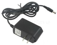
Project 1. Modifying the 9V Adapter
 You are ALL potential engineers. You must believe in yourself. For this first project, and all others to follow, please keep in mind that the quality of your work is a reflection of the respect you hold for yourself. High quality results are achievable by anyone willing to demonstrate passion and patience in their work.
A Regulated 9V AC DC adapter is better suited to our prototyping activities than 9V batteries. Disposal of the latter is problematic and battery clips snap with frustrating regularity (there's a reason they give you a half-dozen of them).
Task.
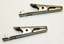 Alligator clips offer a better interface with the breadboard than the barrel jack. Using the cutting jaw of the Wire Strippers, cut cleanly through the cord, roughly 5 cm from the jack and give the end to Mr. D. These components can be reused in future projects.
- Following more detailed instructions provided in class, strip the sheathing from the power cord a further 4 cm and remove the sheathing from the red and black supply leads, 2 cm from their ends.
- Remove the red and black soft plastic covers from the alligator clips and slip them on the red and black leads, respectively.
- In addition, slip a half-length (1.5 cm) of heat-shrink tubing over each of the read and black leads.
- For each lead, slide the exposed copper through the hole in the clip and loop it around again to the jaw of the clip making sure it maintains good contact with the metal clip. Using a pair of needle-nose pliers, crimp each wing of the jaw over the wire, one at a time.
- Slide the heat-shrink tubing over the joint and, using the heat gun, shrink the tube to strengthen to the joint.
- Slide the soft plastic covers over the clip and test.
Engineering Report
Employing the best practices discussed in MIT's Technical Writing document, follow the instructions below to complete the
first entry in your Engineering
Report.
- Organization is a key to success. Create an appropriately-named folder on your laptop (i.e. Circuits, TEL3M, Hardware)
to house the files related to this course. Within this folder create a subfolder entitled images that will house all the photos and graphics you will create in this course.
- Within this folder, create a Word document entitled ER.docx.
- Follow the instructions provided in class for creating a title page, Table of Contents, and Project 1 page.
- For Project 1, include
the subsections: Title, Reference, Purpose, Procedure and Summary.
- Complete the text of each section, written in Active voice, embedding right-aligned photos that you took to document the development of the project.
- Finally, never forget to update your Table of Contents as the final action prior to submission.
- Attach your Engineering Report to an
email to handin with the Subject: Modifying the 9V Adapter by
the required due date.
Project 0. Lemon Power
Before you begin your year, you should
decide what your approach will be.
Are you a minimalist, whipping the
work off as fast as you can to simply 'get it over with' ?
Or, at the other extreme, are you prone to rambling on in
the hope that the
teacher will eventually find everything anyone
could possibly include on a topic?
My recommendation lies in the middle. Think
deeply and write economically.
A succinct,
well-conceived response will maintain your readers' attention while still
garnering the credit you're hoping for.
 Section
A. To get the juices flowing so to speak, you are asked to explore
the ability of a few simple household items, in combination, to generate
electricity. Undertake the steps outlined below and records your answers
and measurements.
Section
A. To get the juices flowing so to speak, you are asked to explore
the ability of a few simple household items, in combination, to generate
electricity. Undertake the steps outlined below and records your answers
and measurements.
- Without resorting to any form of research, what is your simplest, straightforward
explanation for the concept of electricity?
- Research the basic construction of a dry cell battery (e.g 1.5V AAA, AA,
C, D) and, in your own words, include a simple, straightforward explanation
how this kind of battery works.
- What are the two fundamental units used to quantify electricity in a circuit.
 Section
B. Despite the fact that the amount of electricity we
use in this course to power our circuits is small, it is important that it be
deployed in precise
amounts. The tool we'll use to monitor the electricity is called a Digital
Multi meter,
or DMM for short.
These are relatively expensive devices so please handle them with care.
Section
B. Despite the fact that the amount of electricity we
use in this course to power our circuits is small, it is important that it be
deployed in precise
amounts. The tool we'll use to monitor the electricity is called a Digital
Multi meter,
or DMM for short.
These are relatively expensive devices so please handle them with care.
- Turn on the DMM, position the center dial to Volts, V, and toggle the FUNC
button so DC appears on the LCD screen.
Section C. The parts you have at your disposal
include a lemon, a galvanized screw, a copper penny, two alligator clip wires,
an LED and a DMM.
- Google an image of the electron shell for Zinc. How many electrons inhabit
its outer shell? Do the same for Copper.
- Why might these observations make these elements well-suited for the promotion
of electricity?
- Explain how inserting a galvanized metal screw and a copper penny in a lemon
mimics the construction of a dry cell battery.
- Using your alligator clips and DDM probe, measure and record the voltage
of your lemon battery.
Section D. Presumably the purpose of understanding electricity
is so that we can put it to work. Typically this involves assembling a sequence
of
components that convert electricity into useful output. Each of you have been
given the same type of LED.
- Your LED is a useful device. It converts electricity into visible light.
Remembering our discussion of the design of an LED, connect it to your lemon
battery and record your observation of its behaviour.
- Is the output of your LED any different from the other students'?
- Explain how you could work with a partner to improve the output of the LED.

