The Goal
 Life involves tradeoffs and, after taking the most important ones for our purposes into consideration, it is time to set aside the Arduino IDE, in favour of ATMEL Studio 7.0 (AS7) for your embedded assembly language solutions. AS7 suite of tools offers strong support for debugging while allowing us to continue to develop on the DDP with the Sparkfun Pocket Programmer based on the USBtiny protocol. The pattern of settings side hard won skills and comfort levels is simply a fact of life within the subject domain of our choosing. Next fall will result in an entirely new set of tools and techniques thrown at you so, at the very least, the practice of leaving behind familiarity and adjusting to new realities is a lesson in itself.
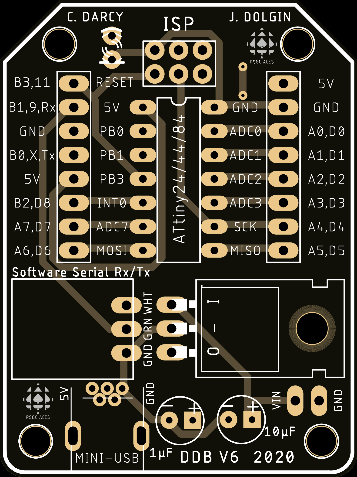
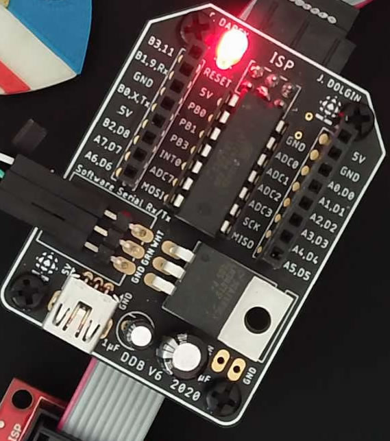
Initially, these concepts are tough-sledding but, you'll soon appreciate how happy you are to have had this introduction when your future peers are swamped a few short years from now. (DDBv6 with SoftwareSerial support appears to the right)
Key References
The sequence of exercises below have been carefully crafted for your (possible) future as a computer engineer. Commit yourself and reap the rewards.
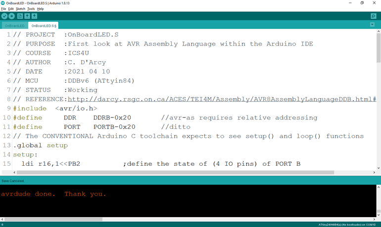
1. OnBoardLED
The Arduino IDE is a beginner's dream. It's free, facilitates straightforward project creation support, transparent access to a C-dialect toolchain, limited debugging support, and builtin Serial IO (both text and graphics) windows, to name a few assets. Furthermore, it has enjoyed wide global adoption for well over a decade, spawning broad reference and tutorial support.
ICS4U-E ACES, however, have moved beyond entry-level requirements of the Arduino's ATmega328P MCU and are looking to undertake deeper exploration and optimization of an 8-bit MCU as they lay their solid foundation for post-secondary engineering coursework. To accomplish this effectively, in any field for that matter, one's tools must evolve in step the craftsman's skills and needs.
So, imagine it's Monday April 26, 2021 and one or more ICS4U-E ACES did not manage to migrate to a functioning Windows/ATMEL Studio 7 platform on which to explore AVR 8-bit Assembly Language on the DDBv6. You have a collective decision to make. Do you leave them behind and continue on, or do you remain within the (limited) Arduino IDE and do the best you can knowing everyone is equally engaged? This is your call (by Sunday April 18th - I need a week of prep) as your teacher will prepare for either outcome for your 10-class Session 8 Assembly Language experience.
By way of introduction here is the briefest of demonstration sequences for either IDE you choose for our AVR Assembly Language development requirements.
 Arduino IDE
- Open the Arduino IDE and create an Arduino project entitled OnBoardLED
- Delete the entire contents of the (BareMinimum-based) OnBoardLED.ino file
- Close the Project
- Download the file OnBoardLED.S into the OnBoardLED project folder
- Reopen the Project and click on the OnBoardLED.S tab
- Review the file and using your AVR Pocket Programmer, ''Upload Using Programmer' to confirm
- Listen carefully to the comprehensive explanation to follow
or, you have decided, collectively, we will push on to a more professional/supportive IDE.
ATMEL Studio 7
 Using Finder, create a folder to store your AVR Assembly Language projects
- Launch Atmel Studio 7
- Select File>New>Project
- Select Assembler | AVR Assembler Project and complete the dialog box using OnBoardLED as the Project's name and browsing to the folder created in Step 1 as the Location
- In the Device Selection dialog, choose ATtiny84 and continue
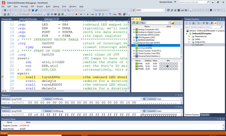
- The project is now created with the driver file entitled, main.asm.
- Close the project and replace the default main.asm with this main.asm
- Reopen the project and review the file, awaiting further execution instructions.
2. Data Location, Addressing, and Movement
 The previous example provided an introduction to the IDE and a glimpse of digital IO instructions. For this highly compressed study at AVR 8-bit Assembly I have chosen to introduce data and memory-related instructions and techniques early on in your assembly journey. New AVR instructions include ldi, lpm, st, cp, and out.
One concept to pay particular attention to in this discussion is the notion of the RAM Stack. To put it succinctly, a stack is a system- and user-accessible LIFO-based temporary storage repository. We'll make use of this area in Step 5 of this sequence.
Task.
- Create an AVR Assembly Project for the DDBv6 entitled MemoryExample.
- Replace the default main.asm code with the one below,
;PROJECT :MemoryExample
;PURPOSE :Data Location, Access, and Copying from PROGMEM to SRAM
;AUTHOR :C. DArcy
;DATE :2021 04 27
;DEVICE :Dolgin Development Platform
;MCU :ATtiny84
;COURSE :ICS4U
;STATUS :Working
;REFERENCE :https://mail.rsgc.on.ca/~cdarcy/Datasheets/doc0856.pdf
;IDE :ATMEL Studio 7
;.include "prescalars.inc" ;assembly directive equivalent to compiler directive #include
.def util = r16 ;readability is enhanced through 'use' aliases for GP Registers
.def trgt = r17
.equ DDR = DDRA ;typically, we will need the use of PortA
.equ PORT = PORTA ;both its data direction register and output register and, eventually,
.equ PIN = PINA ;its input register
; DATA Segment declarations
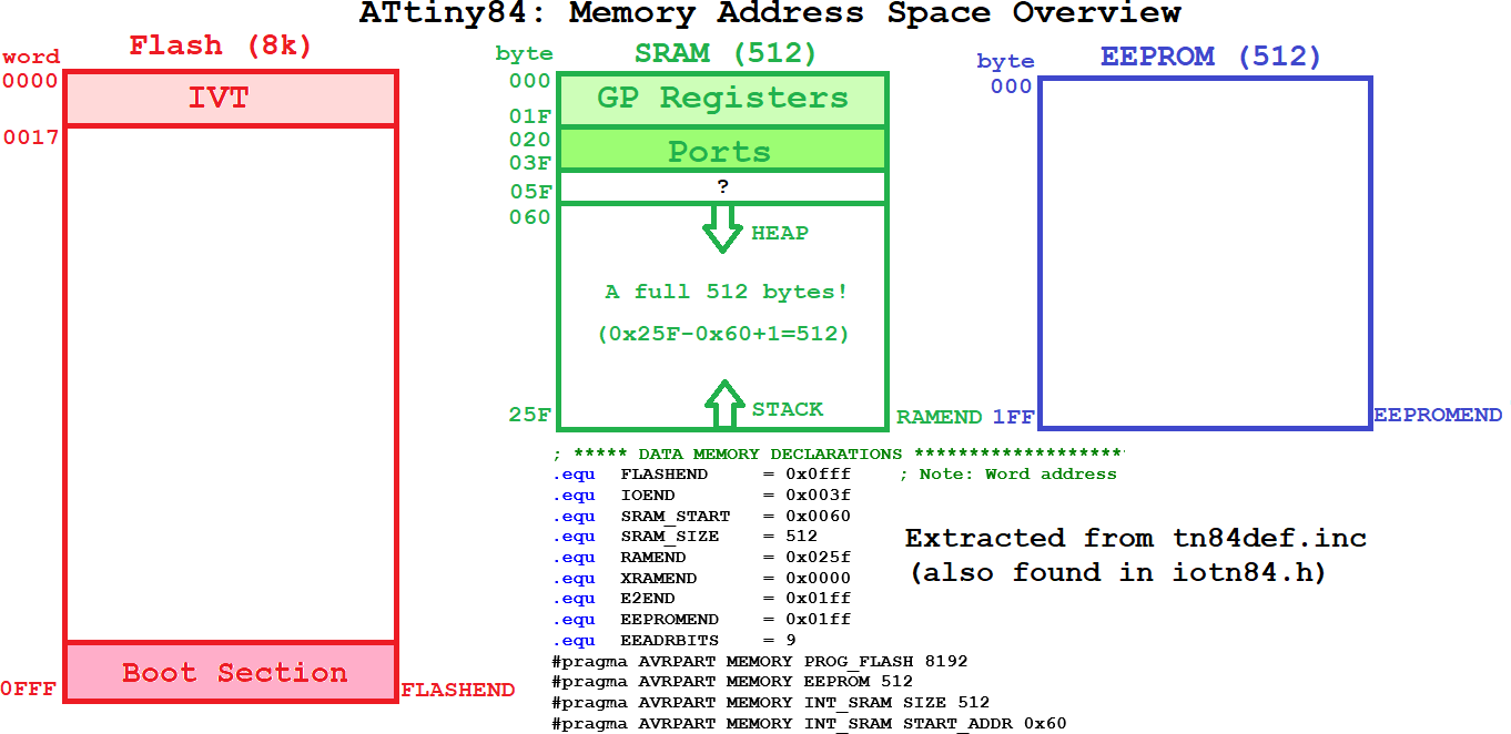
.dseg ;locate for Data Segment (SRAM) requirements (default start at 0x0060)
.org SRAM_START
var: .BYTE 1 ;reserve one byte for a variable (the label is the symbol)
arrayStart:
.BYTE 10
arrayEnd:
; CODE Segment (default)
.cseg ;locate for Code Segment (FLASH)
; ***** INTERRUPT VECTOR TABLE ***********************************************
.org 0x0000 ;start of Interrupt Vector Table (IVT) aka. Jump Table
rjmp reset ;lowest interrupt address == highest priority!
.org EXT_INT0addr ;External Interrupt Request 0 (prefined in tn84def.inc)
; rjmp INT0_vect
.org INT_VECTORS_SIZE ;free to continue after the IVT
segStart: ;address of the start of table of constants in progmem
.db 0B00111111, 0B00001001, 0B01011110, 0B01011011
.db 0B01101001, 0B01110011, 0B01110111, 0B00011001
.db 0B01111111, 0B01111001
segEnd: ;marks the end of the table
; ***** START OF CODE ********************************************************
.org 0x0100 ;well clear of IVT and possible table definitions
reset: ;PC jumps to here (start of code) on reset interrupt...
ldi util,low(RAMEND) ;ensure the Stack Pointer points to the end
out SPL,util ;of SRAM to ensure maximum stack size
ldi util,high(RAMEND) ;This is technically not necessary as the
out SPH,util ;assembler does it for us, but it's good practice
PROG2RAM:
ldi ZL,low(segStart<<1) ;create a pointer to the start of the table in progmem
ldi ZH,high(segStart<<1);high byte of (word-size) pointer address
ldi YL,low(segEnd<<1) ;create a pointer to the end of the table in progmem
ldi YH,high(segEnd<<1) ;high byte of (word-size) pointer address
ldi XL,low(arrayStart) ;create a pointer to the target address in RAM for copying
ldi XH,high(arrayStart) ;high byte of (word-size) pointer address
next:
lpm util,Z+ ;load byte from progmem into a regsiter (and autoincrement)
st X+,util ;copy register contents to RAM address (with autoincrement)
cp ZL,YL ;are we done? (source pointer address at end of table)
brne next ;if not, keep going...
halt:
rjmp halt ;hold (or repeat)...
- Listen carefully to the detailed discussion of the program.
Blink
The blink sketch is the MCU's version of "Hello, World!".
Let's develop it from 'scratch'.
- Place an LED in the DDBv6 spanning digital pin 0 (anode) and the adjacent ground location.
- Using the default ASM Assembler Project Template as a base, create the project, Blink.
- Remove ALL contents of the main.asm file so we can start from nothing.
- follow the discussion...
3. BareMinimumDDBv6 Assembly Language Template
To get us started, we'll use the code shell below. It has little more than we need, but this stuff can be tricky so better to remove what's not needed than struggle to get it to cooperate.
;PROJECT	:BareMinimumDDBv6
;PURPOSE	:Code shell for AVR Assembly projects for the DDBv6 (ATtiny84)
;AUTHOR		:C. DArcy
;DATE		:2021 04 26
;DEVICE		:Dolgin Development Platform
;MCU		:ATtiny84
;COURSE		:ICS4U
;STATUS		:???
;REFERENCE	:https://mail.rsgc.on.ca/~cdarcy/Datasheets/doc0856.pdf
;IDE		:ATMEL Studio 7
;.include	"prescalars.inc"	;assembly directive equivalent to compiler directive #include
.def		util	= r16		;readability is enhanced through 'use' aliases for GP Registers
.equ		DDR		= DDRA		;typically, we'll need the use of PortA
.equ		PORT	= PORTA		;both its data direction register and output register and, eventually,
.equ		PIN		= PINA		;its input register
; DATA Segment declarations
.dseg							;locate for Data Segment (SRAM) requirements (default start at 0x0060)
var:		.BYTE 1				;reserve one byte for a variable (the label is the symbol)
; CODE Segment (default)
.cseg							;locate for Code Segment (FLASH)
; ***** INTERRUPT VECTOR TABLE ***********************************************
.org		0x0000				;start of Interrupt Vector Table (IVT) aka. Jump Table
	rjmp	reset				;lowest interrupt address == highest priority!
.org		EXT_INT0addr		;External Interrupt Request 0 (predefined in tn84def.inc)
;	rjmp	INT0_vect
; ***** START OF CODE ********************************************************
.org		0x0100				;well clear of IVT
reset:							;PC jumps to here (start of code) on reset interrupt...
	ldi		util,low(RAMEND)	;ensure the Stack Pointer points to the end
	out		SPL,util            ;of SRAM to ensure maximum stack size
	ldi		util,high(RAMEND)   ;This is technically not necessary as the
	out		SPH,util            ;assembler does it for us, but it is good practice

wait:
	ldi		util,0xAA
	sts		var,util
	rjmp	wait				;repeat or hold...
Activity: Project Template Creation in 3 Steps
Step 1.  First, we need to create and explore an assembly code shell that will serve a role similar to the
 BareMinimum sketch we used repeatedly in the Arduino IDE.
- Open AS7 and create a New AVR Assembly Project in your DDP
Assembly folder with the name BareMinimum84.
- Within the Device Selection dialog, select ATtiny84.
- Use the code above to replace the default
main.asm code supplied and listen carefully as we review it.
- Under the Project menu, select the BareMinimum Properties option and select the Tools button. Select Simulator as the debugger/programmer.
- Select the main.asm tab, launch the Debug menu and select, Start Debugging and Break.
- Now, simply marvel at what comes next...:)
- Within the Solution Explorer panel to the right, select the Dependencies folder and double click the
tn84def.inc file to review the complete list of .equates available to your assembly code. You are encouraged to maximize their use.
 Step 2. Next, we need to confirm we can upload code from AS7 to the DDP with your Sparkfun Pocket Programmer.
- Watch this video:
 Using a USBtiny Programmer with Atmel Studio
- Here's the web tutorial of the video: http://www.crash-bang.com/using-usbtiny-with-atmelstudio/
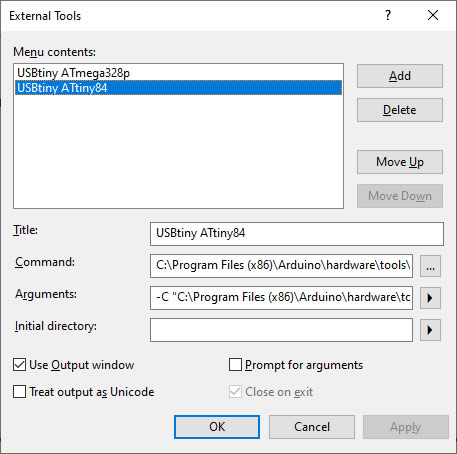
- Under the Tools Menu, select External Tools... and build a USBtiny ATtiny84 tool that will create a script to convert and upload our assembly source file to the ATtiny84 target on the DDP. Click the image to the right to enlarge. On my Windows version I have,
Title: USBtiny ATtiny84
Command: C:\Program Files (x86)\Arduino\hardware\tools\avr\bin\avrdude.exe
Arguments: -C "C:\Program Files (x86)\Arduino\hardware\tools\avr\etc\avrdude.conf" -c usbtiny -p t84 -v -v -v -U flash:w:$(TargetDir)$(TargetName).hex:i
Step 3. Finally, AS7 provides a seamless method for creating new projects from an existing code shell.
-
After saving
main.asm, select Export Template... under the File menu.
- Select Project Template and then complete the fields in the subsequent dialog box, entering
BareMinimum84 as the Template Name.
- Feel free to use the adjacent ACES ASM graphic for your Icon Image, and select Finish when complete.
- With luck, the next project you create can be based on your
BareMinimum84 template, providing a more productive use of your time and effort.
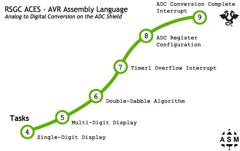
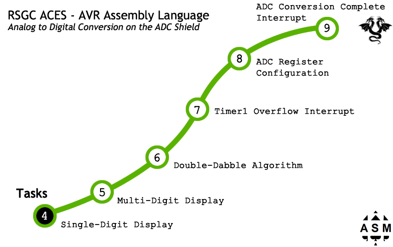
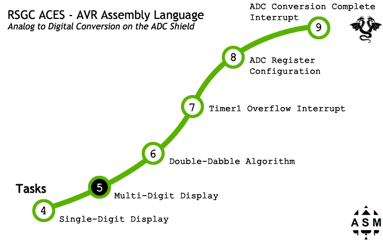
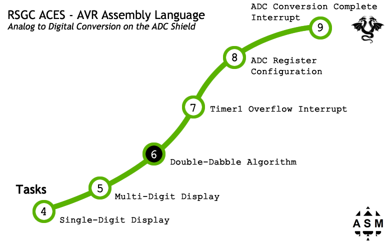
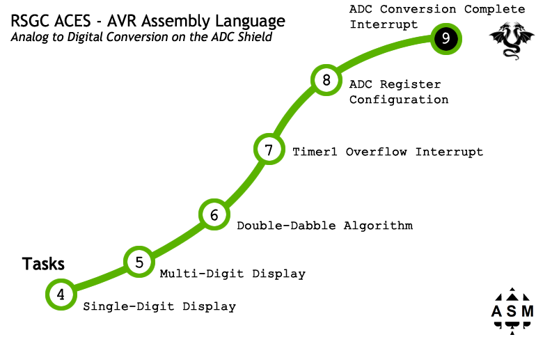
The goal for Session 8 (April 26 - May 7) is to introduce you to Assembly Language in preparation for undergraduate exposure, typically in second or third year (or possibly even first year at Waterloo- ECE150). The optimum way I can think of to accomplish this is to adapt your facility with the DDP's ADC Shield using Arduino C through the use of AVR Assembly Language, exclusively. As the graph below suggests, the plan is to break this down into daily increments as shown in the progression path below.
4. Shiftout: 7 Segment (Single-Digit Display - Using the ADC Shield)
 With a degree of awareness of the ATMEL Studio IDE established combined with an understanding of the Assembly project organization and custom template in place, we can now consider implementing a familiar function within the new Assembly environment, more or less from scratch.
Task.
 Assemble your DDP (DDBv6+ADC Shield)
- Using your BareMinimumDDBv6 as the template, create the AVR Assembler project, Shiftout7Segment.
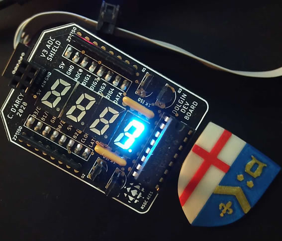
- Adapt the opening comments to reflect the purpose of this project which is to cycle, continuously, through the 10 decimal digits on the ADC Shield's units' display.
- Among other .equates and .defines, include the lookup table (LUT) of the 7-segment map from a recent project.
- The goal is to create an assembly version shiftout function that mimics an MSBFIRST loading of the 74HC595 shift register enabling the cycling through of the segment maps from the LUT.
- Follow along carefully as we develop this project together.
; PROJECT    : Shiftout7SegmentSingle
; PURPOSE    : Indirect Addressing to present a digit sequence on a single
;            : 7-segment display on the ADC Shield DDP (ATtiny84)
; AUTHOR     : C. Darcy  (apostrophe omitted for web presentation)
; DATE       : 2021 04 26
; DEVICE     : Dolgin Development Platform (DDBv6 + ADC Shield)
; MCU        : ATtiny84
; COURSE     : ICS4U
; STATUS     : Working (as of 2021 04 16)
; REFERENCE  : Example: http://www.nongnu.org/avr-libc/user-manual/assembler.html
; REFERENCE  : https://mail.rsgc.on.ca/~cdarcy/Datasheets/doc0856.pdf
; IDE        : Arduino
#include <avr/io.h>
//based on example above, trying to avoid C Compiler directives, as in
//#define  util  r16  ;seems to be problematic for other inexplicable reasons anyway
util  = 16          ;readability is enhanced through (use) aliases for GP Registers
value = 17          ;holds the value to be displayed
mask  = 18          ;byte with one set bit to act as a mask
dir   = 19          ;shift direction: LSBFIRST:0, MSBFIRST:1
n     = 20          ;define a register to hold the value shifted
DDR   = DDRA-0x20   ;typically, we will need the use of PortA
PORT  = PORTA-0x20  ;both its data direction register and output register and, eventually,
PIN   = PINA-0x20   ;its input register
active= PA4         ;pick one display to make active (PA1-PA4)
DATA  = PA5         ;595s data pin
LATCH = PA6         ;595s latch pin
CLOCK = PA7         ;595s clock pin
FLAGS = 1 << active | 1 << DATA | 1 << LATCH | 1 << CLOCK
LSBFIRST = 0        ; same familiar constants from Arduino days
MSBFIRST = 1        ; ditto
.section  .text     ; leave it like this for now (more efficient to put it in SRAM with .data but)
;******** LookUp Table (LUT) of 7 - Segment Maps **********
segStart:           ; MSBFIRST: ABCDEFGx
.byte   0b11111100, 0b01100000, 0b11011010, 0b11110010
.byte   0b01100110, 0b10110110, 0b10111110, 0b11100000
.byte   0b11111110, 0b11110110
segEnd:
; ***** START OF EXECUTABLE CODE *************************************************
.org  0x0100                 ;some references consulted suggest this is N/A
.global main                 ;no sense using setup() and loop() at this level
main:
  ldi   util,  FLAGS         ;load the ORed flag set for output pins
  out   DDR,   util
  sbi   PORT,  active        ;turn on the active (units) display
  ldi   XL,    lo8(segStart) ;position the 10 - bit registers
  ldi   XH,    hi8(segStart) ;  to the start ...
  ldi   YL,    lo8(segEnd)   ;  and the end ...
  ldi   YH,    hi8(segEnd)   ;  of the array of segments (aka. LUT)
; ready to shift digit, simply request shift order: either LSBFIRST or MSBFIRST
  ldi   dir,   MSBFIRST      ; ABCDEFGx order and ADC Shield requires MS
repeat:
  movw  Z,X                  ; position Z at the start of the LUT
next:
  lpm   n,Z+                 ; obtain the next segment map and autoincrement
  rcall shiftout             ; invoke the shiftout function
  rcall delay1s              ; admire...
  cp    ZL, YL               ; are we at the end of the array ?
  brne  next                 ; if not, keep going...
  rjmp  repeat               ; if so, start all over again...
  ret                        ; never reached

;---------Shiftout Function------------------------------------------------
shiftout:                    ; shifts constant n into the 595
  ldi  mask, 0x80            ; assume order is MSBFIRST
  sbrs dir, 0                ; if bit 0 is set, it is MSBFIRST
  ldi  mask, 0x01            ; OK, it is LSBFIRST so redefine the mask
  cbi  PORT, LATCH           ; pull LATCH pin LOW
again:
  cbi  PORT, CLOCK           ; pull CLOCK pin LOW
  mov  value, n              ; reload the value to be presented
  and  value, mask           ; mask off the target bit
  breq lo                    ; was it 0 ?
  sbi  PORT, DATA            ; no, so pull DATA pin HIGH
  rjmp clockit               ; ready to clock the 1
lo:
  cbi  PORT, DATA            ; else, it was a 0, so pull DATA pin LOW
clockit:
  sbi  PORT, CLOCK           ; pull CLOCK pin HIGH
; hmmm, must decide what direction to shift the mask...
  sbrs dir, 0                ; if bit 0 is set, it is MSBFIRST
  rjmp shiftLeft             ; OK, it is LSBFIRST
  lsr  mask                  ; MSBFIRST so shift the mask right
  brne again                 ; repeat if there are still more bits to stuff in
  rjmp done                  ; we are done, so only one more thing to do
shiftLeft:
  lsl  mask                  ; LSBFIRST, so shift the mask left
  brne again                 ; repeat if there are still more bits to stuff in
done:
  sbi  PORT, LATCH           ; pull LATCH pin HIGH to present 595's internal latches on output pins
  ret                        ; finished, return.

;---------delay Function------------------------------------------------
;http://darcy.rsgc.on.ca/ACES/TEI4M/AVRdelay.html
delay1s:
; Assembly code auto - generated
; by utility from Bret Mulvey
; Delay 8 000 000 cycles
; 1s at 8.0 MHz

ldi  r21, 41
ldi  r22, 150
ldi  r23, 128
L1:
dec  r23
brne L1
dec  r22
brne L1
dec  r21
brne L1
ret
5. Shiftout: 7 Segment (Multi-Digit PoV Display - Using the ADC Shield)
 The ultimate goal of Session 8 is to establish a degree of familiarity with AVR Assembly language. I believe this is best achieved through the reproduction of your previous high-level functionality on the DDP's ADC Shield. With the previous segments code in place to shift out the map for a single 7-segment display, we now apply our well-established PoV skills to a multi-digit display using a lower-level approach.
After completing the task, I created animated gifs to provide a sense of this stage's PoV objective. In the sequence below a photo of each of the four digit frames were captured and the states assembled together using 50 ms, 20 ms and 0 ms frame delays, respectively. Your PoV solution would result in no dectectable delay between frames, of course.
Task.
- Maintain your assembled DDP (DDBv?+ADC Shield)
- Open the previous project, Shiftout7SegmentSingle, and place the entire conttns of main.asm to the Clipboard (Ctrl-A, Ctrl-C), before closing the project.
- Using your BareMinimumDDBv6 as the template, create the AVR Assembler project, Shiftout7SegmentMulti.
 Replace the entire template code with the contents of your Clipboard (Ctrl-A, Ctrl-V). Build the project and confirm by uploading it to your DDP.
- Adapt the opening comments to reflect the purpose of this project which is to present the hard-coded values of 3, 2, 0, and 1 (a sample of a possible future ADC read → Double Dabble) on the four 7-segment displays.
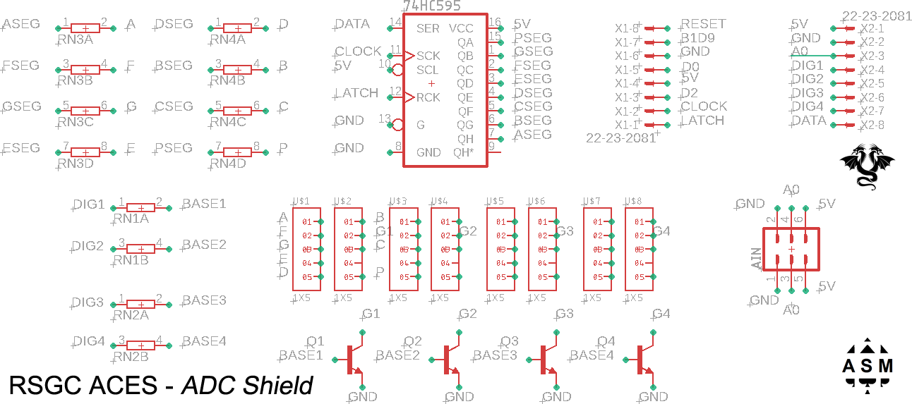
- The key to this stage is to exploit your facility with the shiftout function in conjunction with synchronizing it with strategic manipulation of the pins attached to the respective base pins. Click on the schematic to the right to confirm the wiring of the IO and transistor base pins.
- Follow along carefully as we develop this project together.
 6. Double Dabble - Shift/Add 3 Algorithm (Binary to BCD Conversion)
The primary goal of our final four instructional days (May 25-28) is to achieve a significant end to our all-too-brief exploration of AVR Assembly language; something we can both be proud of. Realistically, getting all the way to Step 9 will be a challenge but that's what we're all about.
Pre-Task.
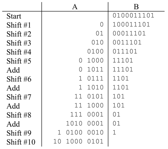 Prior to Tuesday, I would like you to find time to review the Double Dabble (aka Shift/Add3) Algorithm in three forms,
- The first is in the form of the worksheet (DoubleDabble.docx) we undertook together with pencil and paper that was first posted to the conference on March 17. Attached again for you convenience. See if you can remember how to execute the algorithm again that converts a decimal number to its BCD form.
- A register-level C version of the Double Dabble algorithm written to demonstrate both a byte to BCD3 conversion and a word to BCD5 conversion.
- Finally, creators of hardware and software products typically produce informative material in the form of pdf application notes. ATMEL produces hundreds of AppNotes that are rich with insights and techniques. One such paper (AVR204.pdf) speaks directly to BCD conversion algorithms that we'll loosely follow next week. Although it takes a little practice and effort to gain comfort with these Notes, they have the power to shorten project development time in the long run due to their insights and optimization.
Knowledge of these three assets will simplify our collective implementation of the AVR Assembly version that will serve you well in third year.
Task. (new Assembly Instructions: lsl, rol, cpi, brlo, andi, add)
- We'll confirm the Double Dabble algorithm in isolation first. Use your DDB AVR Assembly Template to create a DoubleDabble project.
- Update the opening comments and add the equates indicated below.
.equ		cTHREE		=0x03	;convenient constants to add if required
.equ		cTHREEZERO	=0x30	;
- Add the following defines,
.def		util		=r16	;readability is enhanced through the use of aliases for GP Registers
.def		count		=r17	;holds the number of shofts remaining
.def		bin0		=r18	;binary LOW byte
.def		bin1		=r19	;binary HIGH byte
.def		BCD01		=r20	;BCD: 2 least significant BC digits
.def		BCD23		=r21	;BCD: middle BC digits
.def		BCD4		=r22	;BCD: 1 most significant BC digit
.def		three		=r23	;assign the constant 0x03
.def		threeZero	=r24	;assign the constant 0x30
- At the opening of your code, be sure to position the Stack Pointer at the end of SRAM. This may be done by default (debug to confirm) but it's a good practice to do it explicitly.
- As you recall, there are conditions that would require the addition of 3 to either the low nibble or high nibble over the course of the algorithm. To facilitate these eventualilties, load the two relevant equates into their respective registers.
- Add statements to initialize the register pair bin1:bin0 to the word-size reading constant. (Recall the low() and high() macros). (Hint Z-pointer and lpm instruction)
- Create the function (label plus ret) bin2BCD16: Since the purpose of this project is to perform the Shift/Add3 algorithm into the BCD4:BCD23:BCD01 register triple, it is required that these registers be zeroed to begin with. Within the function, at the outset clear these registers and initialize the count register to 16 (the required number of shifts).
- Listen intently as we develop the remainder of the algorithm together....
7. Timer 1 Overflow Interrupt (ATtiny84 - Using the ADC Shield)
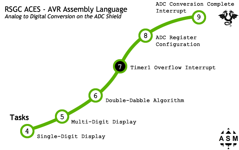 It may seem odd to insert a segment on a Timer Overflow interrupts in the midst of a sequence dedicated to the development of ADC handling, but let me explain. Timers and Counters are the backbone of embedded systems as they are ideal for scheduling events. ADC are typically subject to intervl schedullng.
Continuous A/D conversions (free-running mode) is appropriate if immediacy is critical and that's all your MCU is doing. However, tying up resources exclusively for this one task is otherwise, wasteful. Alternatively, the ADC can be configured to undertake a conversion when triggered by a variety of external events. One of the options is a Timer Overflow event.
Another dividend of this segment is to revisit a similar topic developed earlier in the course: the reusability of common code in the form of include files (.inc) accessed from outside the current project.
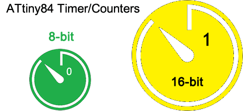 In this segment you will explore how you can configure a Timer/Counter to generate an interrupt at regular intervals (in a later segment we'll include code within the ISR to request an A/D conversion be started). The ATtiny84 has two timers. Timer 0 maintins and 8-bit counter and Timer1 is a 16-bit counter. We'll make use of Timer 1 as it offers greater flexibility. We'll design it for 1s interrupt intervals. For confirmation, our overflow ISR will simply toggle the DDB's onboard LED (PB2), resulting in a 2 Hz frequency.
Task. (new Assembly Instructions: sei, sbi, cbi)
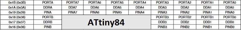
- Chapters 13 and 14 of the ATtiny84 datasheet cover the Timer/Counters. A summary of the registers appears below. Ignore the green rectangle as I'm borrowing the image from another project.
- To achieve this we'll configure the ATtiny84's only 16-bit Timer/Counter (Timer1) to fire every second and confirm.
8. ADC Register Configuration (ATtiny84 - Using the ADC Shield)
 References
9. ADC Conversion Complete Interrupt (ATtiny84 - Using the ADC Shield)
 TBD...
Exercises
Bicolor Confirmation
For the exercises below, before we add the AVR Assembly complexities of serial IO, we'll find it simpler to have a bicolor LED (spanning the digital pins PA0 and PA1) to signal digital 0 or 1 or the success (or failure) of a particular assembly programming test.
Let's explore what it takes to display the two different colours on the bicolor LED. See ATtiny84 Register Summary.
- Within your DDP
Assembly folder, create a project called BicolorConfirmation, based on your BareMinimumDDBv6 template.
- Place the bicolor LED in the DDP digital pins 0 and 1.
- Within the
main function, declare digital pins 0 and 1 only, for output.
- Add functions
red, green, and LEDOff functions that achieve their expected results.
- Add code to the
reset function to confirm the correct performance of the three functions.
- Recall you can create code and access a
delay function as you did earlier in the course (AVR Delay Loop Calculator).
If..then..else Statement in AVR Assembly
- Review the details in the April 7th post to our subject conference
- Familiarize yourself with the AVR instruction: cpi (compare with immediate) See pg. 81 in this Instruction Manual
- Watch this video If..then..else Statement in AVR Assembly (10:28) prior to me coming online for our Meet. You'll find this a familiar review.
- Use these concepts and skills in this week's Bicolor Byte project.
Iteration: While
- Watch this video The While Statement in AVR Assembly
Iteration: For
- Watch this video The For Statement in AVR Assembly
Variables (FLASH and SRAM)
- Watch this video Data, Labels, Stack, and Registers in AVR Assembly