| 2010-2011 TEI4M Engineering Interfacing Tasks |
Coil Gun. By mutual agreement, it has been decided that we will undertake the investigation and development of a coil gun. Both students will develop their own apparatus enabling each to concentrate on their own preferences (DC's interest in the mechanical aspects and JG interest in the software monitoring aspects)
DC Task 1:
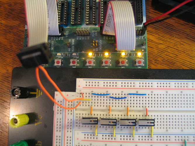
- Quick Prototype development
 JG Task 1:
- LCD Programming
- ATmega16 External Interrupts (Video)
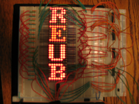
LED Matrix: Final Submission. You final ER submission for your LED Matrix project will include,
- Purpose
- Procedure
- Parts List
- Schematics
- EAGLE Mask
- Media: Photos and Video
 LED
Matrix
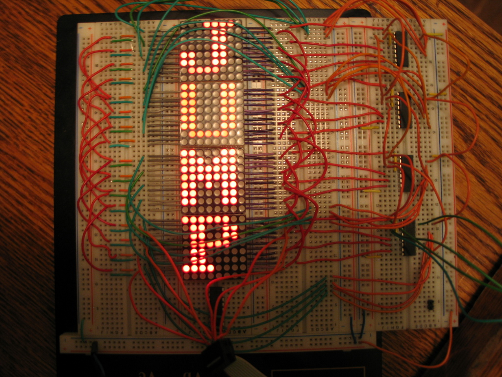
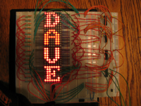
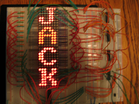
11. Build. View the Jump Scroll Video.
LED
Matrix
11. Build. View the Jump Scroll Video.
 LED
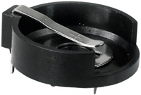
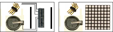
Matrix 10. EAGLE. An alternative to a 5V DC wall adapter
for your power source could be the dual CR2016 lithium coin
battery
holder, delivering 6V.
LED
Matrix 10. EAGLE. An alternative to a 5V DC wall adapter
for your power source could be the dual CR2016 lithium coin
battery
holder, delivering 6V.
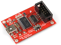
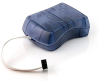
LED Matrix 9. ISP.The ability to burn new code into a μC already embedded in a system is useful. This is referred to as In-System Programming, or ISP for short. You have been given an AVR programmer which uses the ISP6 function (6 pins) to enable in-system programming of your ATmega16. Further details on this device can be found at www.sparkfun.com. This requires the use of third party software (AVRDude). An alternative is the AVRISPmk2 from AVR pictured to the right. The advantage to this device is its seamless integration with AVRStudio4.
PGM-09825 uses AVRDude
|
AVRISPmkII uses AVRStudio4
|
 |
 |
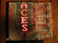
LED Matrix 8. Shift Registers. Using the serial interface of the HEF4749B Shift Register, your code can insert bit-by-bit SRAM buffer data into the multi-block string of LED Matrix units as the video FlashingAces.avi demonstrates.
 |
 |
 |
 |
LED Matrix 7. SRAM Buffer. With the LUT data in EEPROM, character data can be retrieved and placed in an SRAM buffer. Storage and retrieval commands for SRAM are ld and st respectively. Here's a good one-page tutorial on manipulating data in SRAM.
Task.
- Create the project LEDMatrix7 and adapt previous code to retrieve the character data from EEPROM for each character in your messeage and store them in SRAM starting at 0x0060 (SRAM_START). Use AVRStudio's memory simulation capabilities to confirm the transfer of byte data from EEPROM to SRAM is taking place.
- Once the message data is loaded into the SRAM buffer, display the characters, one at a time, on your LED Matrix.
 LED
Matrix A. (DC) Project Concept. Submit your ER with a Project
description of your concept, a version 1.0 EAGLE Layout design and a full Parts
List. Below is the pinout for the ISP connector. Consult the ATmega168
summary for the location of these pins.
LED
Matrix A. (DC) Project Concept. Submit your ER with a Project
description of your concept, a version 1.0 EAGLE Layout design and a full Parts
List. Below is the pinout for the ISP connector. Consult the ATmega168
summary for the location of these pins.
LED Matrix 6. EEPROM Sequential Access. (From Wikipedia) "EEPROM (also written E2PROM and pronounced "e-e-prom," "double-e prom" or simply "e-squared") stands for Electrically Erasable Programmable Read-Only Memory and is a type of non-volatile memory used in computers and other electronic devices to store small amounts of data that must be saved when power is removed, e.g., calibration tables or device configuration."
The ATmega16's EEPROM is the ideal storage location for your font LUT developed in LED Matrix 4. With 512 bytes available you have room to store up to 64 glyphs (letters, digits, punctuation, icons, etc). This has the effect of sectioning out LUT data into a separate file (.eep extension) that can be burned into EEPROM (not Program Flash).
Task.
- Create the project, LEDMatrix5, and copy the code from LEDMatrix4.
- Precede the font LUT with the Assembler directive, .eseg and follow it with the .cseg directive.
- Assemble the project and confirm the .eseg usage statistics (208 bytes) in the Build panel at the bottom of the AVRStudio screen.
- Burn LEDMAtrix5.eep into EEPROM.
- Read over ATMEL's Appnote, AVR100: Accessing the EEPROM
- Edit the code to retrieve the necessary font data from EEPROM using the process defined in the Sequential Read section of the Appnote. This involves the manipulation of a number of EE-secific I/O registers (EEARH and EEARL, EEDR, and EECR). To support your effort here is sample assembly code taken from page 23 of the ATmega16 datasheet.
- Debug and test.
LED Matrix 5. Random Access. In completing LED Matrix 4 you have confirmed your ability to access your font set sequentially. In this stage, random access must be demonstrated. Add the following code,
MSG:
  .db	"RANDOMACCESS"
MSGEND:
Task. For each character in the message, first determine its offset from 'A', as in,
 	lpm	segment,Z	; obtain next character to be displayed
	ldi	temp,'A'	; A(65)
	sub	segment,temp	; determine offset into alphabet
then by multiplying this result by 8 (three lsl's will do it), the address of the starting byte (segment) of the character in the font table can be determined.
 LED
Matrix 4. Glyphs. This stage incorporates the display
of ASCII characters using 8x8 character font set. Since there isn't one built
into the AVR, we have to create one. But how? Creating your own font requires
a lot of effort, but it can be done. You could use pencil & paper and some
graph paper to define the byte data for a LUT or you can use a font
editor
such
as
the
one developed
for Excel at this
Instructable site. Alternatively, you could search the internet for a predefined
one, as I did in turning up this one, developed
for a different assembler. Notice the eighth row and have been left
blank to ensure a space between glyphs (characters).
LED
Matrix 4. Glyphs. This stage incorporates the display
of ASCII characters using 8x8 character font set. Since there isn't one built
into the AVR, we have to create one. But how? Creating your own font requires
a lot of effort, but it can be done. You could use pencil & paper and some
graph paper to define the byte data for a LUT or you can use a font
editor
such
as
the
one developed
for Excel at this
Instructable site. Alternatively, you could search the internet for a predefined
one, as I did in turning up this one, developed
for a different assembler. Notice the eighth row and have been left
blank to ensure a space between glyphs (characters).
Task. Encode an 8x8 font set of the uppercase letters of the alphabet into a LUT in program flash using a font of your choosing. Develop code to display the 26 letters, one after another, on your LED Matrix with 1-second delay between glyphs. To get you started, feel free to use the character LUT definitions I used in the LED Matrix 8 video.
 LED
Matrix 3. Diagonals (Timer Interrupt). You
have
successfully
employed
cycle-eating
delay
routines
in projects before. Indeed, reducing the delay in your LED Matrix 2 code produces
the illusion
of
a persistent diagonal. However, the problem with do-nothing loops is, exactly
that, the microcontroller does nothing. What if the μC could do something
useful while it's waiting for a period of time to end? The answer is it can,
and it involves a technique known as interrupt-driven programming.
LED
Matrix 3. Diagonals (Timer Interrupt). You
have
successfully
employed
cycle-eating
delay
routines
in projects before. Indeed, reducing the delay in your LED Matrix 2 code produces
the illusion
of
a persistent diagonal. However, the problem with do-nothing loops is, exactly
that, the microcontroller does nothing. What if the μC could do something
useful while it's waiting for a period of time to end? The answer is it can,
and it involves a technique known as interrupt-driven programming.
Task. Configure the Timer0 Interrupt to support continuous switching between diagonals as shown in the animation to the right.
 LED
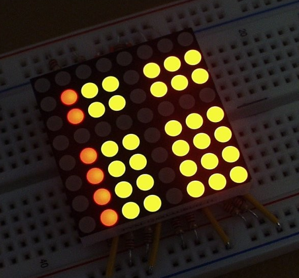
Matrix 2. Single LEDs.
Here's
what we're possibly aiming for. (An AVR driven scrolling
message board is a terrific project. It involves multiple stages,
full of important concepts along the way that will translate well to all
sorts of other projects in your future).
LED Matrix 1 lit full rows or columns. In this stage you'll light one LED
at a time, on the diagonals. Lighting a pattern of single LEDs requires
careful consideration of the sequence of respective combinations of anode
and cathode pins.
LED
Matrix 2. Single LEDs.
Here's
what we're possibly aiming for. (An AVR driven scrolling
message board is a terrific project. It involves multiple stages,
full of important concepts along the way that will translate well to all
sorts of other projects in your future).
LED Matrix 1 lit full rows or columns. In this stage you'll light one LED
at a time, on the diagonals. Lighting a pattern of single LEDs requires
careful consideration of the sequence of respective combinations of anode
and cathode pins.
Task. Examine the animated gif I've prepared to the right. For the regular pattern I've chosen, it would be possible to duplicate it by simply rotating bits. However, given the stages ahead, I'd ask you to use a Look Up Table (LUT) as a source for your cathode data. Whether you choose a LUT or rotation instructions for your anode data is up to you for this stage.
Create a project called, LEDMatrix2 and duplicate this pattern on your CC 8x8 LED Matrix.
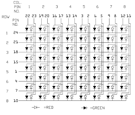
LED Matrix 1. Mapping. For your first project, you are asked to manipulate an 8x8 bicolor (red and green) LED matrix component (click image to enlarge). The pin assignments for your common cathode LED matrix appear below (the side marked YS should be facing upwards). Familiarize yourself with the addressing of the matrix by manually sampling the pins at 5V with suitable resistance.
 |
 |
 |
Task. Create the project LEDMatrix1 for the ATmega16 that
drives your 8x8 bicolor LED matrix to produce the pattern I've prepared in
the animated gif appearing above right. Click to see a
video clip of the sequence. Adapt
this ATtiny24
code that implements a lookup table strategy you should employ. It would
be a good idea to famialiarize yourself with the following Assembler instructions:
ror,rol,lsr, and lsl.
LED Research Project. Please find time to familiarize yourself with the pages below...
Project Preferences.
| DC | JG |
Tesla Coil |
|
Fibre Optics |
LED matrix "Rubiks Cube" |
LED sign |
|
LED matrix |
|
LED Cube |
Plasma Ball or Tesla Coil |
Analog
LED Clock (nice site) |
Microphone attachment for Altoids speaker (Altoids megaphone) |
G-Force motion sensor (a device that measures forces and provides data on an LCD screen) |
LED Cube 2. In version 2 of your LED Cube project, you are asked to incorporate a Timer0 Interrupt strategy to assist in achieving a 'Persistence of View' (or PoV) in a new pattern of your own creative design.
Your pattern should include distinct time intervals in which pairs or triples of LEDs within different levels and columns appear to be on simultaneously as part of a pattern of esthetic appeal.
Note 1: You will be asked
to construct a standalone desktop model, so give your pattern some thought.
Note 2: Could you figure out a way to offer more than one pattern
to users of your desktop model?
 LED
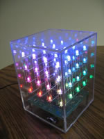
Cube 1. You've agreed that the LED
Cube is an
appropriate starting point for this year's course. I agree, as it gets us into
designing, building and simple testing right away. Review this PDF outline
for an idea of where we're headed. Search the web
under LED Cubes and study the various approaches that others have
employed.
LED
Cube 1. You've agreed that the LED
Cube is an
appropriate starting point for this year's course. I agree, as it gets us into
designing, building and simple testing right away. Review this PDF outline
for an idea of where we're headed. Search the web
under LED Cubes and study the various approaches that others have
employed.
- Using the supplied material (graph paper, plywood, drill and bits), create the jig folder holding the LEDs for soldering.
- Solder up each level, testing as you go.
- Solder the three levels together
- Test the assembly and make any necessary corrections.
- Final Manual Testing
- Take photos and videos
- Assembly language review
Over this period you will develop firmware that will light each of the 27 LEDs in a sequence of your own design. Delays between LED lightings should be a multiple of 0.5 seconds. For your ER writeup entitled LED Cube 1: Delay Loop, please include the following sections,
- Reference (include a link to the instructable)
- Purpose (your words)
- Procedure (your words)
- Code (include a fully formatted and commented listing in Courier 9-10 point
- Media (include a photo and link to video taken on Friday)