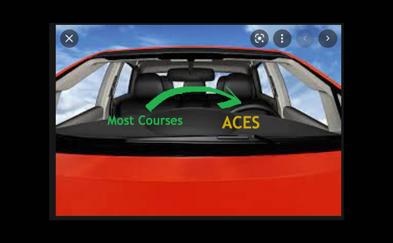
Independent Study Projects. Please read our overview on why ACES pursue Independent Study Projects so vigorously.
2026-2027 TEJ4M Independent Study Projects (ISPs) |
Independent Study Projects. Please read our overview on why ACES pursue Independent Study Projects so vigorously.
| Grade | Contribution to Final Mark |
|---|---|
11 |
40% |
12 |
40% |
For the bulk of your formal education you have been, and will continue to be, required to consume curriculum chosen for you by someone else. Hopefully you will put this knowledge and skill to good use in your future. However, jumping through someone else's hoops no longer secures future success. For that, you must put yourself in the driver's seat while in secondary school to both cultivate and demonstrate your own unique initiative, motivation, and passion. RSGC ACES program is explicitly built and tailored for you to foster these greater goals. Yes, there is much to learn but there are so many great projects to be undertaken and noble problems to be identified and solved that offer stimulating contexts within which to develop and refine your interests it will quickly seem more than worth the risk, effort, and cost.

 To my mind, the characteristics of a great project include such aspects as imagination, creativity, a degree of risk and, sometimes, even simplicity, to name a few. Check out the flashlight circuit 'board' this guy made out of little more that a piece of paper and a pencil? Simple, but inspiring.
Consider a problem that needs a solution. Boyan Slat did at age 17 when he was in high school; four years later he is
 cleaning up the world's oceans. (Update: January 9, 2019) So, dig in, think, dream, research, and explore possible project pursuits. Be discerning: don't accept the first thing that comes along. You'll be expected to maintain the progress of your ISP on your web page to enable everyone to follow your efforts so have your phone handy to at all times to capture the images of your journey. Be conscious of the fact that a multi-page summary of your project will appear in your DER after Presentation Day for more permanent record of your efforts. You may wish to take into account the ISP Evaluation document that will be applied on your Presentation Day.
Also, don't underestimate the value of an enterprise/entrepreneurial aspect to your project that could see a number of units of your project in the hands of future ACES, for sale in the Dragon's Lair or beyond, reaching an even a broader audience.
The 7 Ps of a Successful ISP...
Preparation > Proposal > Prototyping > Preview > Production > Presentation > Publication
2026-2027 Independent Study Projects
| ACE | ISP.Long (20%) Saturday October 31 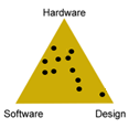 |
ISP.Medium (20%) Saturday February 6  |
|---|---|---|
| Proposals | ISP.Long Proposal |
ISP.Medium Proposal |
Araujo, A. |
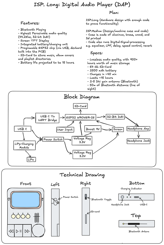
Digital Audio Player (DAP)
MCU ESP32 WROOVER-IE DESIGN A PCB will be designed in easyEDA to mount all of the components together, allowing for a functional final product. The case will be designed in Fusion 360 and Machined using a mill and lathe. The PCB will be manufactured by JLCPCB COMMUNICATION Serial (to program and debug the ESP32), SPI (to communicate with IC such as DAC and screen), Bluetooth (to connect to headphones) MECHANICAL N/A |
??
DESCRIPTION MCU HARDWARE SOFTWARE DESIGN COMMUNICATION MECHANICAL |
Bawa, T. |
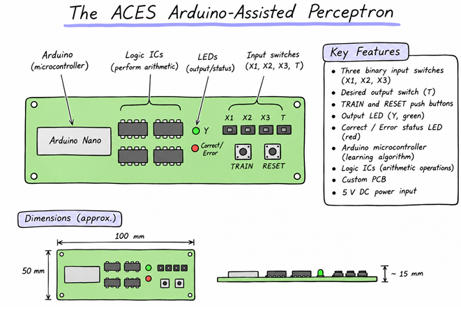
ACES Arduino-Assisted Perceptron
The device will have three input switches, a switch for selecting the desired output, and a training button. When the perceptron produces an incorrect output, the Arduino will adjust the stored weights, allowing the circuit to learn from its mistakes. Through repeated training, the device will be able to learn different logical functions, such as AND, OR, and majority, without changing its wiring. The project will use binary adders and shift registers to perform the arithmetic operations, while the Arduino controls the learning algorithm. Once completed and tested on a breadboard, the circuit will be transferred to a custom PCB and housed in a 3D-printed enclosure.MCU 328p (Nano R3) DESIGN The breadboard prototype will be converted into a PCB with identical function, designed in EasyEDA and manufactured by JLCPCB. The PCB will be mounted in a 3D-printed encasement, designed in Fusion. COMMUNICATION This project will use SPI for communication between the Arduino and shift registers. The project will also use serial communication through USB for debugging and monitoring the perceptron’s weights and training progress. MECHANICAL This project will not feature any motors or moving mechanical components. |
??
DESCRIPTION MCU HARDWARE SOFTWARE DESIGN COMMUNICATION MECHANICAL |
Clark, N. |
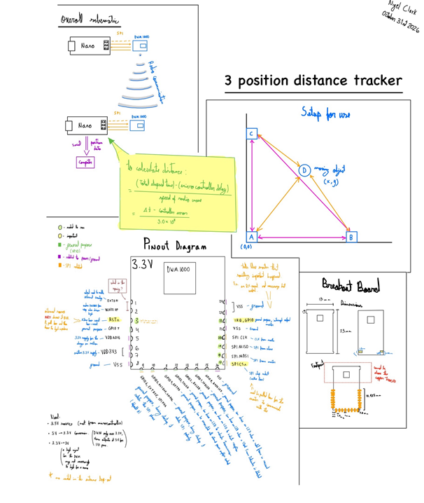
Three Position Distance Tracker
MCU Nano ESP32 DESIGN I will use EasyEDA to design a PCB for my device, this is crucial because the radio modules I have can only be surface mounted, this means that the first step of my project is creating a breakout board for the module. If time allows I may also create a cleaner final device that is fully surface mounted. COMMUNICATION The Nano will communicate with the DWM1000 using SPI communication. The DWM modules will communicate with each other using RF. MECHANICAL There are no mechanical details to this project. |
??
DESCRIPTION MCU HARDWARE SOFTWARE DESIGN COMMUNICATION MECHANICAL |
Denton, N. |
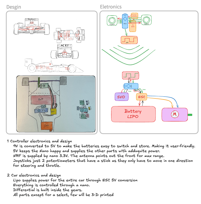
RC Formula Car
MCU Arduino Nano R4 and Nano ESP 32 function as R4 (?) DESIGN Fusion 360, easyEDA, JLCPCB. COMMUNICATION RF MECHANICAL Brushed motor, servo, Joysticks, buttons, switches |
??
DESCRIPTION MCU HARDWARE SOFTWARE DESIGN COMMUNICATION MECHANICAL |
Graves, M. |
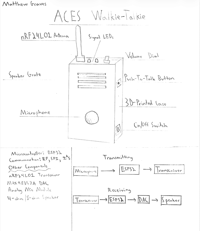
ACES Walkie-Talkie
MCU ESP-32 Nano BLE/WiFi DESIGN EasyEDA and JLCPCB will be used for the design and production of custom PCBs for this project. Furthermore, Fusion360 will be used to design a custom 3D-printed case for the walkie-talkie. COMMUNICATION SPI communication will be used to connect the nRF24L01 transceivers to the microcontrollers. The transceivers will communicate with each other via RF, providing wireless communication between devices. The microcontroller will output digital audio data to the DAC via I2S communication. MECHANICAL N/A |
??
DESCRIPTION MCU HARDWARE SOFTWARE DESIGN COMMUNICATION MECHANICAL |
Jamal, J. |
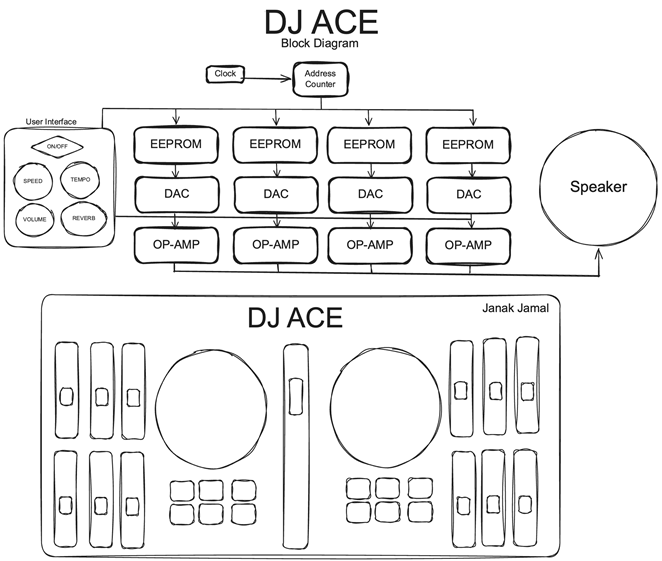
DJ ACE
MCU 328p DESIGN This project will feature PCB design using EasyEDA and an 3D printed enclosure, designed using Fusion. COMMUNICATION These projects using serial communication to drive an LCD display. MECHANICAL This project will feature rotary encoders, mechanical switches, potentiometers and other user interfaces to rewind, speed up/slow down the track, change volume and emphasize specific instruments or parts of the song. |
??
DESCRIPTION MCU HARDWARE SOFTWARE DESIGN COMMUNICATION MECHANICAL |
Koutsaris, E. |
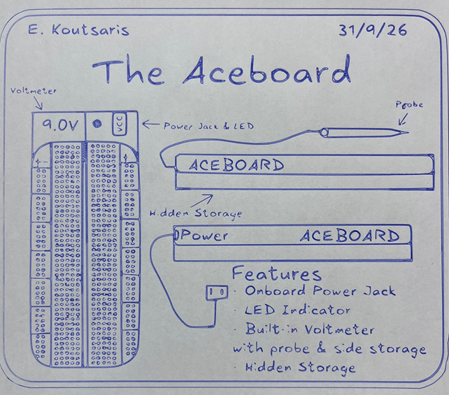
ACEboard
MCU None DESIGN The various versions of the ACEboard will be designed in fusion and printed on my bambu lab a1 3D printer using PLA filament COMMUNICATION None MECHANICALMy project will feature a voltmeter to display input voltage, a power jack along with an LED power indicator. |
??
DESCRIPTION MCU HARDWARE SOFTWARE DESIGN COMMUNICATION MECHANICAL |
Lamb, Z. |
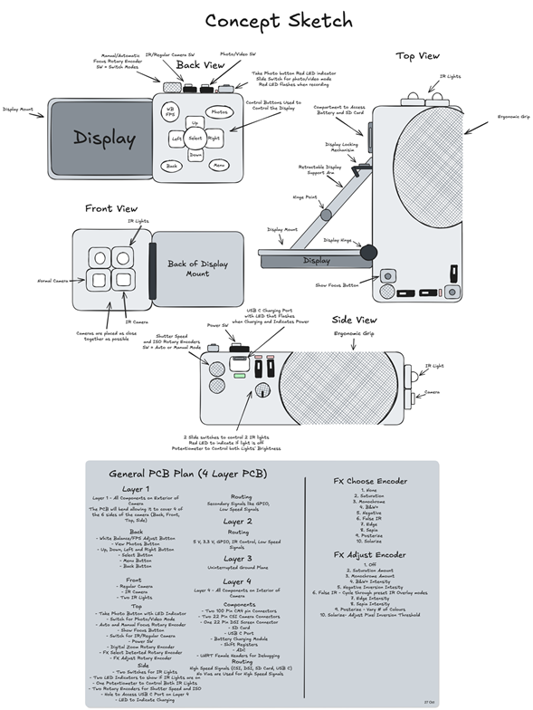
Multispectral Handheld Camera
MCU Raspberry Pi Compute Module 4, 2 GB Lite DESIGN Although the Multispectral Handheld Camera will have a 3D printed case, it will be completed in the ISP Medium submission and will be explained in that proposal. The PCB will be designed in EasyEDA. The PCB will be a rigid-flex PCB. On 3 of the 4 sides of the PCB there will be two flex sections, each being bent at a 45º angle to create a 90º angle allowing components to be placed on both the top and side of the camera. The PCB will be a 4-layer PCB, with the 1st layer being for the exterior of the camera featuring buttons and rotary encoders to take photos, adjust the display and more. The 2nd layer will be for GPIO routing, 5 V, 3.3 V and other secondary signals. The 3rd layer will be an uninterrupted ground plane. The 4th layer will feature the SMD connectors for the Raspberry pie, CSI connectors for the cameras, DSI connector for the display, multiple shift registers to maximize GPIO pin usage, an ADC, and more. A more detailed plan of what will appear on each layer of the PCB appears in the sketch. The sketch has been populated with the majority of the components that will be used in this project; however, the placement of the components is not final. Various test points will be placed to allow for easy debugging as a breadboard prototype will not be made. Potentially, acrylic will be used on the exterior of the camera and will be discussed in the ISP Medium proposal. COMMUNICATION The two cameras are controlled through I2C. The shift registers will be controlled through SPI. The shift registers are used to maximize the GPIO pin usage on the Raspberry Pie, as it only has 28 built in GPIO pins, which will not be enough for the planned features. There will also be Serial communication female headers on the 4th layer of the PCB to allow for easier debugging. MECHANICAL N/A |
??
DESCRIPTION MCU HARDWARE SOFTWARE DESIGN COMMUNICATION MECHANICAL |
Malkani, Z. |
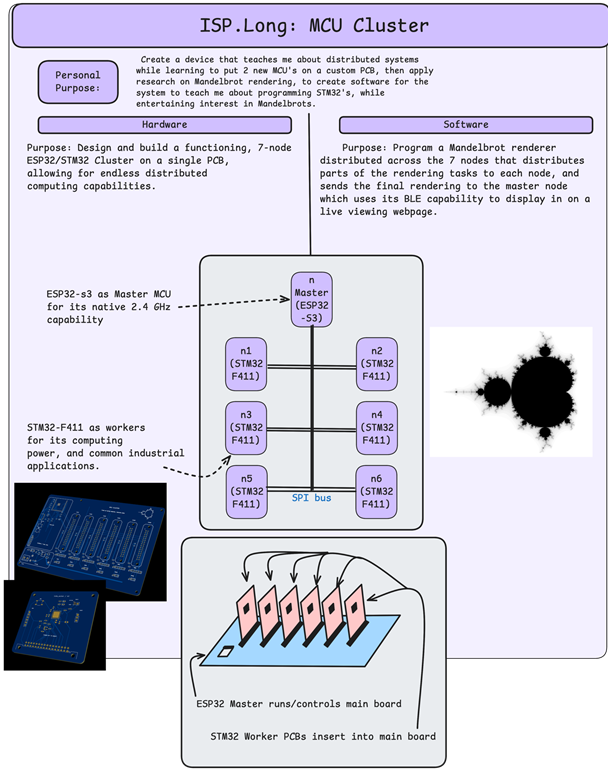
MCU Cluster
MCU ESP32-S3 , STM32 F411 DESIGN EasyEDA will be used for PCB design, and will be ordered through PCBWAY. COMMUNICATION The 6 STM32F411 communicate with the master ESP32-S3 via SPI. The ESP32-S3 communicates with a computer over BLE to show the finished rendering. MECHANICAL N/A |
??
DESCRIPTION MCU HARDWARE SOFTWARE DESIGN COMMUNICATION MECHANICAL |
Mitchell, G. |
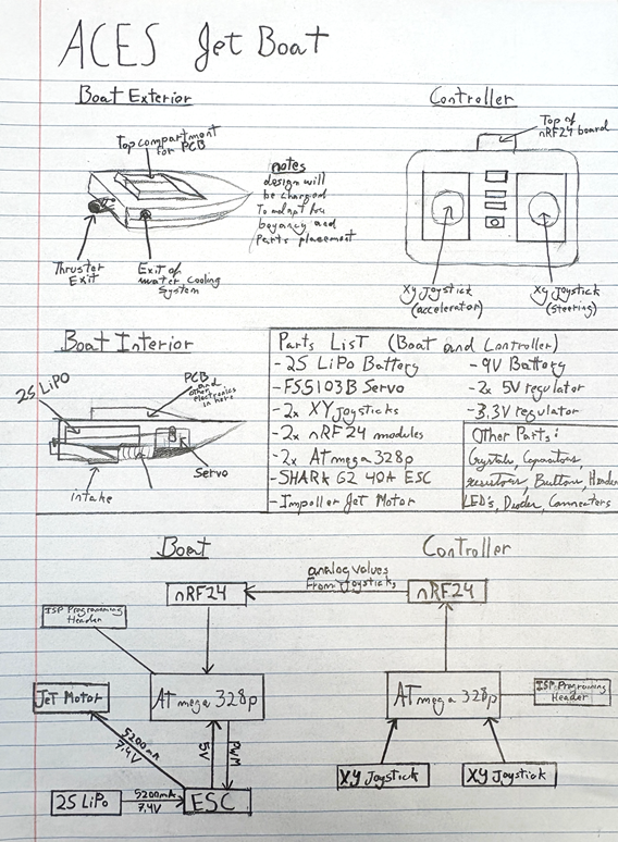
ACES RC Jet Boat
MCU 328p DESIGN EasyEDA will be used to design and order PCBS for the controller and the system board on the boat. Fusion 360 will be used to design a case for the controller, and the actual boat. COMMUNICATION RF is used to communicate between the control and system board on the boat. (nRF24 Module) MECHANICAL A servo will be used to control the steering, and a Water Jet Pump with a ZTW 40A ESC for the thruster. |
??
DESCRIPTION MCU HARDWARE SOFTWARE DESIGN COMMUNICATION MECHANICAL |
Northup, L. |
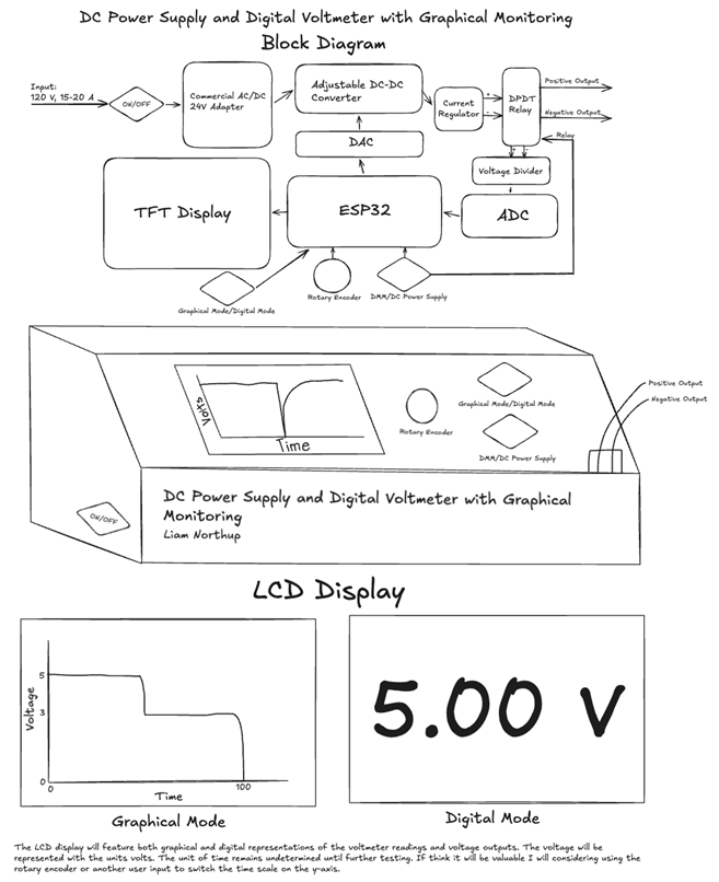
DC Power Supply and Digital Multimeter with Graphical Monitoring
MCU Nano ESP32 DESIGN The project with feature an enclosure designed using fusion. Internal PCBs will be used to for the internal circuitry. Externally the user will have access to a control panel PCB which will feature all user interfaces (rotary encode, switches, etc) as well as a power indicating LED. The case will display a colour TFT display to display voltage readings graphically and digitally. COMMUNICATION The microcontroller will communicate to the colour TFT using SPI communication and a dedicated ADC IC chip using I2C. MECHANICAL The project does not require any motors, servos, steppers, solenoids, or other electromechanical actuators. A rotary encoder and mechanical switches will be used for user input. |
??
DESCRIPTION MCU HARDWARE SOFTWARE DESIGN COMMUNICATION MECHANICAL |
Shaw, N. |
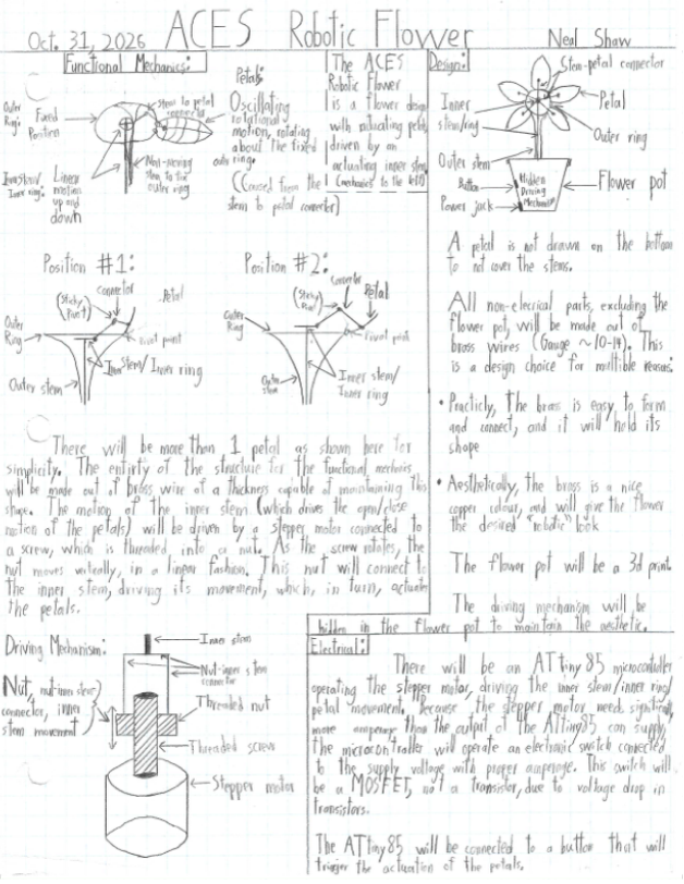
Robotic Flower
MCU ATtiny85 DESIGN Fusion will be used to create a flower pot. A perma-board will be used to create the circuit. The structure will be handmade out of brass rods of a thickness capable of maintaining its form. COMMUNICATION N/A MECHANICAL There is a stepper motor that rotates a screw, which has a nut threaded onto it. As the screw rotates, the nut will move up and down because the screw is in a fixed vertical position. The nut connects to a brass rod, which acts as a conductor for the linear actuation. This rod connects to a small ring, with brass connectors to each of the petals. As the ring moves up and down, the petals are let down and pulled up, hinging around a fixed outer ring. |
??
DESCRIPTION MCU HARDWARE SOFTWARE DESIGN COMMUNICATION MECHANICAL |