For the bulk of your formal education you have been, and will continue to be, required to consume curriculum chosen for you by someone else. Hopefully you will put this knowledge and skill to good use in your future.
However, jumping through someone else's hoops no longer secures future success. For that, you must put yourself in the driver's seat while in secondary school to both cultivate and demonstrate your own unique initiative, motivation, and passion. RSGC ACES program is explicitly built and tailored for you to foster these greater goals. Yes, there is much to learn but there are so many great projects to be undertaken and noble problems to be identified and solved that offer stimulating contexts within which to develop and refine your interests it will quickly seem more than worth the risk, effort, and cost.
The 7 Ps of a Successful ISP...
Preparation > Proposal > Prototyping > Preview > Production > Presentation > Publication
| Proposals |
ISP.Long Proposal
|
ISP.Medium Proposal |
Andrew, N.
|
ACES Battery Station
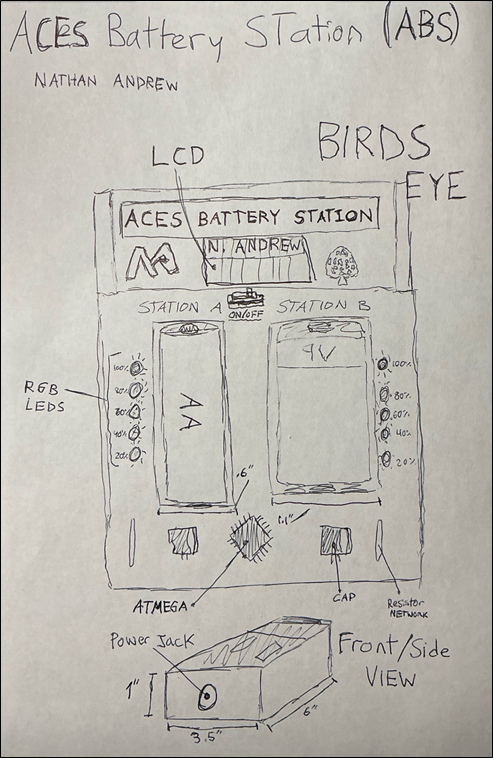
DESCRIPTION A dual bay smart charging and testing station designed for both AA and 9 V batteries. The station features a 16×2 LCD display that shows real-time voltage readings, charge levels, and battery status. Two vertical LED bars visually represent each battery’s health, ranging from red (low) to green (fully charged). Both bays charge safely using dedicated smart charger modules, while an ATmega328P microcontroller continuously monitors battery voltage, charging progress, and the overall system. Everything is housed in a custom 3D printed case with a clean layout.
MCU 328p
DESIGN Front panel and enclosure designed in Fusion 360 and 3D-printed.
Parts mapped out in EasyEDA for a custom PCB
Mounting holes and air vents made in Fusion 360 for clean assembly.
COMMUNICATION I2C for the LCD Display
Digital I/O for LED bars.
Analog inputs for voltage Serial Connection for debugging
MECHANICAL N/A
|
ACES Smart Drone
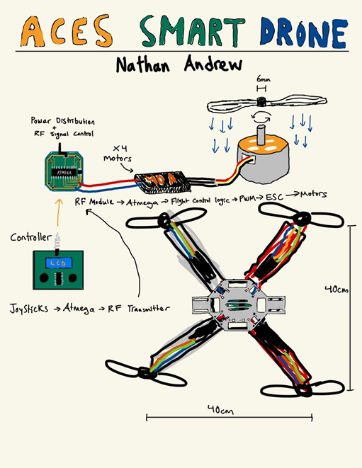
DESCRIPTION This project involves designing and building the ACES first fully working drone. A sturdy quadcopter frame, brushless motors, and ESCs are used for reliability, while a custom-designed PCB handles power regulation and clean signal routing between the flight controller, RF receiver, and motors. The main focus of the project is hardware integration, custom PCB design, and achieving stable, manual remote-controlled flight rather than advanced automation.
MCU 328p
HARDWARE ESCs
SOFTWARE Arduino C
DESIGN Fusion 360, JLCPCB, INAV(Stabilizer Calculator)
COMMUNICATION Serial, I2C, SPI, RF
MECHANICAL Brushless DC Motors
|
Darou-Santos, J.
|
TILIXI
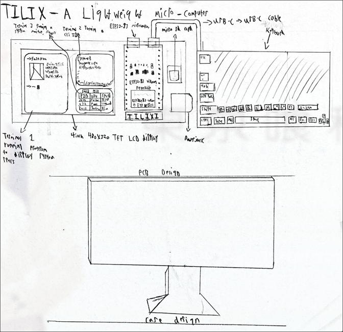
DESCRIPTION A microcomputer built around the ESP32-S3 running a custom lightweight Unix-inspired OS. The hardware consists of a TFT display, external keyboard and an SD card. The OS itself will include a GUI tiling manager (meaning the project wont all be TTY), simple filesystem, and the ability to execute CLI commands such as change directory, make directory, concatenate, grep, etc. The system is designed as a self-contained, low-resource “desktop” within the constraints of a microcontroller.
MCU ESP32-S3
DESIGN Fusion 360 for the case design, EasyEDA for PCB design and JLCPCB to manufacture the PCB.
COMMUNICATION SPI for TFT display and external flash/SD cards. Serial for programming/debugging via USB
MECHANICAL N/A
|
Eternal Life
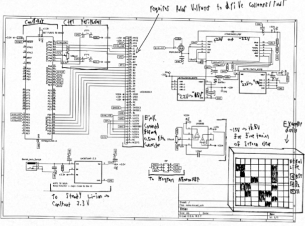
DESCRIPTION "Eternal Life" will serve to recreate Conway's Game of Life seamlessly on a raw E-Ink display. The board, which will communicate to the E-Ink, features an Atmega128p (lots of GPIO) to manually control column/rows through 22v/15v (positive and negative for polarity, which is needed for E-Ink), and send control signals through 3.3v for grayscale control and targeting of pixels. The 22v/15v comes from a DC/DC converter that will generate positive and negative 22v, which then goes to 22v-to-15v convertors (one for positive and one for negative). Additionally, a range between +15v/-15v controlled through a potentiometer goes to VCOM in order to fine-tune ghosting (a concept in E-Ink reverse engineering where pixels do not disappear fully), and the voltage needed on this pin varies screen to screen.
To achieve a functional product, the project has to accomplish four goals: make a PCB to get the proper voltages and connect the E-Ink to the Atmega128, bit bang the E-Ink with near cycle-perfect timing, write the game of life in AVR asm, and create a PCB (with proper routing for electrically sensitive components)/case design where it’s easy for the user to place/select pixels with a potentiometer and push button.
MCU ATmega128p
DESIGN Fusion360 for case
JLCPCB for manufacturing
SOFTWARE All AVR asm ideally; if not feasible then occasional Arduino C (only for E-Ink)
COMMUNICATION N/A
MECHANICAL N/A
|
Hooper, E.
|
Sun Aligned Power Station (SAPS Board)
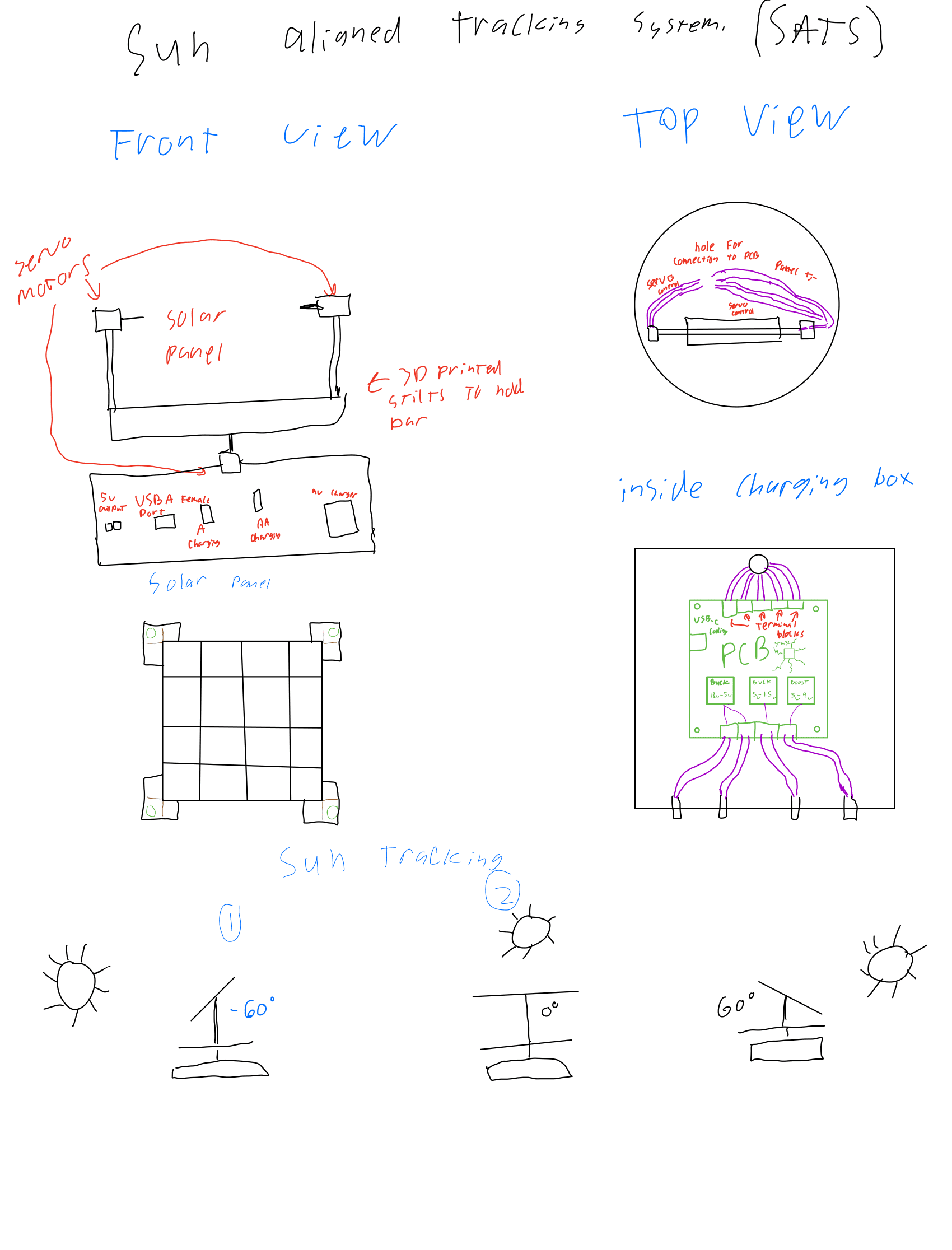
DESCRIPTION This project will involve creating a machine that can automatically follow the sun using LDRs and servo motors, the solar panel will follow the sun to maximize its output no matter the time of day and will let its power flow down through the bottom of the turntable that allows the whole thing to rotate using another servo. The output of the solar panel will be handled by the PCB inside of the box and its power will be saved to later be used to charge desired parts. The project will be power efficient and not use any batteries to run that it did not charge itself.
MCU STM32F411
DESIGN will be using Fusion360 to desing (sic) casing for the project to allow for clean operation.
will be using EasyEDA and JLCPCB to create the SAPS board to manage power.
COMMUNICATION Don’t think will be using any, potentially a 1306 OLED using I2C screen to show status of charging and batter remaining power.
MECHANICAL 3 Servos, 1 to rotate the machine on the y-axis and 2 to rotate the solar on the x-axis to follow the sun |
DDS Waveform Generator
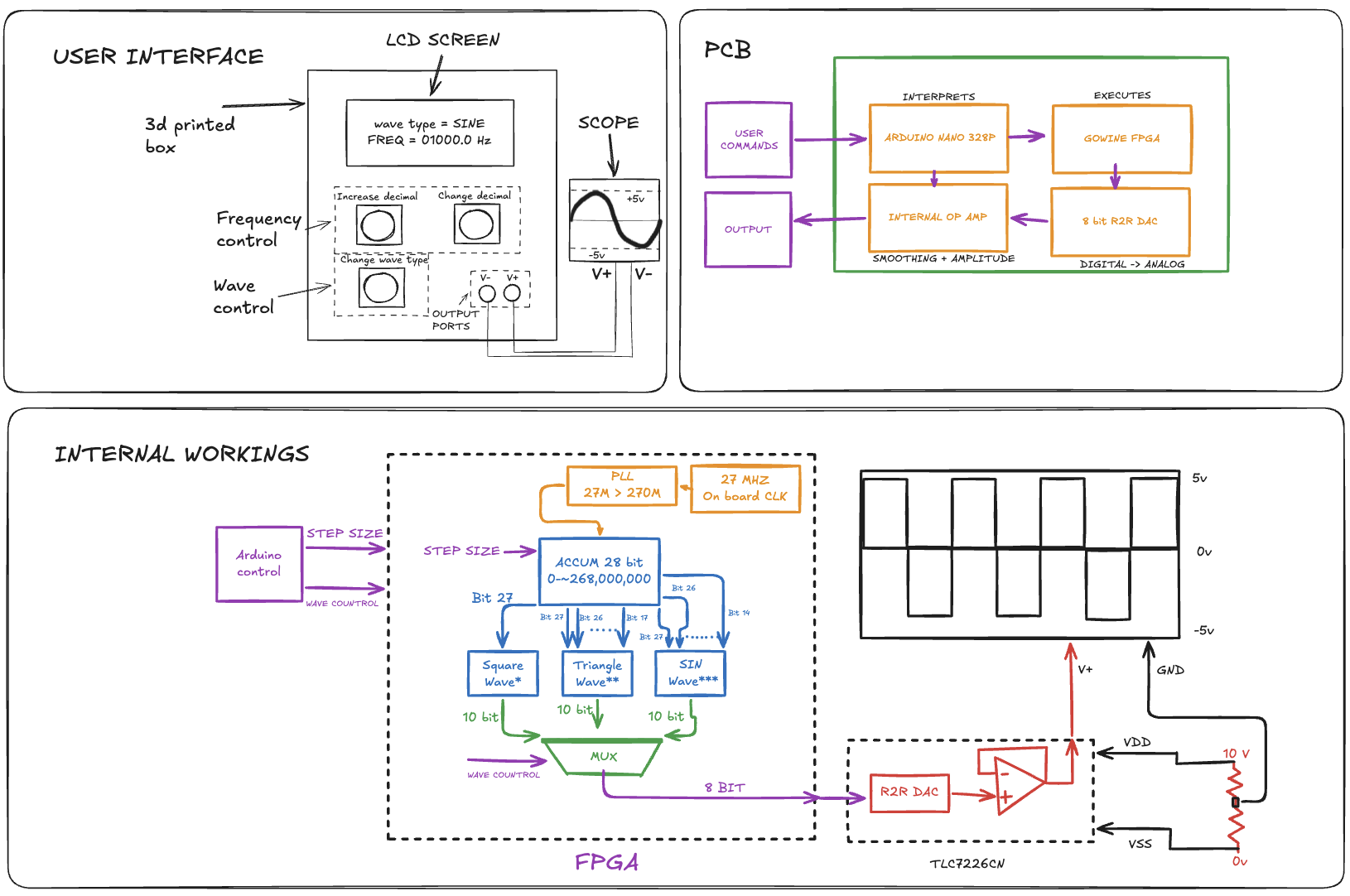
DESCRIPTION Will use a FPGA and Verilog to create two 28 bit Direct Digital Synthesis (DDS) counters that supplies a sin, square, and triangle wave ROM and will utilize a MUX to let the user select which wave output they want. The device will also use op amp gain mechanics to allow the user to select a certain amplitude for the wave. The project will also use a Arduino as a user interface to power a LCD and user controlled buttons and dials.
MCU 328p
HARDWARE Gowin FPGA
SOFTWARE VERILOG (Hardware Design Language) and LCD LIBRARY
DESIGN Will make a box with a PCB indie [sic] using Fusion360 and JLCPCB
COMMUNICATION Will use some sort of communication protocol to have the Arduino communicate with FPGA. CD: ???
MECHANICAL N/A
|
Lamarre, T.
|
Wire Cutter
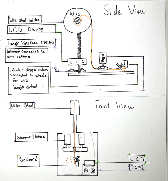
DESCRIPTION This wire cutter will use two stepper motors to roll out a precise distance of wire through an extruder. A solenoid motor will then cause a pair of wire cutters to close, cutting a precise and specific length of wire. The wire length will be adjustable through a button interface.
MCU 328p
DESIGN Fusion 360 will be used for a 3D printer style design, where the wire stool will rest on top, with the wire leading into an extruder. Only difference is the extruder will push the wire horizontally to the surface to set up a potential wire stripper. On that same horizontal place, the wire cutter system will be placed. The components for the display will be put together on a PCB.
COMMUNICATION Serial communication will be used for communication with the motors and buttons, and I2C will be used for communication with the LCD interface.
MECHANICAL Wheels will be attached to stepper motors to precisely roll out wire within the extruder, and a solenoid motor will be used to close the wire cutters.
|
Blender
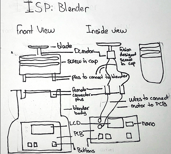
DESCRIPTION This ISP Medium project involves designing and building a small, Arduino-controlled blender. The system uses a DC motor connected to a metal blade to mechanically break down solid materials into a liquid or semi-liquid form. An Arduino Nano serves as the main controller, interfacing with push buttons for user input and an LCD display to provide operating information such as status or run time. The blender’s structure will be custom designed and 3D printed, built around a reusable plastic container that functions as the blending cup.
MCU 328p
HARDWARE Nano
SOFTWARE Arduino C
DESIGN Fusion 360 used for blender body JCLPCB used for circuitry
COMMUNICATION Serial Comm. and I2C for the LCD
MECHANICAL DC motor for the spinning blade
|
Lowry, T.
|
ACES Alarm Clock
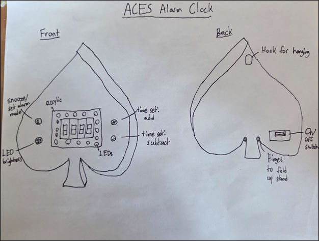
DESCRIPTION The ACES alarm clock would use a crystal to keep time and charlieplexed seven segment displays to show the time. The clock should be as space efficient as possible and able to be battery powered or adapter powered. The time setting and alarm setting will be done with two buttons, one to add and one to subtract, that will rapidly increase when held down. Additionally, there will be LEDs that gradually light up as the alarm time approaches to gradually wake the user up. There will be another button to set the different brightness levels of the LEDs. Finally, there will be a button that will enable the setting of the alarm and act as a snooze button.
MCU 328p
DESIGN Fusion360, EasyEDA, JLCPCB
COMMUNICATION ?
MECHANICAL ?
|
Scratch Tester
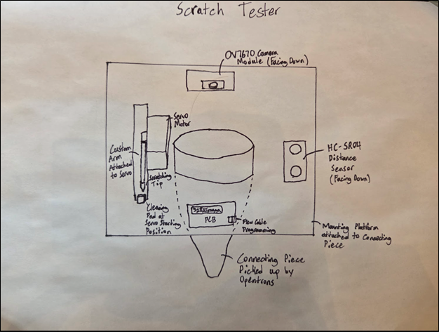
DESCRIPTION The scratch tester will attach to an Opentrons device that will control the x,y, and z positioning of the device. The scratch tester will know it is in position using a distance sensor to measure the tip’s distance from the sample. From there, the scratching tip, which is attached to a servo motor, will swing down, scratching the sample. The sample could be scratched using different forces if necessary. The tip will then go back to its starting position, where a cleaning pad will remove any residue to avoid cross-contamination. Finally, a camera module will take a photo of the resulting scratch to see if the adhesive has remained or rubbed off. The scratch tester will then move on to the next sample and continue until all samples are scratched.
HARDWARE 328p
SOFTWARE The code will test the distance (with the HC-SR04), swing the arm, either using half or full stepping depending on the desired force, to the desired sample to scratch it and then move back. Finally, a OV7670 library will be used for the camera to take a photo of the scratch.
DESIGN The project will use Fusion 360 to make the mounting platform, pipette connecting piece, and servo arm. JLCPCB will be used for the PCB design.
COMMUNICATION The OV7670 camera module uses I2C (I2S?) communication.
MECHANICAL The scratch tester makes use of a servo motor to control the scratching tip.
|
Malcolm, E.
|
Foamboard RC Plane
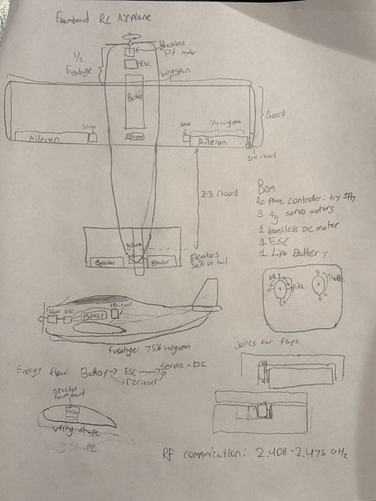
DESCRIPTION This project involves designing and building a small RC airplane from foamboard. The plane will be controlled using a FlySky FS-i6X 10CH 2.4 GHz AFHDS 2A transmitter and FS-iA10B receiver, a reliable standard RC system. The receiver will directly drive servos for control surfaces (elevator, aileron) and an ESC for the brushless motor. 3D-printed mounts will secure the motor, servos, and control horns, keeping the plane lightweight and stable.
MCU None provided
DESIGN Airframe designed in Fusion 360, built from foamboard
3D-printed parts: motor mount, servo brackets, control horns
PCB for plane receiver to neatly connect nRF24L01, BEC, and servos.
COMMUNICATION FlySky FS-i6X 10CH 2.4 GHz AFHDS2A RC Transmitter → FS-iA10B Receiver PWM outputs from receiver to servos and ESC.
MECHANICAL Brushless DC motor with propeller
Electronic Speed Controller for motor
3 9g servos: elevator and aileron control
Foamboard airframe, reinforced with tape or lightweight spars 3D-printed parts for mounting and control linkage |
Consistent Sample Imaging Box (CSIB)
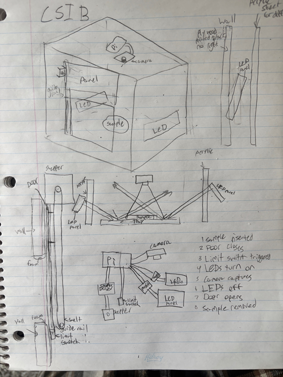
DESCRIPTION This project is an imaging box designed to capture consistent, top-down images of reflective samples between 3 and 5 inches in diameter. The main priority is consistency in lighting, framing, and exposure to support accurate AI analysis. The box will fully block ambient light to prevent variation between images. Even, angled LED lighting will be used to reduce glare and prevent the camera lens from appearing in reflections. The lighting will remain fixed to ensure the same conditions for every capture. The camera will be securely mounted in a level, top-down position. Focus, exposure, and white balance will be manually set and locked. The sample will sit on a neutral, non-reflective platform to maintain a consistent background. Samples will be inserted from the side by a robotic arm. Once the enclosure is sealed, the system will activate the lighting and capture the image under identical conditions each time. The design focuses on stability and repeatability to produce standardized images for AI training and analysis.
MCU Dual-core ARM Cortex-M0+
HARDWARE Raspberry Pi
SOFTWARE Python
DESIGN Design will be made in fusion, some 3D printed parts, black paint, arcylic sheets.
COMMUNICATION CSI/Ribbon Cable for the Camera
MECHANICAL Stepper motor with a limit switch to move door up/down along guide rails. |
Mulcahy, K.
|
ACES Remote Controlled Boat (ACESRCB)
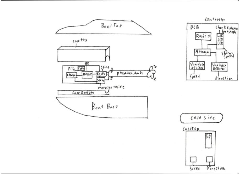
DESCRIPTION This Project will incorporate design software and hardware to create a radio-controlled boat. This boat will be powered by a DC motor regulated by a MOSFET. The project is designed to challenge my design, hardware, and software skills. The main challenge will be design and being able to keep water outside of my electrical components. The controller will be connected via radio to the boat and use variable resistors to control speed and direction.
MCU 328p
DESIGN I will use Fusion 360 to create my encasement and design my boat. I will also use it to create a user-friendly controller. EasyEDA and JLCPCB will be used to create my controller and motor control PCB they will use surface mount components and be small and well thought out. The boat will have a front water tight are for the electronics and a shaft from the motor to the back with the propeller.
COMMUNICATION I will use radio communication to control the boat from a controller and this will all be done on an atmega328P. This is to allow long distance complete control over the boat.
MECHANICAL This project will utilize a DC motor as the driving force of the boat and a servo to control the direction of the propeller. These will be controlled by an atmega328P and powered by a 9V battery. |
ACES Gear Box
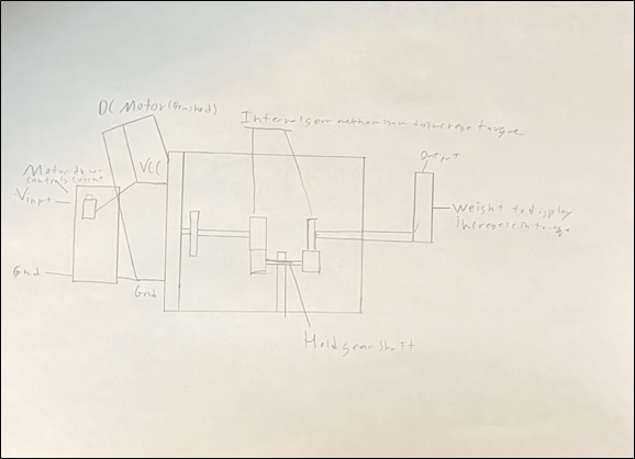
DESCRIPTION This project aims to challenge my mechanical and design skills. It will be able to increase the torque of a DC Brushed Motor and through the use of gear ratios increase the torque on the final output. This project will help me improve my skills in mechanical and challenge my abilities improving my knowledge of gears and motors.
MCU
HARDWARE
SOFTWARE
DESIGN I will design a gear box on fusion and a potential PCB
COMMUNICATION
MECHANICAL There will be a DC Brushed Motor and Gears.
|
Odoemelam, D.
|
The Custom Mechanical Keyboard
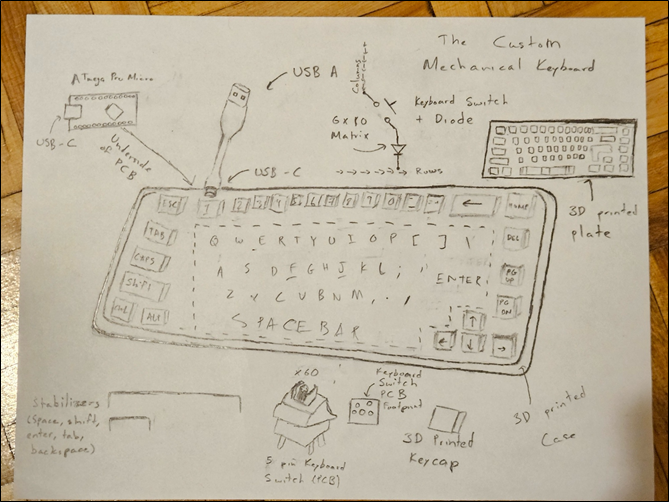
DESCRIPTION The Custom Mechanical Keyboard is a fully functional USB keyboard designed and programmed from scratch, focusing on the design and software components of engineering. It is a 65-form factor keyboard including a full alphanumeric layout, modifier keys (Shift, Alt, Ctrl, and Caps Lock), arrow keys and other function keys (Escape, Enter, Tab, and Backspace). The keyboard will be powered through a USB connection to a computer, functioning as a Human Interface Device (HID). The keyboard will use 5-pin PCB-mount mechanical switches arranged in a matrix with diodes (the diodes are to prevent ghosting and ensure overall accuracy). There will also be stabilizers for larger keys (space bar, enter, etc.). I will be using the ATmega Pro Micro (ATmega32U4) as the MCU to code my own matrix and keymap.
MCU ATmega Pro Micro/32U4
DESIGN KiCad/EasyEDA – Design the keyboard’s PCB
Fusion 360 – Design the keyboard’s keycaps, plate and case
KeyboardLayoutEditor – Initial Design for my Keyboard + PCB Layout
COMMUNICATION USB (Human Interface Device (HID))
MECHANICAL The buttons themselves
|
Analog HID Hall Effect Keypad (Sayo Device)
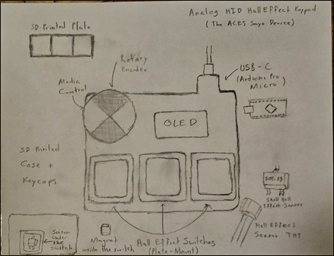
DESCRIPTION The Hall Effect Keypad is a three-key analog input device featuring a rotary encoder and an OLED display. While smaller in scale than my previous 65% keyboard, this project represents a significant step up by shifting focus from simple digital switching to high-speed analog signal processing and interrupt-driven firmware. This device will use Hall Effect (magnetic) sensors instead of mechanical switches. By measuring the magnetic field strength as a key is pressed, the sensors provide continuous analog data regarding the key’s exact displacement. This data is processed by Arduino Pro Micro’s (ATmega32u4) internal ADC, allowing me to implement a rapid trigger algorithm. This firmware logic enables dynamic actuation points and reset thresholds that respond instantly to the velocity of a keypress. The firmware utilizes Hardware Timer Interrupts. This allows the MCU to prioritize sampling the analog sensors at a consistent 1ms interval, ensuring a stable 1000Hz polling rate regardless of the OLED’s processing load. I will be 3D printing a case, designing custom keycaps in Fusion 360, and manufacturing a custom PCB.
MCU ATmega32u4
HARDWARE Arduino C (Register Level)
SOFTWARE For the software, I will write register-level code to optimize the ADC conversion speed.
While I will use the Wire.h library for basic I2C communication and the HID-Project
library for the Arduino USB stack for connectivity, the performance logic will be
written from scratch. This includes Direct Register Access for high-speed ADC sampling,
a custom state machine for the 'Rapid Trigger' magnetic logic, and a manually configured HID Descriptor to force a 1 ms polling rate.
DESIGN Fusion 360/KiCad/JLCPCB
COMMUNICATION USB HID, I2C, Quadrature Encoding (for the rotary encoder)
MECHANICAL Rotary Encoder
|
Shen, A.
|
Auto Card Dealer
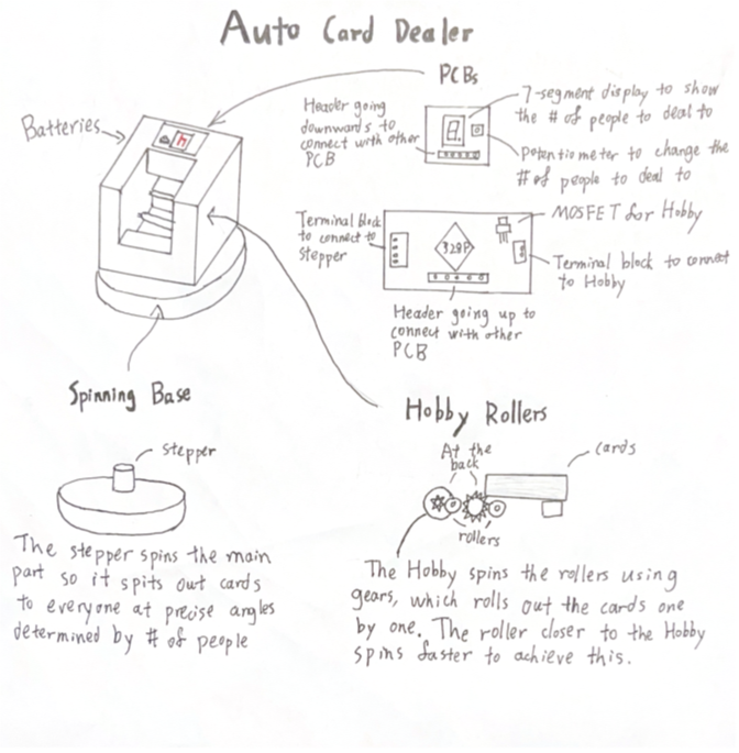
DESCRIPTION The Auto Card Dealer deals out poker cards for games like poker, president, and much more. It uses a stepper motor to rotate the output a specific degree every time for a number of people, which is shown on 7-segment displays, and can be changed using a potentiometer. After each turn, two rollers connected to a hobby motor deals out one card. A battery is used since the rotating will cause a power cord to get tangled.
MCU 328p
DESIGN The PCB will be designed in EasyEDA and made by JLCPCB. Most of the parts, if not all, will be surface mount. The case will be made in Fusion360.
COMMUNICATION N/A
MECHANICAL For the stepper motor, a NEMA 23 motor will be used with a DM542T driver since the motor needs to be strong to turn the output of the cards. A 24 V battery pack will be used with it. The hobby motor will just be the one in the kit. |
Desktop Study ACESistant
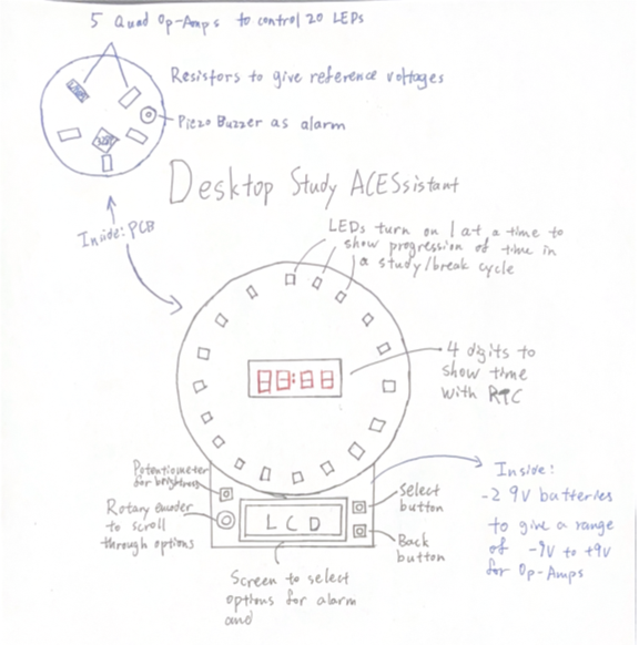
DESCRIPTION This is a study assistant that can be placed on a desk. It helps the user keep track of the time when studying by having a ring of LEDs that turn on 1 by 1 to display the progress of time for studying and break cycles. These are set by the user on an LCD screen using a rotary encoder and some buttons. There are also 4 digits in the center of the LEDs that can either be the countdown timer or the actual time, gotten through an RTC. This allows the device to be multi-purpose, serving as an alarm clock with the addition of a buzzer. The ring of LEDs are controlled by 1 singular pin from the microcontroller, which is the surface-mount ATmega328P-AU, giving a voltage value, and each LED has an Op-Amp with a different reference voltage to turn them on one at a time by slowly changing the voltage from the MC. The reference voltages will be given by resistors, and since head room is required for Op-Amps, two 9 V batteries are used to give a -9 V to +9 V range.
MCU 328p
HARDWARE
SOFTWARE Arduino C
DESIGN The case is designed in Fusion360, and the PCB is created through EasyEDA and made by JLCPCB
COMMUNICATION I2C communication is used by the LCD and RTC
MECHANICAL Piezo Buzzer
|
Willis, N.
|
The Pocket Arcade Cartridge Engine (ACE)
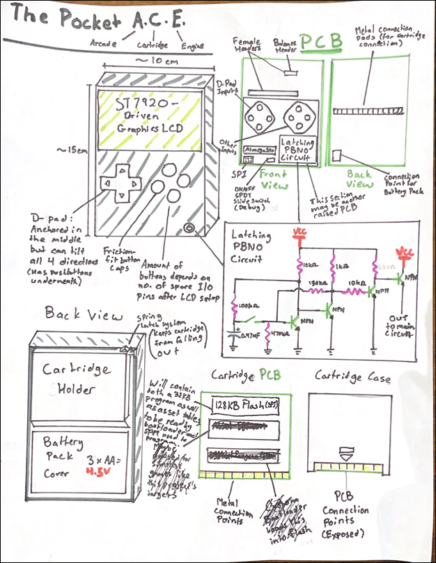
DESCRIPTION The Pocket ACE will consist of a main PCB (might be two, to account for height differences in parts), which will house the inputs, GLCD display, and MCU, as well as several cartridge PCBs, which will have pads along the edge similar to a modern RAM chip or SD card. The cartridges will each house an SPI NOR flash IC. The main board will have an onboard edge pin connector which the cartridges will be swappable in and out of. On startup, the MCU’s custom-written bootloader will check for an inserted cartridge, and if there is one, read the first 32 KB of its flash memory where the program will be stored, and execute self-program memory (SPM) to program its own flash page by page. The program will then be run. The rest of the cartridge memory will be used to store asset tables if necessary (sprite tables, sounds, etc.) although the simple games which this project targets may not utilize this section of memory.
MCU 328p
DESIGN This project will include a main PCB (maybe two to account for height differences in parts) and several identical cartridge PCBs, which will connect to the main PCB through an edge pin connector and edge pins. All 3D modelling (for both main device and cartridges) will be done in fusion, and PCB design on EasyEDA Pro. PCBs will be ordered through JLCPCB.
COMMUNICATION The cartridges, which will house SPI NOR flash ICs, will communicate with the MCU through SPI communication.
MECHANICAL N/A
|
8-Bit Princeton CPU Addressing and Control Systems
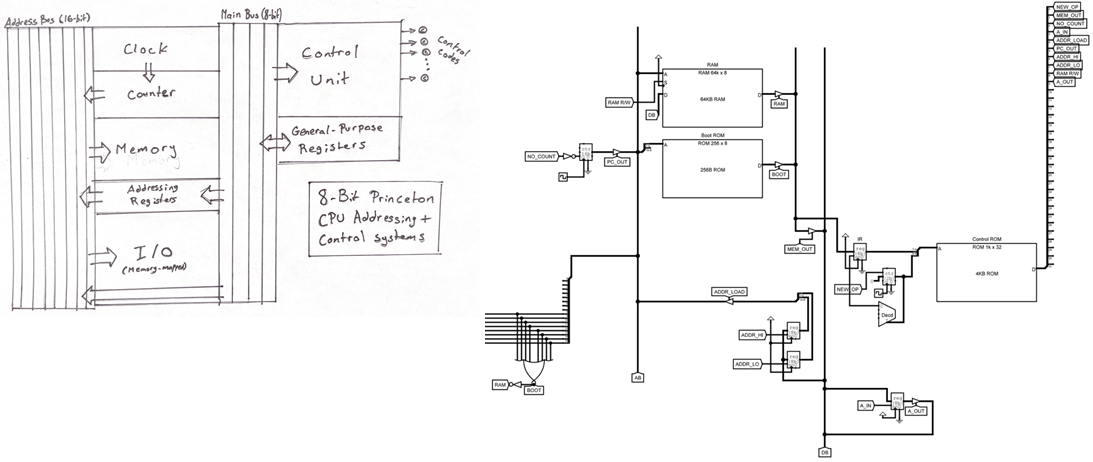
DESCRIPTION This project will be part of an 8-bit Princeton CPU with 16-bit addressing. As it would be unrealistic to build this entire CPU, it will instead only feature an addressing system with memory-mapped I/O, an instruction register and control EEPROM with a setup for multi-word instructions, a couple general-purpose registers for moving data around, and address registers for addressing into memory. It will not feature an ALU or a stack, which means it will not be a complete CPU. This project will be complete if I can attach an EEPROM holding a program to an I/O port, and run a bootloader program stored on another permanently installed EEPROM that will write that program into RAM and run it. This project has already been simulated in a prototype form in Logisim Evolution.
MCU No MCU will be used, this project will be built with the same level of hardware as CHUMP.
SOFTWARE No high-level software will be used, except to program EEPROMs.
DESIGN This project will be designed only on breadboards, as attempting to use perfboard or PCB to make the project permanent does not fit within the time frame/scope of the project. This is also a project that will require a lot of debugging and moving wires around, which is much easier to do if it is kept on breadboards. Most of the design field of this project will come from the CPU design itself, which is done entirely by me.
COMMUNICATION Almost entirely parallel communication will be used. For example, the EEPROMs and RAM will be parallel devices, not serial.
MECHANICAL N/A
|
Xie, W.
|
ACES Video Game Controller
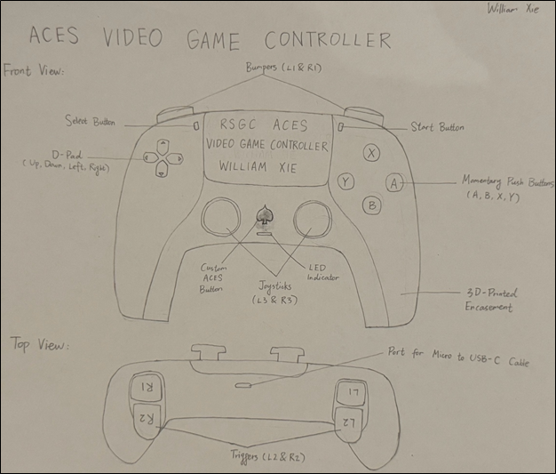
DESCRIPTION This project is a custom wired video game controller that can be used to play video games on MacBooks. The controller will be connected to the MacBook via a Micro to USB-C cable, which allows the controller to send data to the MacBook and draw power from the MacBook at the same time. When the controller and the MacBook are connected, an LED indicator will light up, indicating that the controller is powered. Momentary push buttons and joysticks will be used as the inputs of the controller, and the MCU for this project, which is a surface mount ATmega32U4, will read the states of all inputs continuously and create USB HID (Human Interface Device) reports based on these states. The macOS will receive these reports from the ATmega32U4 every few milliseconds and interpret them as gamepad input events, which are then sent to the game and the game will react based on its rules. Each button will have its own custom 3D-printed button cap to show its identity (A, B, X, Y, L1, R1, etc.).
MCU ATmega32u4
DESIGN There will be 2 PCBs for this project, and both of them will be designed in EasyEDA. The main PCB will be in the shape of the controller and all parts other than the joysticks and buttons will be surface mount. The second PCB will be perpendicular to the main PCB to accommodate the bumpers and triggers (L1, R1, L2, and R2). The housing of the controller and the custom button caps will be designed in Fusion 360 and 3D printed.
COMMUNICATION USB HID.
MECHANICAL Momentary push buttons and joysticks. |
Mega-Mini
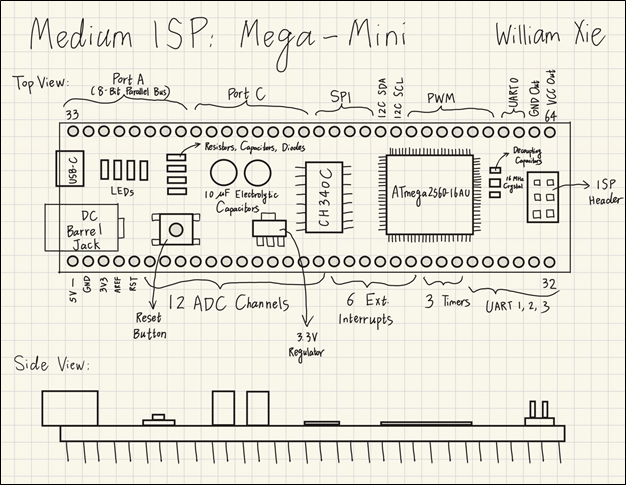
DESCRIPTION This project is a breadboard-compatible development board that features an ATmega2560. Since the 2560 has 100 pins, the development board will take up almost the entire breadboard if all pins are broken out. Therefore, the Mega-Mini only breaks out the 64 most important pins on the 2560, and they are divided equally into two rows, so there will be 32 pins on each side of the board, leaving half of the breadboard for prototyping. The Mega-Mini will be wider than typical breadboard-compatible development boards (Nano, Pro Micro, etc.), as the 2560 has a much larger size than other MCUs, so there will be only one row left on each side of the breadboard for wirings when the Mega-Mini is attached to the breadboard. In addition to the 2560, there will be a CH340C serial chip, a 3.3 V regulator, a reset button, a USB-C connector, a 2.1 mm DC barrel jack, an ISP header, and some resistors, capacitors, and diodes on the Mega-Mini. All components except for the barrel jack and the ISP header will be SMD. The final board will keep almost all of the most important features of the 2560, including 4 hardware UARTs, 6 external interrupts, 3 timer inputs, 6 high-resolution 16-bit PWM outputs, 12 ADC channels, an 8-bit parallel bus, SPI and I2C communication protocols, and a total of 58 GPIO pins.
HARDWARE 2560
SOFTWARE Arduino C (high-level) and Assembly will be used to test the functionality of the final board.
DESIGN The Mega-Mini PCB will adopt a 4-layer design. In addition to the standard top and bottom layers for signal traces, there will be a solid ground plane (layer 2) that acts as the heat sink for the 2560 and a power plane (layer 3) that will be split so one area is 5 V and a smaller section is 3.3 V. No 3D printing is involved in this project.
COMMUNICATION The final board will be able to communicate with other devices via UART, SPI, I2C, and USB.
MECHANICAL N/A
|

 To my mind, the characteristics of a great project include such aspects as imagination, creativity, a degree of risk and, sometimes, even simplicity, to name a few. Check out the flashlight circuit 'board' this guy made out of little more that a piece of paper and a pencil? Simple, but inspiring.
Consider a problem that needs a solution. Boyan Slat did at age 17 when he was in high school; four years later he is
To my mind, the characteristics of a great project include such aspects as imagination, creativity, a degree of risk and, sometimes, even simplicity, to name a few. Check out the flashlight circuit 'board' this guy made out of little more that a piece of paper and a pencil? Simple, but inspiring.
Consider a problem that needs a solution. Boyan Slat did at age 17 when he was in high school; four years later he is 