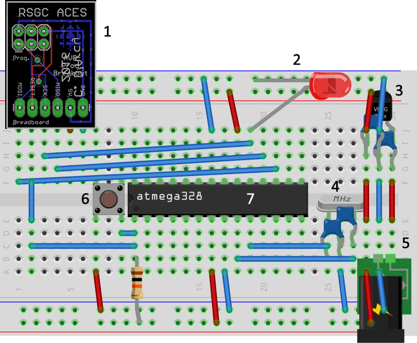
Here's a summary of how to get started with a standalone Arduino or, more accurately, a standalone ATmega328 (Click to enlarge either image). Clockwise from the top left,
- (Optional) Using the RSGC ACES ISP Breakout board, your can reflash the IC while it remains in place.
- The LED is attached to PORTB, Pin 5 aka digital pin 13. No resistor is necessary as there is an internal 20K en each of the output pins.
- (Optional) The operating voltage range of the ATmega328P is 1.8-5.5V. To permit the use of 6V-12V ACDC Adapter, one should use either a 78L05 (max 100mA) or 7805 (max 1A) voltage regulator. Shoulder caps (~33uF) are optional over these short distances but are recommended for filtering noise.
- The typical operating frequency of the ATmega328P is 16MHz. An external crystal, again with shoulder caps provides the most accurate clock signal. A 16MHz three-pin resonator is a convenient alternative as it has builtin capacitors.
- A DC Jack in this position provides convenient access for external power.
- A reset switch, attached to a 10k pullup resistor, is used to restart the sketch.
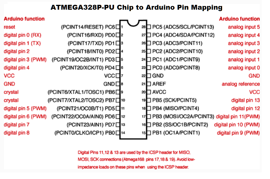
- The 28-pin ATmega328P microcontroller IC.