| RSGC ACES: ICS3U-E Standalone ATmega328P |
First of all, this page is not attempting a breadboard 'Arduino' build. Those geniuses at MIT 15 years ago packed a myriad of brilliant functionality onto that little blue PCB beyond an MCU, crystal, caps, and resistors. Rather, in fairness, I think a breadboard 'ATmega328P' is the fairer representation of the direction this guide steers you in.
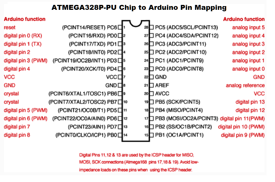
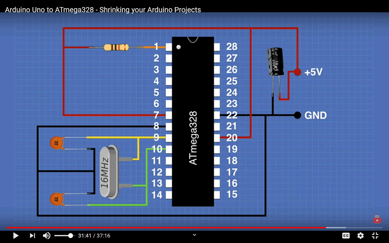
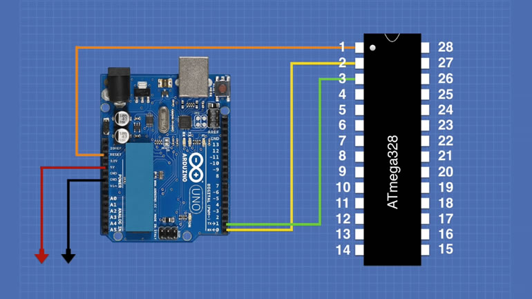
Examine the two images below, carefully. The one on the left details how the ATmega328P IC pins (black) are mapped to the female headers (red) on Arduino UNO. The image on the right depicts the connections a (breadboarded) ATmega328P should have, to be minimally functional.
|
|
Image Reference: https://youtu.be/Sww1mek5rHU?t=1901
Now, of course 'minimally functional' is not what we're after. We need to demonstrate that our MCU-based prototype can, eventually, do something reasonably interesting and be reflective of our expanding skill set. I used the word 'eventually' because the journey to the ultimate final device will be a gradual process, littered with numerous iterations, unsuccessful attempts, misdirections, and trials. For this reason, the ability to reprogram and debug the ATmega328P in place (without removing it from the breadboard) is essential and a fair expectation of what should follow in the guide below.
Requirements
Here are the primary constraints for this build,
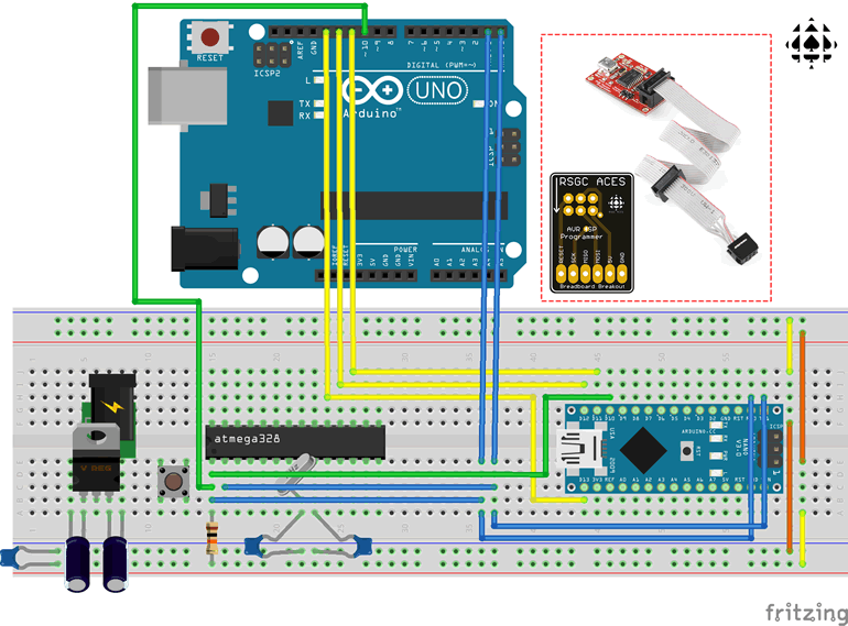
Taking these three requirements into consideration leaves us with the (general) hardware configuration and options below. The major 'supporting cast' members (of which you currently have all of) includes the 5V regulation in the bottom left corner and THREE(!) device options to assist with programming your ATmega328P. Purposely absent from the diagram are the numerous connections and jumper wires, not only to avoid this becoming a paint-by-numbers exercise, but to improve the chances of a functional perma-proto version in Project 2.4.2, as a result of your investment in the knowledge and skill to achieve a working breadboard prototype. Further details and explanation follow after the graphic.
Serial Peripheral Interface (SPI) and Serial USART (Tx/Rx)
The ATmega328P MCU includes onboard hardware support for the Serial Peripheral Interface, or SPI (Chapter 19) and the Universal Synchronous and Asynchronous serial Receiver and Transmitter, or USART (Chapter 20). Each can be exploited to meet the some or all requirements of this task.
SPI Programming of a Standalone ATmega328P
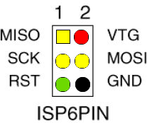 In the Fritzing image above the three yellow wires (MOSI, MISO, SCK), together with the green wire (RESET) and the two supply lines not shown (5V: RED, GND: BLACK) form a 6-wire set of control lines that form the SPI communication protocol used to communicate with your in-place ATmega328P.
You have three hardware options in your kit for uploading code from your Arduino IDE to your breadboard MCU using SPI, each having their own pros and cons. None of them support use of the Serial Monitor/Plotter for debugging and display.
| Option | PROs | CONs |
|---|---|---|
| UNO | Good practice using Arduino as ISP |
Tricky, multistage programming sequence Messy, unstable wiring Not practical for Project 2.4.2 |
| Nano | Smaller form factor than UNO Stable, clean wiring between two breadboard devices |
Tricky, multistage programming sequence Not practical for Project 2.5 No Support for Serial IO (Monitor/Plotter) |
| SAPP + AVRISP BoB |
Neither the UNO or Nano required |
Expense No support for Serial IO (Monitor/Plotter) |
USART (Serial Rx/Tx) Programming of Standalone ATmega328P
 Every program you've ever flashed onto the UNO's ATmega328P has been achieved through the support of its USART or Serial Rx/Tx pins 2 and 3 (digital pins 0 and 1). It has fallen to the onboard AVR ATmega16u2 MCU, positioned strategically in close proximity to the USB cable input plug, to accept your computer's USB signal protocols and convert them to Serial Rx/Tx signals. In similar fashion, when your code sends serial output signals, intended for your Arduino IDE's Serial Monitor/Plotter, it must first pass through the Rx/Tx pin combination, to the ATmega16u2 for conversion to USB and, ultimately, your computer's display.
It may now seem obvious to some readers how this technique can be applied to programming a breadboard ATmega328P. If we simply remove the ATmega328P from its socket on the UNO, wire the 5 connections (Rx/Tx/Reset/5V/Gnd) as shown in the diagram to the right, uploading your sketches from the Arduino IDE will reach its breadboard target in exactly the same fashion! Return to this terrific video to see a clear presentation of how this accomplished, https://youtu.be/Sww1mek5rHU?t=1565
Serial Monitor/Plotter: Debugging and Display (only partially confirmed)
Using only the tools you have in your kit, the only way in which your breadboard ATmega328P can make use of your Arduino IDE's Serial Monitor and Plotter for debugging and display is to relay the data through the UNO's USART's Serial Rx/Tx header pins with the UNO's ATmega328P removed.